
Related Manuals for Control Techniques Epsilon EP-P


Summary of Contents for Control Techniques Epsilon EP-P
- Page 1 Reference Manual Epsilon EP-P Servo Drive ® "MOTION MADE EASY" Part Number: 400518-04 Revision: A4 Date: December 29, 2017...
- Page 3 Information furnished by Control Techniques Americas is believed to be accurate and reliable. However, no responsibility is assumed by Control Techniques Americas. Control Techniques Americas reserves the right to change the design or operation of the equipment described herein and any associated motion products without notice. Control Techniques Americas also assumes no responsibility for any errors that may appear in this document.
- Page 4 Information in this document is subject to change without notice. No part of this document may be reproduced or transmitted in any form or by any means, electronic or mechanical, for any purpose, without the express written permission of Control Techniques Americas.
-
Page 5: Customer Support
That is why we offer you so many ways to get the support you need. Whether it’s by phone, fax or email found on our website, you can access Control Techniques support information 24 hours a day, seven days a week. - Page 6 (Alt,F) Reference Materials The following related reference and installation manuals may be useful with your particular system. • Epsilon EP Installation Manual (P/N 400518-01) • Epsilon EP Connectivity Manual (P/N 400518-05) Epsilon EP-P Drive Reference Manual www.controltechniques.com Revision: A4...
-
Page 7: Safety Information
NOTE For the purpose of this manual and product, “Note” indicates essential information about the product or the respective part of the manual Throughout this manual, the word "drive" refers to an Epsilon EP-P drive. v www.controltechniques.com Reference Manual Revision A4... - Page 8 AC supply voltage. External control circuits identified as PELV circuits do not need this isolation when they are completely within a zone of equipotential bonding, generally within a single enclosure or group of enclosures bonded together. Epsilon EP-P Drive Reference Manual www.controltechniques.com Revision: A4...
-
Page 9: Table Of Contents
Graph View ................25 vii Epsilon EP-P Drive Reference Manual Revision A4... - Page 10 Online Tab ................48 viii Epsilon EP-P Drive Reference Manual www.controltechniques.com...
- Page 11 Source ................87 ix Epsilon EP-P Drive Reference Manual Revision A4...
- Page 12 Example Programs ............... 139 Epsilon EP-P Drive Reference Manual...
- Page 13 ETH-PATCH................223 xi Epsilon EP-P Drive Reference Manual Revision A4...
- Page 14 Glossary Index Epsilon EP-P Drive Reference Manual www.controltechniques.com Revision: A4...
-
Page 15: Introduction
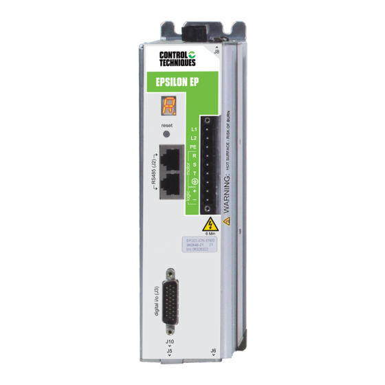
(EP-IDN or EP-PDN only) Connector (J4) (EP-Pxx only) Digital I/O Connctor (J3) Sync Input Connector (J10) Analog/Sync Output Encoder Feedback Connector (J6) Connector (J5) Figure 1: Epsilon EP-PDN (EP202-206) Drive Feature Location 1 Epsilon EP-P Drive Reference Manual Revision A4... - Page 16 Revision and Serial Number Label (EP-PDN only) Sync Input Connector (J10) Digital I/O Connector (J3) Profibus Connector (J13) (EP-PPB only) Analog/Sync Output Encoder Feedback Connector (J6) Connector (J5) Figure 3: Epsilon EP-216 Drive Feature Location Epsilon EP-P Drive Reference Manual www.controltechniques.com Revision: A4...
-
Page 17: Operational Overview
Operational Overview This section provides a complete functional description of the Epsilon EP-P drive. It is intended to provide you, the user, with a thorough understanding of all operations. The description includes references to many Epsilon EP-P drive parameters which can be displayed and/or edited using PowerTools Pro software, or through any Modbus interface. -
Page 18: How Jogging Works
Home is required to set the Absolute Position Valid so that any index to absolute position can work. The Epsilon EP-P drive can home the motor to an external sensor, the motor’s encoder marker pulse, or to a sensor and then to the encoder marker pulse. -
Page 19: Home Sequence
Sensor then Marker Selecting Sensor then Marker means the reference position is established using the first marker rising edge after the drive sees the rising edge of the Home Sensor input function. 5 Epsilon EP-P Drive Reference Manual Revision A4 www.controltechniques.com... -
Page 20: Accuracy And Repeatability
Sensor then Marker Home Reference Position Example 3 2.5.4 Home Offset The Home Offset is the distance from the home reference position to the final stopping point at the end of the homing sequence. Regardless of Epsilon EP-P Drive Reference Manual www.controltechniques.com Revision: A4... - Page 21 Two examples below show operation when the specified offset is greater or lesser than the calculated offset. This causes the axis to continue on at speed before decelerating and stopping at the offset position, or backing up after the home sensor. 7 Epsilon EP-P Drive Reference Manual Revision A4 www.controltechniques.com...
-
Page 22: End Of Home Position
In this example, the system uses an external sensor and the motor’s encoder marker channel to establish a Home Reference Position. This is the most accurate and most common way to home. Epsilon EP-P Drive Reference Manual www.controltechniques.com Revision: A4... - Page 23 Go to offset (2.0 Revs) Set feedback position equal to End of Home Position Velocity + 100 + 100 Back off Sensor Time - 100 Sensor Marker Figure 17: Home Velocity Profile 9 Epsilon EP-P Drive Reference Manual Revision A4 www.controltechniques.com...
- Page 24 The rising edge of the motor’s encoder marker channel is used to establish the reference position. After sensing the rising edge of the motor’s marker channel, the drive will continue moving and will decelerate to a stop at the specified offset position. Figure 20: Home Velocity Profile Epsilon EP-P Drive Reference Manual www.controltechniques.com Revision: A4...
-
Page 25: How Indexes Work
Indexes cannot be initiated when any other motion (jogging, homing, or program) is in progress. Indexes can be aborted with the Stop destination found in the Ramps group on the Assignments View. The Epsilon EP-P supports eight types of indexes: absolute, correction, incremental, posn track cont., posn track once, registration, rotary plus and rotary minus. - Page 26 2 revs to a position of 5 revs. If initiated a third time, the motor would travel another 2 revs to a final position of 7 revs. Figure 26 shows this operation. Epsilon EP-P Drive Reference Manual www.controltechniques.com...
- Page 27 At the completion of this index the motor position would be Ø°. Absolute indexes will take the shortest path to the specified position. Absolute index positions must be within the rotary 13 Epsilon EP-P Drive Reference Manual Revision A4 www.controltechniques.com...
-
Page 28: How Communications Work
Before attempting to upload or download a configuration file using PowerTool Pro, the software must be configured to the correct communication settings for the intended communication connection. The Epsilon EP-P drive supports both RS-485 serial communication connections (J2) and Ethernet communication (J4) connection, on the front of the drive. -
Page 29: Downloading
Ip Address/COM • Modbus Address ID • Drive Type • Module Type • Communication Options • Base/Drive FW Revision • Module FW Revision • Module Serial Number • Drive Serial Number 15 Epsilon EP-P Drive Reference Manual Revision A4 www.controltechniques.com... -
Page 30: Change Path Connection
Change Path Dialog Box Select the drive in the list and then click OK. The communication connection path will then be displayed in the status bar at the bottom of PowerTools Pro window. Epsilon EP-P Drive Reference Manual www.controltechniques.com Revision: A4... -
Page 31: Nvm Options For Uploading And Downloading
Update to RAM button will be lost. In order to save changes to NVM, a full-download must be performed. The flowchart below describes a typical process using the Update to RAM to make changes, and then downloading when complete to save changes to NVM. 17 Epsilon EP-P Drive Reference Manual Revision A4 www.controltechniques.com... -
Page 32: Options/Preferences/Ptools Operation
1 to 4 node addresses. This scan range can be changed by the user. Figure 31: Preferences-Communications Tab PopUps Tab The options in this dialog box controls the dialog boxes that the user encounters when uploading and downloading the configuration file. Epsilon EP-P Drive Reference Manual www.controltechniques.com Revision: A4... - Page 33 The Motor DDF tab controls which .ddf files PowerTools Pro will use when working in the configuration file. The standard ddf files contain a list of motors that can be purchased from Control Techniques and their parameters. This tab gives the advanced user the capability to create their own standard motor ddf file.
-
Page 34: Secure Downloading
Before performing a secure download, the file must first be saved in the secure file format. To do this, open the file you wish to save in the secure format using PowerTools Pro. Then on the File menu, click SaveAs. The following SaveAs dialog box should appear when saving an EP-P configuration file. Epsilon EP-P Drive Reference Manual www.controltechniques.com Revision: A4... -
Page 35: Brake Operation
The Brake Activate parameter allows the user to engage the brake while the drive is enabled. However, you need to be careful because Brake.Activate does not stop motion commands The table below shows the relationship between the Brake sources and destinations. 21 Epsilon EP-P Drive Reference Manual Revision A4 www.controltechniques.com... -
Page 36: How Data Capture Works
The Data Capture update rate for the Epsilon EP-P drive is 100 usec. The drive captures data at the user selectable trajectory update rate of 800, 1200 or 1600 usec for Drive Inputs, Drive Outputs and Custom Variables. This means if the Data Capture rate is faster then the Epsilon EP-P drive trajectory update rate the user will be sampling data faster than it is changing. -
Page 37: Setting Up Parameters
The Control Loop group of parameters on the Status Online tab shows the user how much time is available to run programs. There are two parameters available to help with this. They are as follows: 23 Epsilon EP-P Drive Reference Manual Revision A4 www.controltechniques.com... -
Page 38: Master Feedback Group
This parameter shows the lowest measured time difference (in microseconds) between the Trajectory Update Rate and the time taken to process the control loop since the last reset. Certain features in the Epsilon EP-P require more time to process (i.e. Real Time program execution, PLS, Capture, Compound Indexes), and therefore will cause lower limits. -
Page 39: Graph View
The Trigger Offset slider corresponds to the number of samples that will be included on the graph display and data capture prior to the actual trigger. If the Trigger offset slider is completely to the left (min samples), the data capture and graphing will 25 Epsilon EP-P Drive Reference Manual Revision A4 www.controltechniques.com... -
Page 40: Data Group
This is the level at which the graph is triggered. The “Trigger Level” text box will change units to the selected channel's parameter unit. This trigger level may be changed at any time but the change must be sent to the drive via the Update to RAM or Download button. Epsilon EP-P Drive Reference Manual www.controltechniques.com... -
Page 41: Setup View
Subnet, the message must go through this gateway to reach it’s destination. For a detailed description of the Gateway address refer to the Industrial Ethernet Overview section in the Epsilon 27 Epsilon EP-P Drive Reference Manual Revision A4 www.controltechniques.com... -
Page 42: Configuration Group
Control Loop is processed. In the Control Loop, the feedback information is processed and a new position command is generated. Also, in the Control Loop, the I/O is scanned. After Control Loop is complete, all messages are handled. Messages are Modbus data, DeviceNet data, Epsilon EP-P Drive Reference Manual www.controltechniques.com... -
Page 43: Switching Frequency Group
Display information, and are only processed if a message is waiting. If no device is querying data from the Epsilon EP-P drive or sending data to the Epsilon EP-P drive, then messages do not take up any time. Once messages have been processed, the remainder of the interrupt is dedicated to running the motion programs of user programs. -
Page 44: Motor Parameters Column
= Motor Encoder Lines per Rev Coefficient x = Motor Encoder Exponent The total number of encoder lines is used both for commutation and for position/velocity control. To properly commutate the motor, the drive Epsilon EP-P Drive Reference Manual www.controltechniques.com Revision: A4... -
Page 45: Run Auto-Tune Button
All Auto-Tune modes cause motion. It is important to read and understand the warnings and instructions on the Auto-Tune windows. It is strongly recommended to unload the motor before performing an Auto-Tune. 31 Epsilon EP-P Drive Reference Manual Revision A4 www.controltechniques.com... - Page 46 The parameters measured by Auto-Tune Mode 2 are those tested in Auto-Tune Mode 1 plus Phase Resistance and Phase Inductance. As Auto-Tune Mode 2 is executed, the completed portion of the test is checked off, Phase 1 Encoder Marker Angle, U Angle, Motion.Resolution Epsilon EP-P Drive Reference Manual www.controltechniques.com Revision: A4...
-
Page 47: Values From Drive Column
This occasionally occurs when a newer version of PowerTools Pro is installed and the parameters for the standard motors has been updated in the .ddf file. If the motor name does not exist in the .ddf file, it will be written into the file. 33 Epsilon EP-P Drive Reference Manual Revision A4 www.controltechniques.com... - Page 48 This helps the user to determine whether they wish to overwrite, cancel, or create a new motor with this Save .ddf Values operation. Epsilon EP-P Drive Reference Manual www.controltechniques.com...
-
Page 49: User Units View
In one revolution of the motor (or pulley), the belt will travel a distance of one pulley circumference. = 1.5" x = 1.5 x 3.14... = 4.712 inches / revolution Characteristic Distance = 4.712 Scaling --------------------------------------------------------------------------------------- - Characteristic Length = 1 35 Epsilon EP-P Drive Reference Manual Revision A4 www.controltechniques.com... -
Page 50: Velocity Group
User Units may affect end motor speed and could cause trajectory faults. Because of internal math in the Epsilon EP-P drive, some user unit combinations may cause a drive trajectory faults. The maximum motor velocity allowed by the drive is detailed under the distance section of the User Units View and is labeled “User Unit Limited Speed”. When the user unit setup is altered in such a way that the maximum motor speed allowed by the drive is less than the maximum speed allowed by the chosen motor, the readout of maximum motor speed allowed by the drive changes to have a red background. -
Page 51: Dual Loop View
This is selected accordingly based on whether the incoming pulses are Differential (default) or Single Ended. Available when Sync Encoder Input is selected as the Master Source on the Master Units view or when the Dual Loop feature is enabled. 37 Epsilon EP-P Drive Reference Manual Revision A4 www.controltechniques.com... -
Page 52: Sync Output Connector Group
Popup Variables button and the Select Variables from Tree window will open. Select the variable and drag it over to the Custom Variable text box. Epsilon EP-P Drive Reference Manual www.controltechniques.com... -
Page 53: Sync Output Connector Group
These applications include low speed masters, low resolution master encoders, and large follower to master gear ratios. Filters inherently introduce phase shift (or delay) in the followers response to the master position, velocity and acceleration. 39 Epsilon EP-P Drive Reference Manual Revision A4 www.controltechniques.com... -
Page 54: Virtual Master View
Sync Encoder Output connector and into their Master Sync Input connector. Figure 43: Virtual Master View Enabled 3.8.1 Enable Virtual Master Check Box Enable Virtual Master check box (VirtualMaster.VirtualMasterEnable) by default is clear. Select the check box to enable the virtual master Epsilon EP-P Drive Reference Manual www.controltechniques.com Revision: A4... -
Page 55: Virtual Master Setup Group
The Position View allows you to set up and view the parameters related to drive positioning. In Figure 44, Position has been selected in the Hierarchy Tree. The right side of the view is divided into groups. An explanation of the groups and their functions is provided below. 41 Epsilon EP-P Drive Reference Manual Revision A4 www.controltechniques.com... -
Page 56: Settings Group
Software Travel limits can be used to limit machine travel. They are often setup inside the hardware travel limits to add another level of security or protection from exceeding the machines travel limits. The Epsilon EP-P drive constantly monitor the feedback position, and if this position exceeds the values entered for Software Travel Limit + or -, then the drive will decel to a stop. -
Page 57: Rotary Group
Units Decimal Places parameter on the User Units view in the PowerTools Pro software. If an absolute index is used with a non-zero rotary rollover point, the Epsilon EP-P drive will calculate the shortest path to its destination and move in the required direction. -
Page 58: Settings Group
1 Sec/100%, when the FeedRate Override parameter is changed to 50%, it will take 0.5 seconds to decelerate to 50% velocity. Decel/Accel Time = FeedRate Decel/Accel * % Change in FeedRate = (1 Sec/100%) * (100% - 50%) = 0.5 Seconds Epsilon EP-P Drive Reference Manual www.controltechniques.com Revision: A4... -
Page 59: Online Tab (Not Shown)
AutoCalcRampsEnable can be turned On or Off within a program. To enable User Ramps, AutoCalcRampsEnable should be turned Off, and to enable Auto Ramps, AutoCalcRampsEnable should be turned On. Once a motion profile is in 45 Epsilon EP-P Drive Reference Manual Revision A4 www.controltechniques.com... - Page 60 If Index.1.Decel was aggressive enough to reach zero speed within 3 Revs, it would have been used instead of automatically calculating the ramp. Figure 47: Ramps Examples of a Fast Index to a Slower Index Epsilon EP-P Drive Reference Manual www.controltechniques.com Revision: A4...
-
Page 61: Ramps Group
FeedholdDecelTime parameter, then the motor will actually slow and stop in 2 seconds as measured time (on a time/velocity profile) goes from 100% to 0%. Travel Limit Decel The value entered here is the deceleration ramp that is used when a software or hardware travel limit is hit. 47 Epsilon EP-P Drive Reference Manual Revision A4 www.controltechniques.com... -
Page 62: Torque View
This distance can be recovered when at velocity by adding a distance recovery index on top of the gear operation or cam. This view defines the limits of that recovery index. Gearing uses distance recovery after accelerating from zero to a locked state. Camming uses distance recovery after using the Resume Epsilon EP-P Drive Reference Manual www.controltechniques.com Revision: A4... -
Page 63: Gear And Camming Distance Recovery Group
Tuning View 3.14.1 Load Group Inertia Ratio Inertia Ratio specifies the load to motor inertia ratio and has a range of 0.0 to 50.0. If the exact inertia is unknown, a 49 Epsilon EP-P Drive Reference Manual Revision A4 www.controltechniques.com... -
Page 64: Low Pass Filter Group
For example, with “Response” set to 50, the minimum time constant value is 1000/50 = 20 msec. 3.15 Shunt View The Shunt view is used to configure the external shunt for the EP204, EP206, EP209 and EP216 drives. Figure 52: Shunt View Epsilon EP-P Drive Reference Manual www.controltechniques.com Revision: A4... -
Page 65: External Shunt Resistor Group
Heat Sink RMS value. When this value reaches 100 percent the drive will generate a RMS Shunt Power Fault. Bus Voltage Displays the actual measured voltage of the DC power bus. 51 Epsilon EP-P Drive Reference Manual Revision A4 www.controltechniques.com... -
Page 66: Faults View
Faults Window When online, the Active Faults window, Reset button and Power Up group window become active. There will also be three tabs that appear, Fault Log, Fault Counts, and Drive Fault Log. Epsilon EP-P Drive Reference Manual www.controltechniques.com Revision: A4... -
Page 67: Active Faults Group
This is the drive’s power up counter at the time of the fault. Time (hours.minutes) This is the drive’s total power up time in tenths of an hour at the time of the fault. 53 Epsilon EP-P Drive Reference Manual Revision A4 www.controltechniques.com... -
Page 68: Fault Counts Tab
Pressing this control button will zero the Fault Counts of all non-critical faults(i.e.software travel limit). Critical faults are faults that are used by the factory to verify warranty claim and aid in troubleshooting the drive. Epsilon EP-P Drive Reference Manual www.controltechniques.com... -
Page 69: Drive Fault Log Tab
At power-down, parameters can be saved to Non-Volatile Memory (NVM). See the “How Communications Work” section of the “Operational Overview” chapter for more details. In PowerTools Pro, you can customize which parameters will be saved in non-volatile memory. Figure 58: Setup NVM View 55 Epsilon EP-P Drive Reference Manual Revision A4 www.controltechniques.com... -
Page 70: Devices / Vars Group
PLS.#.Status will be active when the selected source position is between the PLS.#.OnPosn and the PLS.#.OffPosn. Assume that the PLS.#.Direction is set to "Both". When traveling in the positive direction and the feedback position reaches the OnPosn, the PLS.#.Status will Epsilon EP-P Drive Reference Manual www.controltechniques.com... -
Page 71: Capture View
Many applications require the ability to accurately capture a position at an exact moment in time so that the motion profile can be repeatably time accurate. The Epsilon EP-P drive allows for this by using the Capture component. The Capture component is fully controlled by the user through the Assignments View or through the Programs View. - Page 72 CaptureReset is activated. Name You can assign a descriptive name to each capture, making the setup easier to follow. The length of the text string is limited by the column Epsilon EP-P Drive Reference Manual www.controltechniques.com Revision: A4...
- Page 73 Sources that generate capture data: Drive Inputs 1-8 – The Epsilon EP-P drive Inputs 1-8 are constantly monitored by the processor, and when activated will automatically capture related data. The processor controls all resetting requirements. The capture only occurs on the rising edge of an input.
-
Page 74: Queues View
Many applications require the ability to store data in a temporary memory location as the data comes in. The user then has access to the data for use in a program or other operation. The Epsilon EP-P drive use an object called a queue to store data in this way. The queue is a first-in- first-out (FIFO) type memory device. -
Page 75: Queue Sources And Destinations
Queue Offset is greater than or equal to the Comparitor Select parameter. To fully understand the operation of the queue, the following diagram has a more detailed view of the Queue object. 61 Epsilon EP-P Drive Reference Manual Revision A4 www.controltechniques.com... -
Page 76: Timers View
This parameter determines the number of Timer objects that are available in the configuration. Use the spin control to change the number of Timers from 1 to 8. The Timers are numbered with a base number of 0. This means that if there are 5 Timers available, they will be numbered 0 through 4. Epsilon EP-P Drive Reference Manual www.controltechniques.com Revision: A4... - Page 77 Once the Preset time is reached, the Output of the timer turns OFF. As soon as the Input turns OFF, it does not matter what happens to the state of the Input, the Output will turn OFF when the Preset time is reached. The 63 Epsilon EP-P Drive Reference Manual Revision A4 www.controltechniques.com...
- Page 78 This type of timer works exactly like the Level ON Timer, except that if the Input turns OFF before the Preset time is reached, the elapsed time is not reset. The total time that the Input is ON is added together such that when the total time of the Input being ON reaches the Preset time, Epsilon EP-P Drive Reference Manual www.controltechniques.com...
- Page 79 ON. When the Input turns off, the internal clock begins to count. Once the Preset time is reached, the Output of the timer turns OFF. If the Input turns ON again before the Preset time is reached, the clock resets to zero and 65 Epsilon EP-P Drive Reference Manual Revision A4 www.controltechniques.com...
- Page 80 ON until the Timer Reset is activated. If a rising edge is seen on the Input while the Output is ON, it will be ignored and the Elapsed Time will NOT be reset. Epsilon EP-P Drive Reference Manual www.controltechniques.com...
- Page 81 Timebase to Synchronized. This means that you are using the master encoder position to control the duration of the Timer rather than actual Time. When the Timebase of the Timer is set to Synchronized, the Preset is entered in units of Master 67 Epsilon EP-P Drive Reference Manual Revision A4 www.controltechniques.com...
-
Page 82: Timer Signals/Events
All timer types use the Enable even though it is not shown in the individual timing diagrams. See examples of how TimerEnable affects timer functionality in Figure 78 and Figure 79. Epsilon EP-P Drive Reference Manual www.controltechniques.com Revision: A4... - Page 83 Input turns OFF.). In the case of Cumulative timers, the Active does not remain on even though the Elapsed Time may be non-zero, if the timer is 69 Epsilon EP-P Drive Reference Manual Revision A4 www.controltechniques.com...
-
Page 84: Using Timers Within Programs
(number of decimal places), and initial value. All variables are signed 32-bit parameters. Setup for the Variables is done on the Variables view located under the Drive /Var group in the Hierarchy Tree. The Variables view is shown in Figure 80. Figure 80: Variables View Epsilon EP-P Drive Reference Manual www.controltechniques.com Revision: A4... -
Page 85: Adding And Deleting Variables
User variables are all of a Global type, meaning that they can be accessed from any program. Online Tab (not shown) While online with the Epsilon EP-P drive, an online tab will be shown next to the Setup tab. This online tab will show the current online value of each of the user variables. -
Page 86: Adding And Deleting User Bits
When using different communications protocols (i.e. DeviceNet, Profibus, Modbus), it is often desirable to access groups of User Bits in a single parameter, rather than having to access them individually. In the Epsilon EP-P drive it is possible to access 32 User Bits in a single parameter. -
Page 87: Configuring The User Bit Mask Register
Each additional group of 32 User Bits that are added, a new Mask parameter will appear for that group. Mask 0 will control the mask for User Bits 0 through 31. Mask 1 will control the mask for Bits 32 through 63. This sequence repeats for each additional 32 bits that is added. 73 Epsilon EP-P Drive Reference Manual Revision A4 www.controltechniques.com... -
Page 88: Packed Bits
Figure 85: Control Words Communications Example Status Words Status Words are read by the master device as a 16-bit word. The drive assembles the bit-level parameters mapped by the user into 16-bit Epsilon EP-P Drive Reference Manual www.controltechniques.com Revision: A4... -
Page 89: Packed Bits Control Words View
(1 default) using the arrows next to the box. The Number of Control Words cannot be adjusted while online with the device. If online, the user must disconnect communications and then adjust the number of control words. 75 Epsilon EP-P Drive Reference Manual Revision A4 www.controltechniques.com... - Page 90 Once the Control Word(s) have been configured by the user, they can be utilized by fieldbus communications (i.e. Modbus, EtherNet I/P, Profibus, DeviceNet, etc.) or within a user program. Figure 89 shows an example in which the user will write to the Control Word 0 and 1 via Ethernet I/P. Epsilon EP-P Drive Reference Manual www.controltechniques.com Revision: A4...
-
Page 91: Pack Bits Status Words View
Status Word(s) by dragging-and-dropping the desired bit-level parameters they wish to read onto the Status Word mapping. Figure 90 below shows the Packed Bits Status Words view onto which the user has dragged several status parameters. Figure 90: Pack Bits Status Words View 77 Epsilon EP-P Drive Reference Manual Revision A4 www.controltechniques.com... - Page 92 Once the Status Word(s) have been configured by the user, they can be utilized by fieldbus communications (i.e. Modbus, EtherNet I/P, Profibus, DeviceNet, etc.) or within a user program. Figure 92 below shows an example in which the user will read Status Word 0 from the drive via Ethernet I/P. Epsilon EP-P Drive Reference Manual www.controltechniques.com Revision: A4...
-
Page 93: I/O Setup Group
26-pin dsub connector (J3) located on the front of the drive. 3.27 Assignments View The Assignments View not only displays information but also makes assignments regarding the source and the destination. 79 Epsilon EP-P Drive Reference Manual Revision A4 www.controltechniques.com... -
Page 94: Creating An Assignment
Sources are located on the left side of the Assignment View and reflect events that occur in the drive. These events are based on drive activity. By expanding individual groups, you will see more detailed parameters. For example, in an Epsilon EP-P drive configuration if you expand the Inputs source group, you will see DriveInput.1 through DriveInput.15, as shown in Figure 93. -
Page 95: Assignment Polarity
Certain assignments (Sources or Destinations) automatically generate position capture data internally for greater performance and accuracy. This captured data is used by the Epsilon EP-P drive, but is not directly available to the user. Following is a list of assignments that automatically generate or use captured data. -
Page 96: Selector View
Drive Inputs 1-15 The Epsilon EP-P Inputs are constantly monitored by the processor, and when activated will automatically capture related data. The processor controls all resetting requirements. The capture only occurs on the rising edge of an input. When the input is activated, the captured data will automatically be passed to the destination that it is assigned to. - Page 97 Total Binary Value = (0 x 2 ) + (1 x 2 ) + (1 x 2 Total Binary Value = 0 + 2 + 1 Total Binary Value = 3 83 Epsilon EP-P Drive Reference Manual Revision A4 www.controltechniques.com...
-
Page 98: Input Lines View
Reference Position (the debounce time ensures a minimum pulse width). 3.30 Output Lines View The Output Lines View displays any functions that have been assigned to the drive hardware outputs. See Figure 99. Epsilon EP-P Drive Reference Manual www.controltechniques.com Revision: A4... -
Page 99: Analog Inputs View
(dot notation) for the variable, or click the Popup Variables button and the Select Variables from Tree window will open. Select the variable and drag it over to the Destination Variable text box. 85 Epsilon EP-P Drive Reference Manual Revision A4 www.controltechniques.com... -
Page 100: Set Maximums Group
The drive has two 10-bit Analog Outputs that may be used for diagnostics, monitoring or control purposes. These outputs are referred to as Channel 1 and Channel 2. They can be accessed from the analog/sync output connector (J5) on the Epsilon EP-P drive. -
Page 101: Enable Channel Check Box
3.34 Jog View Jogging produces rotation of the motor at controlled velocities in a positive or negative direction. The jog is initiated with the Jog.#.Initiate destination or from a program. 87 Epsilon EP-P Drive Reference Manual Revision A4 www.controltechniques.com... -
Page 102: Jog Sources And Destinations
The Jog.#.CommandComplete source will activate when the specific jog completes its deceleration ramp. It will remain active until the specific jog is initiated again. If the Stop destination is used during a Jog, then the Jog.#.CommandComplete will not activate. Epsilon EP-P Drive Reference Manual www.controltechniques.com... - Page 103 In the table below Jog.0.Velocity = 100 RPM and Jog.1.Velocity = -500 RPM. Jog.PlusActivate Jog.MinusActivate Jog.Select0 Motion 0 RPM +100 RPM -100 RPM -500 RPM +500 RPM 0 RPM 0 RPM All Jog destinations are level sensitive. Figure 103: Jog Activation 89 Epsilon EP-P Drive Reference Manual Revision A4 www.controltechniques.com...
-
Page 104: Home View
The Home Number parameter displays which home sequence you are editing and allows you to scroll through multiple home sequences using the up and down arrows. The first release only allows for one home sequence. Epsilon EP-P Drive Reference Manual www.controltechniques.com... - Page 105 0.0 at the end of a home, then enter the exact desired position here. Figure 106 is a diagram of a home using the "Back off before homing" radio box, a Home Reference of "Sensor", and using a 91 Epsilon EP-P Drive Reference Manual Revision A4 www.controltechniques.com...
-
Page 106: Home Sources And Destinations
The rising edge of the sensor is still used for the reference position. This maintains accuracy while providing the ability to ignore false inputs. Epsilon EP-P Drive Reference Manual www.controltechniques.com Revision: A4... -
Page 107: Index View
TimeBase This list box selects the Time Base for the index velocity and acceleration/deceleration. Real-time and Sync are the allowed selections. 93 Epsilon EP-P Drive Reference Manual Revision A4 www.controltechniques.com... -
Page 108: Timed Indexes
A Timed Index allows the user to specify the amount of time in which to perform an index rather than specifying the Velocity, Acceleration, and Deceleration. The processor in the Epsilon EP-P drive will automatically calculate the necessary velocity, accel, and decel in order to achieve the programmed distance in the specified time. - Page 109 If an index is so short (possible in the case of an absolute index) that it reaches the On Point, or incremental distance, into the index, but never reaches the Off Point, the Index.#.PLSStatus will remain active until the index is run again. 95 Epsilon EP-P Drive Reference Manual Revision A4 www.controltechniques.com...
-
Page 110: Index Sources And Destinations
This source activates when the target index velocity is reached. If Feedrate override is changed or FeedHold is activated AtVelocity shall remain active. Index.#.AtVel will deactivate at the start of any deceleration or acceleration. During a synchronized index, this source could be Epsilon EP-P Drive Reference Manual www.controltechniques.com... -
Page 111: Adding And Deleting Indexes
Navigate to the Indexes View, and select the Index you wish to delete. From the PowerTools Pro menu bar, select Edit/Delete/ Index. The selected Index will be deleted from the configuration. 97 Epsilon EP-P Drive Reference Manual Revision A4 www.controltechniques.com... -
Page 112: Gearing View
Direction allows the user to select which master axis command the follower is going to follow and the choices are Bidirectional, ComMinus and ComPlus. Bidirectional The follower will follow both the plus and minus master axis command. ComMinus The follower will follow only the minus master axis command. ComPlus Epsilon EP-P Drive Reference Manual www.controltechniques.com Revision: A4... -
Page 113: Acc/Dec Group
Camming View Electronic cams provide a non-linear motion function for a single axis. The basic motion can best be illustrated in Figure 112 of a mechanical cam and cam follower (or slave). 99 Epsilon EP-P Drive Reference Manual Revision A4 www.controltechniques.com... - Page 114 Control Techniques provides a Cam as a collection of cam table(s) that can be used individually of chained together to form a full sequence of motion. Each cam table is a user specific sequence of movements whereby the user can specify the master and follower movement along with the interpolation type.
-
Page 115: Cam Table Plot Error
Figure 114: Cam Table View With a Smilely Face When the Master and Follower parameter values are entered into the cam table the graph is updated to reflect these values. If 101 Epsilon EP-P Drive Reference Manual Revision A4 www.controltechniques.com... -
Page 116: Torque Mode View
Select this check box (TorrqueMode.AccelEnable) when an acceleration ramp is desired. Acceleration This parameter (TorqueMode.Accel) is the acceleration ramp for the velocity limit feature, when enabled. Deceleration Check Box Select this check box (TorrqueMode.DecelEnable) when an deceleration ramp is desired. Epsilon EP-P Drive Reference Manual www.controltechniques.com Revision: A4... -
Page 117: Multiple Profiles
Profile 1. The Profile view allows the user to view the Position Command and Velocity Command for each profile individually. An example of this view is shown below. 103 Epsilon EP-P Drive Reference Manual Revision A4 www.controltechniques.com... -
Page 118: Stopping Motion
All motion stopped using the MotionStop command will stop using a realtime deceleration ramp (even if the timebase of the motion being stopped is synchronized). This can help in applications that use synchronized motion if the master stops and then the user wishes to break out Epsilon EP-P Drive Reference Manual www.controltechniques.com... -
Page 119: Motionstop From An Assignment
The Profile.#.MotionStop as explained above can also be initiated from an Assignment. Profile.#.MotionStop can be found in each Profiler group of destinations. 3.42 Network Group For information on the DeviceNet, Ethernet and Profibus Views, please refer to the Epsilon EP Drive Connectivity Reference Manual (P/N 400518-04). 105 Epsilon EP-P Drive Reference Manual Revision A4 www.controltechniques.com... -
Page 120: Modbus Rtu/Tcp View
Address ranges are as follows: Address Range Accessibility Type Data Size 4xxxx Read/Write Register 32 bit word 3xxxx Read Only Register 32 bit word 1xxxx Read Only Input Bits 0xxxx Read/Write Coil Epsilon EP-P Drive Reference Manual www.controltechniques.com Revision: A4... -
Page 121: Modbus Master View
Some Modbus addresses have been reserved and can not be assigned: 39980-39999 and 49501-49999. NOTE Some configuration software uses a 6 digit addressing base. The first digit is an indication of register or bit type. Thus 400001 in this software is equal to 40001 in Control Techniques Modbus RTU. 3.44 Modbus Master View Modbus Master provides a method for the Epsilon EP drive to read or write directly to standard compliant Modbus slaves (such as extended I/O blocks). - Page 122 d - Message Gap - Specifies idle period between the last packet received and the next packet transmitted. This gap allows for extended quite time for multiple slaves on the same communications path; where slaves may be actively monitoring Modbus packets and may miss the standard Inter Frame gap. Epsilon EP-P Drive Reference Manual www.controltechniques.com Revision: A4...
-
Page 123: Devicenet View
Ethernet View This view is used to navigate through the Ethernet related setup for the Epsilon EP-P drives. The Epsilon drive needs a minimum of an IP address and Subnet Mask configured before attacking it to an Ethernet hardware setup. For more information please refer to the Epsilon EP Drive Connectivity Reference Manual, P/N 400518-04, which can be found on the Control Techniques MME Power CD. - Page 124 Epsilon EP-P Drive Reference Manual www.controltechniques.com Revision: A4...
-
Page 125: Programming
The movements are used to perform a particular machine operation. Multiple programs can be created using PowerTools Pro software and stored in the Epsilon EP-P drive. The drive is capable of storing up to 100 indexes, 99 motion programs, and a maximum of 1024 program steps in Flash Memory. The amount of available Flash Memory determines how many programs, program steps, indexes, etc. - Page 126 This list will easily allow you to find any of the available pre-defined variables in the Epsilon EP-P drive. The available parameters shown in the window depends on the selected Program User Level.
- Page 127 Other processes may run at lower or higher priorities. These include processing the communications. The cyclic programs are suspended and resumed based the utilize percentage and trajectory rate. 113 Epsilon EP-P Drive Reference Manual Revision A4 www.controltechniques.com...
- Page 128 If the Global Where Am I is active, and one user program calls another user program (using the Call Program instruction), the PowerTools Pro view will automatically Epsilon EP-P Drive Reference Manual www.controltechniques.com...
-
Page 129: Program Multi-Tasking
The Epsilon EP-P processor has the ability to execute multiple tasks. Because only one task can be processed at a time, a process called time slicing must be used. Time Slicing is simply splitting the total processing time between multiple tasks. The processor stops all tasks and updates the control loop every 1600 microseconds (default, update time may be set by user). - Page 130 Control Loop + User Programs on three Tasks Control Loop User Program Update Rate Control Loop + User Programs on two large Tasks Control Loop User Program Update Rate Figure 126: Diagram of User Programs with Multiple Tasks Epsilon EP-P Drive Reference Manual www.controltechniques.com Revision: A4...
- Page 131 Prog, higher Utilization setting, or Larger Cyclic Update Rate setting Overrun Error Control Loop Cyclic Program User Program Update Rate Cyclic Update = 3x Update Rate Figure 129: Diagram of User Program and a Cyclic Program 117 Epsilon EP-P Drive Reference Manual Revision A4 www.controltechniques.com...
- Page 132 Control Loop + Real Time Prog + User Prog on one Task Control Loop Real Time Program User Program Update Rate Figure 132: Diagram of User Program and a Real Time Program Epsilon EP-P Drive Reference Manual www.controltechniques.com Revision: A4...
- Page 133 Control Loop + Real Time Prog + User Progs on two Tasks Control Loop Real Time Program User Program Update Rate Figure 135: Diagram of User Programs on Two Tasks and a Real Time Program 119 Epsilon EP-P Drive Reference Manual Revision A4 www.controltechniques.com...
- Page 134 Real Time Program Cyclic Program User Program Update Rate Cyclic Update = 4x Update Rate Figure 138: Diagram of User Programs on Three Tasks, a Real Time Program and a Cyclic Program Epsilon EP-P Drive Reference Manual www.controltechniques.com Revision: A4...
-
Page 135: Program Instruction Types
‘as long as DriveInput.1 is ON and ‘DriveInput.2=OFF. Index.1.Initiate ‘Incremental,Dist=5.250in,Vel=10.0in/s Dwell For Time 1.000 ‘seconds Loop Example: Do While (TRUE) ‘Repeat until the program is halted Index.1.Initiate ‘Incremental,Dist=5.250in,Vel=10.0in/s Dwell For Time 1.000 ‘seconds Loop 121 Epsilon EP-P Drive Reference Manual Revision A4 www.controltechniques.com... - Page 136 User Level in the Setting Up Parameters chapter). Formulas can also be created by simply typing them into the program. This instruction was created to inform the user that formulas can be used in a program. Examples: Index.1.Vel = 20.0 Index.0.Dist = Index.2.Dist + 0.1 DriveOutput.1 = ON Index.0.Accel = (Index.0.Accel*1000)+5.00 Epsilon EP-P Drive Reference Manual www.controltechniques.com Revision: A4...
- Page 137 ‘Input.1 is ON and DriveInput.2 is OFF DriveOutput.1=ON DriveOutput.2=OFF Endif If (DriveInput.2=ON) Then ‘Jog+ when DriveInput.2=ON Jog.0.PlusInitiate ‘Vel=20in/s Wait For DriveInput.2=OFF ‘Stop when the input goes OFF Jog.Stop ‘Decelerate to a stop 123 Epsilon EP-P Drive Reference Manual Revision A4 www.controltechniques.com...
- Page 138 Wait For DriveInput.2=OFF ‘Stop when the input goes OFF Jog.Stop ‘Decelerate to a stop Endif If (DriveInput.3=ON) Then ‘Jog- when DriveInput.3=ON Jog.0.MinusInitiate ‘Vel=20in/s Wait For DriveInput.3=OFF ‘Stop when the input goes OFF Epsilon EP-P Drive Reference Manual www.controltechniques.com Revision: A4...
-
Page 139: Program Math Functions
The floating-point operators are NOT rounded to integers as would be in the Mod operator. The exact mathematical function for the Modulus function is as follows: Modulus(x,y) = x - [(FLOOR (x/y)) * y] 125 Epsilon EP-P Drive Reference Manual Revision A4 www.controltechniques.com... -
Page 140: Program Array Access
‘ character. Examples: Do While (TRUE) Index.0.Initiate ‘Incremetal,Dist=25.000in,Vel=25in/s Dwell For Time 1.000 ‘Seconds Loop Do While (TRUE) Index.0.Initiate ‘Incremetal,Dist=25.000in,Vel=25in/s Dwell For Time 1.000 ‘Seconds Index.1.Initiate ‘Incremental,Dist=15.000in,Vel=25in/s Dwell For Time 0.500 ‘Seconds Loop Epsilon EP-P Drive Reference Manual www.controltechniques.com Revision: A4... - Page 141 The following example will initiate Cam Table 0, wait for complete, initiate Cam Table.1, wait for complete, index.2... etc. Example: var.var0 = 0 CamInitiate var.var0 Var.var0 = 1 + var.var0 wait for index.anycommandcomplete goto a: 127 Epsilon EP-P Drive Reference Manual Revision A4 www.controltechniques.com...
- Page 142 This is accomplished by changing the “Wait For Index.AnyCommandComplete” to “Wait For InPosn”. The In Position Window is configured in the Position view. Example: Index.0.Initiate ‘Incremental,Dist=5.000in,Vel=2.0in/s Wait For Index.AnyCommandComplete Index.37.Initiate ‘Absolute,Posn=120.60mm,Vel=50.2mm/s Wait For InPosn Epsilon EP-P Drive Reference Manual www.controltechniques.com Revision: A4...
- Page 143 Drive Output 1 Index 0 Index 1 Index 2 Time Index.0.CompoundInitiate ‘Incremetal,Dist=5.000in,Vel=50in/s DriveOutput.1=ON ‘Turns ON immediately after Index.0 is started Index.1.CompoundInitiate ‘Incremental,Dist=20.000in,Vel=75in/s DriveOutput.2=ON ‘Turns ON immediately after Index.1 is started Index.2.Initiate ‘Incremental,Dist=10.000in,Vel=30in/s 129 Epsilon EP-P Drive Reference Manual Revision A4 www.controltechniques.com...
- Page 144 ‘Repeat until the program is halted If (DriveInput.2=ON) Then ‘Jog+ when DriveInput.2=ON Jog.0.PlusInitiate ‘Vel=20in/s Wait For DriveInput.2=OFF ‘Stop when the input goes OFF Jog.Stop ‘Decelerate to a stop Endif If (DriveInput.3=ON) Then ‘Jog- when DriveInput.3=ON Epsilon EP-P Drive Reference Manual www.controltechniques.com Revision: A4...
- Page 145 Gear Stop will stop gearing motion that has been initiated from a program. Example: Gear.Initiate Wait for DriveInput.2=ON Gear.Stop Gear.Initate Gear Initiate will initiate gearing from a program. Gearing will remain active until the Gear.Stop command is used. Example: 131 Epsilon EP-P Drive Reference Manual Revision A4 www.controltechniques.com...
-
Page 146: Motion Modifiers
The Epsilon EP-P drive has program instructions to allow better control of the timeline. These instructions are the “Using Capture” and the “Using Last” instructions. Following is a description of each of the instructions: On Profile The On Profile instruction can be inserted after any motion type Initiate, Dwell For Time, or Dwell For MasterDist instructions. -
Page 147: Modbus Slave
16 bits of the user variable Unidrive 32bit values: 400001 - 409999 Two 16bit slave holding registers are written from the 32bit user variable with word swap as specified by the slave configuration. 133 Epsilon EP-P Drive Reference Manual Revision A4 www.controltechniques.com... - Page 148 16 bits of the user variable Unidrive 32bit values: Two 16bit slave holding registers are written from the 32bit user variable with 400001 - 409999 word swap as specified by the slave configuration. Epsilon EP-P Drive Reference Manual www.controltechniques.com Revision: A4...
- Page 149 ' Write 1x 45 to register 39980 on MbMaster.1 WriteValue (1, 39980, 1, 45) Example: ' Write 1x the content of var.var1 to register var.var0 on MbMaster.1 WriteValue (1, var.var0, 1, var.var1) 135 Epsilon EP-P Drive Reference Manual Revision A4 www.controltechniques.com...
-
Page 150: Adding And Deleting Programs
In order to do this, a program must be classified as “Run Anytime”. To define a program to be able to run during a fault or while the drive is disabled, the “Run Anytime” check box must be selected in the Program view. Figure 141 shows an example of the “Run Anytime” check box after it has been selected. Epsilon EP-P Drive Reference Manual www.controltechniques.com Revision: A4... -
Page 151: Program Blocking
A user program (or task) can be blocked from operation for a period of time. When a program or task is blocked, execution is simply passed on to the next task. The following program instructions will cause a program to be blocked: Index.#.Initiate Home.Initiate Jog.PlusInitiate Jog.MinusInitiate Dwell For Time 137 Epsilon EP-P Drive Reference Manual Revision A4 www.controltechniques.com... - Page 152 The time taken to process the blocked task and pass on to the next available task is between 50 and 100 microseconds. Figure 143 is a flowchart that reflects the time-slicing process. It shows the complete loop based on whether Modbus messages need processing and if programs (tasks) are blocked. Epsilon EP-P Drive Reference Manual www.controltechniques.com Revision: A4...
-
Page 153: Example Programs
Home.0.Initiate ‘Sensor,Offset=0.000in,Vel=-10.0in/s DriveOutput.1=ON ‘Set the “At Position 1” output Do While (TRUE) ‘Repeat until the program is halted Wait For DriveInput.2=ON ‘Wait for the “Go” Input 139 Epsilon EP-P Drive Reference Manual Revision A4 www.controltechniques.com... - Page 154 Wait For DriveInput.2=OFF ‘Stop jogging when DriveIput.2 goes OFF Jog.Stop ‘Decelerate to a stop Endif If (DriveInput.3=ON) Then ‘Jog- when DriveInput.3=ON Jog.0.MinusInitiate ‘Vel=20in/s Wait For DriveInput.3=OFF ‘Stop jogging when DriveInput.3 goes OFF Epsilon EP-P Drive Reference Manual www.controltechniques.com Revision: A4...
- Page 155 “Advance” and “Retard” inputs. The program adjusts the phase of the follower axis by adjusting the jog velocity (Jog.0.Vel) when the operator hits one of the phasing inputs. Home.0.Initiate ‘Sensor,Offset=2.25in,Vel=10in/s 141 Epsilon EP-P Drive Reference Manual Revision A4 www.controltechniques.com...
- Page 156 DriveOutput.4=ON ‘DriveOutput.4 is used to make sure that the distance is ‘incremented only once each time DriveInput.4 is pressed. If (Index.1.Dist < 12) Then DriveOutput.2=ON ‘Short index output Else DriveOutput.2=OFF Endif Endif Epsilon EP-P Drive Reference Manual www.controltechniques.com Revision: A4...
- Page 157 If (DriveInput.3=ON) Then ‘Jog+ if the Jog+ input is on Jog.0.PlusInitiate ‘Vel=0.1in/s Do While (DriveInput.3=ON) If (DriveInput.5=ON) Then ‘DriveInput.5 = “Jog Fast” Jog.0.Vel = 1.0 ‘in/s Else Jog.0.Vel = 0.1 ‘in/s 143 Epsilon EP-P Drive Reference Manual Revision A4 www.controltechniques.com...
- Page 158 DriveOutput.1=ON ‘Turn on DriveOutput.1 for 1 second Wait For Time 1.000 ‘seconds DriveOutput.1=OFF Index.3.Initiate ‘Absolute,Posn=5.250in,Vel=10in/s Wait For InPosn DriveOutput.1=ON ‘Turn on DriveOutput.1 for 1 second Wait For Time 1.000 ‘seconds DriveOutput.1=OFF Loop Epsilon EP-P Drive Reference Manual www.controltechniques.com Revision: A4...
-
Page 159: Parameter Descriptions
PLC to the program. NOTE When the value of Bit.B# is changed, the value of BitRegister.#.Value is changed as well. 145 Epsilon EP-P Drive Reference Manual Revision A4 www.controltechniques.com... - Page 160 The master commanded position captured when the current running cam table was initiated. If the cam is not running it is the “Master Position” when the cam was exited (by stop, suspend, or normal completion). Epsilon EP-P Drive Reference Manual www.controltechniques.com...
- Page 161 Writes to a cam table’s master value. There is no range checking of interpolation until Cam[table,element].Interpolation= cam execution. If the cam type does not support Interpolation, a parm not found fault is generated = Cam[table,element].Master Reads the cam table’s master value 147 Epsilon EP-P Drive Reference Manual Revision A4 www.controltechniques.com...
- Page 162 This parameter is active when the specified cam table motion command is completed, if a stop is activated before the cam has completed this parameter will not be activated. Inactivated when the specified cam command is executed. Epsilon EP-P Drive Reference Manual www.controltechniques.com...
- Page 163 For MFI and Spline cam tables: If the first segment interpolation type is Linear, the initial velocity is the calculated velocity of the first segment. When using a single cam table, with no chaining, simply set the Initial Velocity to zero. 149 Epsilon EP-P Drive Reference Manual Revision A4 www.controltechniques.com...
- Page 164 Capture Enable Capture.#.CaptureEnable The CaptureEnable is used to enable or “arm” the capture component. If the CaptureEnable is not active, then the CaptureActivate has no Epsilon EP-P Drive Reference Manual www.controltechniques.com Revision: A4...
- Page 165 The drive will deactivate the Clear Following Error destination as soon as Following Error is zero. Commanding Motion CommandingMotion This source activates when VelCommand is non-zero. 151 Epsilon EP-P Drive Reference Manual Revision A4 www.controltechniques.com...
- Page 166 See the section on the User Units View in the Setting Up Parameters chapter. Characteristic Length DistUnits.CharacteristicLength This parameter is the distance the motor travels (in whole number of revolutions) to achieve one characteristic distance of load travel. This Epsilon EP-P Drive Reference Manual www.controltechniques.com Revision: A4...
- Page 167 "Set Min Voltage to Measured" button next to the text box. This will read the current value on the analog channel and enter it into the Minimum Voltage text box. This parameter is used 153 Epsilon EP-P Drive Reference Manual Revision A4 www.controltechniques.com...
- Page 168 The number of decimal places for both values is taken from the selected module variable. MinUserValue is the minimum user unit value which corresponds to the minimum analog output value. Epsilon EP-P Drive Reference Manual www.controltechniques.com...
- Page 169 A drive output can be forced either On or Off with this parameter. If the ForceEnable bit is activated, the DriveOutput.#.State will be set to this value. Drive Output Force Enable DriveOutput.#.ForceEnable If DriveOutput.#.ForceEnable parameter is activated, then the state of the DriveOutput.#.Force bit will override the current output state. 155 Epsilon EP-P Drive Reference Manual Revision A4 www.controltechniques.com...
- Page 170 CW or CCW as the material moves "forward". If this value is not set correctly in Dual Loop mode the motor will rotate in the opposite direction as desired. Epsilon EP-P Drive Reference Manual www.controltechniques.com...
- Page 171 Ethernet.EthernetExplicit.#.Initiate is activated. Explicit Message - Operation Ethernet.EthernetExplicit.#.Operation The operation can be one of two values, "GET" or "SET". The "GET" command defines an explicit message that will be 157 Epsilon EP-P Drive Reference Manual Revision A4 www.controltechniques.com...
- Page 172 Inactive Link - The Epsilon EP-P is not physically attached to an operating Ethernet network. Ethernet Status Rcv Counter Ethernet.EthernetStatus.RcvCounter The Receive Counter keeps track of all IP data packets received by the Epsilon EP-P drive. This counter is useful when commissioning the EP- P drive to verify incoming communications. Ethernet Status Xmit Counter Ethernet.EthernetStatus.XmitCounter...
- Page 173 This parameter is a 32-bit register holds the drive fault status bits. Following is a list of drive faults and their associated bit numbers: 0 = Watchdog Timer fault #2 1 = Invalid Configuration fault #2 2 = NVM Invalid fault #2 3 = Power Up Test fault #2 159 Epsilon EP-P Drive Reference Manual Revision A4 www.controltechniques.com...
- Page 174 It may hold a value for any fault supported by the drive. They are the same as the faults listed on the Assignments View for Faults. Code Fault Description EncoderStates EncoderHardware PowerModule LowDCBus HighDCBus IsrOverrun TrajectoryFault Synchronization WatchdogTimer OverSpeed InvalidConfiguration PowerUpSelfTest RMSShuntPower MotorOverTemperature OverTemperature Auto-Tune WatchdogTimer InvalidConfiguration NVMInvalid PowerUpTest FollowingError TraveLimitPlus TraveLimitMinus ProgramFault Epsilon EP-P Drive Reference Manual www.controltechniques.com Revision: A4...
- Page 175 FeedRate Override will be disabled and all index or home motion will operate at its programmed velocity. When FeedRate Deactivate is disabled, FeedRate Override will be enabled, and index and home motion is subject to scaling by the FeedRate 161 Epsilon EP-P Drive Reference Manual Revision A4 www.controltechniques.com...
- Page 176 The Gear.Activate destination is used to start gearing from an assignment. It is a level-sensitive function, which means that as long as Gear.Activate is active, gearing will be in progress. When deactivated, gearing motion will come to a stop without deceleration. This function is Epsilon EP-P Drive Reference Manual www.controltechniques.com...
- Page 177 Gear.Stop will stop gearing motion that has been initiated from a program using Gear.Initate. Graph Run GraphRun This instruction allows the user to enable the graph from a user program. It is similar to pressing the Run button on the Graph 163 Epsilon EP-P Drive Reference Manual Revision A4 www.controltechniques.com...
- Page 178 This parameter places an upper limit on the incremental distance traveled during a home. If no home reference is found the motor will decelerate to a stop at the limit distance and activate the Home.#.LimitDistHit event. Epsilon EP-P Drive Reference Manual www.controltechniques.com...
- Page 179 This parameter sets the target velocity for all of moves in the home. The sign determines the home direction. Positive numbers cause motion in the positive direction and negative numbers cause motion in the negative direction in search of the home sensor. 165 Epsilon EP-P Drive Reference Manual Revision A4 www.controltechniques.com...
- Page 180 Index.#.CommandInProgress The Index.#.CommandInProgress source is active throughout an entire index profile. The source activates at the beginning of the index acceleration ramp, and deactivates at the end of the index deceleration ramp. Epsilon EP-P Drive Reference Manual www.controltechniques.com Revision: A4...
- Page 181 Index.#.PlsOnDist and less than the Index.#.PlsOffDist. PLS On Point Index.#.PlsOnDist This an incremental distance from the start of the index to the Index PLS On Point. This is an unsigned value and is relative 167 Epsilon EP-P Drive Reference Manual Revision A4 www.controltechniques.com...
- Page 182 This parameter sets the target velocity of the specific index. The units for this parameter are specified in the User Units Setup view. When an index is initiated, it will ramp up to this velocity at the specified acceleration rate and run at speed until it decelerates to a stop (assuming the index is not compounded). Epsilon EP-P Drive Reference Manual www.controltechniques.com Revision: A4...
- Page 183 This is used only in programs to halt jogging motion. Jogging motion is initiated in programs using the Jog.#.MinusActivate or Jog.#.PlusActivate instructions, and using the Jog.Stop will cause the motor to decelerate to a stop at the Jog.#.Decel rate for the jog that is active. 169 Epsilon EP-P Drive Reference Manual Revision A4 www.controltechniques.com...
- Page 184 Jog.#.MinusInitiate inside a program. The units for this parameter are specified in the User Units view. Low Pass Filter Frequency Enable LowPassFilterEnable This parameter enables a low pass filter applied to the output of the velocity command before the torque compensator. The low pass filter is Epsilon EP-P Drive Reference Manual www.controltechniques.com Revision: A4...
- Page 185 When operating as a Modbus slave (for HMI or PowerTools connectivity), the data parity defaults to none. Response Gap MbMaster.CommPort.ResponseGap This parameter is the maximum time to wait before the slave has timed out. See a in Figure 121 Modbus RTU Timing Diagram on page 108. 171 Epsilon EP-P Drive Reference Manual Revision A4 www.controltechniques.com...
- Page 186 This parameter defines the minimum amount of time to wait following a slave response before sending a new query to a different slave. See d in Figure 121 Modbus RTU Timing Diagram on page 108. If the value of MbMaster.CommPort.MsgGap is larger, then its value will take precedence. Epsilon EP-P Drive Reference Manual www.controltechniques.com Revision: A4...
- Page 187 Word Swap is used to change the order that the user will send or receive the 32-bit parameters over the network. The default Word Swap for Modbus Master is LSW-MSW. BaudRate Modbus.BaudRate Modbus baudrate for the Epsilon EP-P drive serial communication. Modbus Id Modbus.ModbusId Modbus ID # for the Epsilon EP-P drive.
- Page 188 OnPosn. The important thing to remember is that the PLS.#.Status will be active if between the PLS On and Off points. If using negative values for your OnPosn and OffPosn, the most negative value should go in the OnPosn parameter, and the least negative Epsilon EP-P Drive Reference Manual www.controltechniques.com Revision: A4...
- Page 189 Min Time Constant = 1000/Response For example, with “Response” set to 50, the minimum time constant value is 1000/50 = 20 msec. 175 Epsilon EP-P Drive Reference Manual Revision A4 www.controltechniques.com...
- Page 190 This allows the user to see when any motion being run on this profile is in progress rather than having to monitor each motion object individually. Epsilon EP-P Drive Reference Manual www.controltechniques.com...
- Page 191 You can assign a descriptive name to each queue, making the setup easier to follow. The length of the text string is limited by the column width with a maximum of 12 characters. Simply double click on the Name field of any queue’s line to assign a name to it. 177 Epsilon EP-P Drive Reference Manual Revision A4 www.controltechniques.com...
- Page 192 The Queue Remove instruction is used in the program to remove data from the queue. When processed, the oldest piece of data will be deleted out of the queue. The Queue Remove instruction also deactivates the Queue Exit function. Epsilon EP-P Drive Reference Manual www.controltechniques.com...
- Page 193 Software travel limits can be used to limit machine travel. They are often setup inside the hardware travel limits to add a level of protection from exceeding the machines travel limits. The SoftwareTravelLimitMinusActive source (output function) is active when the SoftwareTravelLimitMinusPosn is reached or exceeded. Motion is halted using the TravelLimitDecel whenever a 179 Epsilon EP-P Drive Reference Manual Revision A4 www.controltechniques.com...
- Page 194 StartUp This source can be used to trigger an event to occur on startup (when the Epsilon EP-P drive powers up or is rebooted). This source is typically used to initiate a program or to initiate a home so that a machine will automatically home on power up or reboot. StartUp will activate when the Epsilon EP-P drive has powered up and no faults are active.
- Page 195 TravelLimitDisable can be used from the Assignments view, or through a user program. It can be used to temporarily disable the travel limit fault capability of the Epsilon EP-P drive. When TravelLimitDisable is activated, the travel limits (hardware or software) are no longer valid. If disabled using a program, the travel limits will automatically be re-enabled when the program ends, if they haven’t already been enabled.
- Page 196 Velocity Command VelCommand The Velocity Command is the velocity that the Epsilon EP-P drive is commanding the motor to run at. This command is generated by the drive velocity control loop. It is displayed in user units. Velocity Feedback VelFeedback This is the feedback (or actual) velocity.
- Page 197 This parameter is the incremental distance virtual master will move, in user units, if the virtual master is initiated as an index. FeedRate Deactivate VirtualMaster.FeedRateDeactivate When this parameter is activated, from an assignment or a program, virtual master feedrate override is deactivated meaning that the virtual master counts will be 100%. 183 Epsilon EP-P Drive Reference Manual Revision A4 www.controltechniques.com...
- Page 198 This parameter when activated stops the Virtual Master using the VirtualMaster.Decel rate. Velocity VirtualMaster.Vel This parameter is the maximum virtual velocity that will be attained by the virtual master. This parameter is in user units. Epsilon EP-P Drive Reference Manual www.controltechniques.com Revision: A4...
- Page 199 Enable Virtual Master VirtualMaster.VirtualMasterEnable Enable Virtual Master check box by default is clear. Select the check box to enable virtual master (VirtualMaster.VirtualMasterEnable = ON). 185 Epsilon EP-P Drive Reference Manual Revision A4 www.controltechniques.com...
- Page 200 Epsilon EP-P Drive Reference Manual www.controltechniques.com Revision: A4...
-
Page 201: Tuning Procedures
No Tuning No tuning will be required in most applications where the load inertia is 10 times the motor inertia or less. 6.5.2 Basic Level Adjust Response to obtain the best performance. 187 Epsilon EP-P Drive Reference Manual Revision A4 www.controltechniques.com... -
Page 202: Intermediate Level
“buzzing” of the motor. See Figures 144 and 145. Figure 144: Default Inertia Setting (0) Epsilon EP-P Drive Reference Manual www.controltechniques.com Revision: A4... -
Page 203: Tuning Parameters
In the drive, this is a viscous friction parameter, characterized in terms of the rate of friction increase per 100 motor RPM. The range is 0.00 to 100.00 in units of percent continuous torque of the specified motor/drive combination. The Friction value can either be estimated or measured. 189 Epsilon EP-P Drive Reference Manual Revision A4 www.controltechniques.com... -
Page 204: Determining Tuning Parameter Values
This parameter represents friction that increases proportionally as motor velocity increases. The viscous friction of your system can be determined by reading the percent of continuous torque required to operate the loaded motor at two different speeds. Epsilon EP-P Drive Reference Manual www.controltechniques.com... - Page 205 Trapezoidal Velocity Waveform with Torque Waveform Determining Inertia Ratio Actual system Inertia Ratio is determined by accelerating and decelerating the load with a known ramp while measuring the torque required. 191 Epsilon EP-P Drive Reference Manual Revision A4 www.controltechniques.com...
- Page 206 Tad = (unsigned) percent continuous torque required during acceleration ramping while moving down (aided by the constant force) Tdd = (unsigned) percent continuous torque required during deceleration ramping while moving down (aided by the constant force) Epsilon EP-P Drive Reference Manual www.controltechniques.com...
-
Page 207: Diagnostics And Troubleshooting
Diagnostics and Troubleshooting Diagnostic Display The diagnostic segment display on the front of the Epsilon EP-P drive shows drive status and fault codes. When a fault condition occurs, the drive will display the fault code, overriding the status code. The decimal point is “On” when the drives are enabled, and the stop input is not active. This indicates that the drives are ready to run and any motion command will cause motion. -
Page 208: Fault Codes
Reset Button or Input Line Invalid Configuration Reset Button or Input Line Power Module Reset Button or Input Line High DC Bus Reset Button or Input Line Low DC Bus Reset Button or Input Line Epsilon EP-P Drive Reference Manual www.controltechniques.com Revision: A4... - Page 209 This fault indicates that the firmware checksum has failed. Use the Tools Program Flash menu item from PowerTools to reprogram/upgrade the firmware stored in flash memory. If this problem persists, call Control Techniques. A common cause would be an interrupted F/W Flash upgrade (cable disconnected during an upgrade process).
- Page 210 Certain encoder state transitions are invalid and will cause the drive to report an encoder state fault. This is usually the result of noisy encoder feedback caused by poor shielding. For some types of custom motors it may be necessary to disable this fault. With an Epsilon EP-P drive, the Encoder State monitoring can be disabled by clearing the check box on the Advanced view.
-
Page 211: Drive Faults
Assign means to set a value using an equation. For example, x = 2, you are assigning the value of 2 to x. A Boolean value is a value that represents two states such as On or Off. In the Epsilon EP-P drive there are three variable types that have Boolean values. -
Page 212: Non-Programming Error Messages
The Parser is an internal component of PowerTools Pro software that reads your program text file and generates executable code used by the Epsilon EP-P drive firmware. The parser detects errors that are reported to you as Red Dot Error Messages. - Page 213 Syntax error encountered not understand your text sequence. To change a Name you assign a quoted text string to that name. In Epsilon EP-P drive, text strings are fixed at 12 Text Strings are limited to 12 characters. If you use fewer than 12 characters...
-
Page 214: Online Status Indicators
PowerTools Pro contains a diagnostic utility called the Watch Window. The Watch Window can be used while PowerTools Pro is running and the PC is online with the device. The Watch Window allows the user to monitor the status of all the desired system parameters in one location. Epsilon EP-P Drive Reference Manual www.controltechniques.com... - Page 215 The following are descriptions of the buttons and controls on the Select Parameters window: Clear All By clicking on the Clear All button, all of the parameters in the Parameter Displayed in Watch Window pane will be erased and 201 Epsilon EP-P Drive Reference Manual Revision A4 www.controltechniques.com...
- Page 216 Each profile has it’s own Stop. To get motion out of Profile.1.MotionStop False this profile this parameter must be false. Each profile has it’s own FeedHold. To get motion out Profile.1.FeedHold False of this profile this parameter must be false. Epsilon EP-P Drive Reference Manual www.controltechniques.com Revision: A4...
-
Page 217: Global Where Am I Button
The drive has two 10 bit Analog Outputs which may be used for diagnostics, monitoring or control purposes. These outputs are referred to as Channel 1 and Channel 2. With the Epsilon EP-P drive the Analog Outputs are accessed from the Analog/ Sync Output connector (J5). - Page 218 Epsilon EP-P Drive Reference Manual www.controltechniques.com Revision: A4...
-
Page 219: Specifications
1.20 [132.59] [30.48] (4X)Ø.219 [5.56] .200 [5.08] DDC-RJ45 8.099 [205.72] 7.70 [195.58] 0.75 3.50 [19.05] [88.0] Cable Clearence EIO26 Cable Figure 149: Epsilon EP202 through 206 Drive Dimensions and Clearances 205 Epsilon EP-P Drive Reference Manual Revision A4 www.controltechniques.com... - Page 220 0.20 [5.08] [63.50] 4X Ø.219 9.60 [243.84] DDC-RJ45 9.20 [233.68] EP209-XXX-XX00 9606XX-XX A1 SN 0610E014 0.75 3.50 [19.05] [88.0] Cable Clearence EIO26 Cable Figure 150: Dimensional Drawing for all Epsilon EP209 Drive Epsilon EP-P Drive Reference Manual www.controltechniques.com Revision: A4...
- Page 221 [151.38] 1.03 1.20 [26.16] [30.48] 5.23 [132.84] [63.50] DDC-RJ45 9.60 [243.84] 9.20 [233.68] 0.75 [19.05] 3.50 [88.0] Cable EIO26 Cable Clearence Figure 151: Dimensional Drawings for all Epsilon EP216 Drives 207 Epsilon EP-P Drive Reference Manual Revision A4 www.controltechniques.com...
-
Page 222: Cable Diagrams
INPUT LINE 11 INPUT LINE12 BLK/WHT OUTPUT LINE 8 WHT/BLK INPUT LINE 13 INPUT LINE 14 LIGHT GRN INPUT LINE15 OUTPUT LINE 5 OUTPUT LINE 6 OUTPUT LINE 7 DRAIN WIRE SOLDER SIDE Socket Epsilon EP-P Drive Reference Manual www.controltechniques.com Revision: A4... -
Page 223: Motor Cables
XV Motor Cables 8.3.1 XTMDS PIN 1 BRAID SHIELD FORM WIRE GRN/YEL PE/GND REAR VIEW OF CONNECTOR 209 Epsilon EP-P Drive Reference Manual Revision A4 www.controltechniques.com... -
Page 224: Xcmds
8.3.2 XCMDS BRAID SHIELD FORM WIRE GRN/YEL PE/GND (20 AWG) BLU/WHT (20 AWG) Drain Wire SOLDER SIDE Socket Epsilon EP-P Drive Reference Manual www.controltechniques.com Revision: A4... -
Page 225: Xcmdbs
8.3.3 XCMDBS FORM WIRE BRAID SHIELD GRN/YEL PE/GND (20 AWG) BRK+ BLU/WHT (20 AWG) BRK - Drain Wire SOLDER SIDE Socket 211 Epsilon EP-P Drive Reference Manual Revision A4 www.controltechniques.com... -
Page 226: Xtbms
8.3.4 XTBMS PIN 1 +24V DRAIN WIRE REAR VIEW OF CONNECTOR Epsilon EP-P Drive Reference Manual www.controltechniques.com Revision: A4... -
Page 227: Xefts/Xufts
+5 VDC +5 VDC BLU/RED (18 ga.) COMMON Inner Drain Wire RED/GRN MOTOR TEMP GRN/RED SHIELD Overall Shield Drain Wire SOLDER SIDE 11 12 13 14 15 REAR VIEW OF CONNECTOR 213 Epsilon EP-P Drive Reference Manual Revision A4 www.controltechniques.com... -
Page 228: Xefcs/Xufsc
ORG/RED RED/BLU (18 ga.) +5 VDC +5 VDC BLU/RED (18 ga.) COMMON Inner Drain Wire RED/GRN MOTOR TEMP GRN/RED SHIELD Overall Shield Drain Wire 13 12 11 SOLDER SIDE SOLDER SIDE Socket Epsilon EP-P Drive Reference Manual www.controltechniques.com Revision: A4... -
Page 229: Nt And Mg Motors Cables
NT and MG Motors Cables 8.4.1 CMDS 1 1/2" MAX. 3 3/4" MAX. GRN/YEL SHELL SOLDER SIDE 8.4.2 CMMS 1 1/2" MAX. 3 3/4" MAX. GRN/YEL SHELL SOLDERSIDE 215 Epsilon EP-P Drive Reference Manual Revision A4 www.controltechniques.com... -
Page 230: Cbms
8.4.3 CBMS DRAIN WIRE SOLDER SIDE Socket Epsilon EP-P Drive Reference Manual www.controltechniques.com Revision: A4... -
Page 231: Efcs / Ufcs
+5 VDC +5 VDC BLU/RED COMMON RED/GRN Inner Drain Wire MOTOR OVERTEMP MOTOR TEMP GRN/RED NOT USED Outer Drain Wire SOLDER SIDE SOLDER SIDE Socket To DRIVE To Motor MG/NT/MH 217 Epsilon EP-P Drive Reference Manual Revision A4 www.controltechniques.com... -
Page 232: Sync Cables
SYNC Cables 8.5.1 ENCO Cable YEL/WHT RED/WHT BLK/WHT BLU/WHT +5 V DRAIN WIRE Shield SOLDER SIDE Socket Epsilon EP-P Drive Reference Manual www.controltechniques.com Revision: A4... -
Page 233: Sncdd-915
8.5.2 SNCDD-915 Pin 1 Pin 1 Drain Wire 12 11 SOLDER SIDE SOLDER SIDE 219 Epsilon EP-P Drive Reference Manual Revision A4 www.controltechniques.com... -
Page 234: Sncfloa
ANALOG OUT CHANNEL 1 + GRY/WHT ANALOG OUT CHANNEL 2 + RED/ORG ANALOG OUT 0V ORG/RED ANALOG OUT 0V RED/BLU ANALOG COMMAND IN + BLU/RED ANALOG COMMAND IN - GRN/RED RED/GRN 12 11 SOLDER SIDE Epsilon EP-P Drive Reference Manual www.controltechniques.com Revision: A4... -
Page 235: Sncmd-815
8.5.4 SNCMD-815 Pin 1 +5 VDC DRAIN WIRE 12 11 SOLDER SIDE CONNECTOR END VIEW 8.5.5 SNCFLI Pin 1 Blunt end Drain Wire SOLDER SIDE 221 Epsilon EP-P Drive Reference Manual Revision A4 www.controltechniques.com... -
Page 236: Sncmd-89
8.5.6 SNCMD-89 Pin 1 Pin removed Drain Wire Completely remove pin 4 SOLDER SIDE CONNECTOR END VIEW 8.5.7 SNCE Pin 1 RED/WHT YEL/WHT BLU/WHT BLK/WHT +5 Vdc +5 Vdc DRAIN WIRE Epsilon EP-P Drive Reference Manual www.controltechniques.com Revision: A4... -
Page 237: Communications Cables
WHT/BRN 470 Ω 13 12 25 24 470 Ω 220 Ω SOLDER SIDE PIN 1 Pin 1 8.6.2 ETH-PATCH WHITE ORANGE LIGHT GREEN GREEN BLUE LIGHT BLUE LIGHT BROWN BROWN 223 Epsilon EP-P Drive Reference Manual Revision A4 www.controltechniques.com... - Page 238 Epsilon EP-P Drive Reference Manual www.controltechniques.com Revision: A4...
- Page 239 Servo Drive. ARMS Amps Root Mean Squared (RMS). Axis The full system to control in a single motor shaft. A single Epsilon EP-P drive can denote an axis. American Wire Gauge. Baud Rate The number of binary bits transmitted per second on a serial communications link such as RS- 232.
- Page 240 Flash Another type of EEPROM. Flash File In the Epsilon EP-P drive, this file loads the firmware into the drive. Flash files can field upgrade the firmware. Global Where Am I PowerTools feature that indicates which line of which user program is executing.
- Page 241 Millisecond, which is 1/1000th of a second. Non-Volatile Memory. NVM stores specifically defined variables as the variables dynamically change. It is used to store changes through a power loss. Negative Temperature Resistor 227 Epsilon EP-P Drive Reference Manual Revision A4 www.controltechniques.com...
- Page 242 PowerTools Pro V# PowerTools Pro V# is a Windows® based software to interface with the Epsilon EP-P drive. Radio Button Also known as the Option Button. In a dialog box, radio buttons are small circles only one of which can be chosen at a time.
- Page 243 Microsoft Windows is an operating system that provides a graphical user interface, extended memory and multi-tasking. The screen is divided into windows and the user uses a mouse to start programs and make menu choices. 229 Epsilon EP-P Drive Reference Manual Revision A4 www.controltechniques.com...
- Page 244 Epsilon EP-P Drive Reference Manual www.controltechniques.com Revision: A4...
- Page 245 Dual Loop Encoder Ration, 38 Jog.PlusInitiate, 131 Dual Loop View, 37 Jog.Stop, 130 Dwell for Master Dist, 127 Dwell For Time, 126 Label, 124 Lock Program, 112 Else, 122 Low DC Bus Fault, 196 231 Epsilon EP-P Drive Reference Manual Revision A4 www.controltechniques.com...
- Page 246 Run Anytime Programs, 136 Run This Program, 112 Safety Information, v Safety of Machinery, v Safety Precautions, v Setup, 27 Setup, Commissioning and Maintenance, v status codes decimal point, 193 Ready, 193 Epsilon EP-P Drive Reference Manual www.controltechniques.com Revision: A4...
- Page 248 Minnesota U.S.A., are renowned in the motion control industry for their ease of use, reliability and high performance. For more information about Control Techniques “Motion Made Easy” products and services, call (800) 893-2321 or contact our website at www.controltechniques.com.