Mitel 470 System Manual
Version r4.1; mivoice office 400 series, aastra 470
Hide thumbs
Also See for 470:
- System functions and features (502 pages) ,
- System manual (284 pages) ,
- System manual (302 pages)

Related Manuals for Mitel 470


Summary of Contents for Mitel 470
- Page 1 MIVOICE OFFICE 400 MITEL 470 AS OF VERSION R4.1 SYSTEM MANUAL syd-0585_en / 1.2 – R4.1 – © 08.2016...
- Page 2 The information is subject to change without notice and should not be construed in any way as a commitment by Mitel or any of its affiliates or subsidiaries. Mitel and its affiliates and subsidiaries assume no responsibility for any errors or omissions in this document.
-
Page 3: Table Of Contents
Mitel Applications ........ - Page 4 Fitting system modules ........107 Mitel 470 as of R4.1...
- Page 5 IP system phones ........159 4. 8. 2 Mitel 6700 SIP / 6800 SIP series SIP phones ....161 4. 8. 3 Standard SIP phones and standard SIP terminals .
- Page 6 5. 6. 6 Mitel 6700 SIP / 6800 SIP phones ......194 Operation and Maintenance ....195 6.
- Page 7 Operating state of the Mitel DECT radio units ....246 6. 6. 2. 5 Malfunction of the Mitel DECT radio unit ..... . 248 6. 6. 2. 6 Malfunctions of Mitel DECT cordless phones .
- Page 8 Mitel DECT radio units ........260...
-
Page 9: Product And Safety Information
With more than US$1 billion in combined annual revenue, 60 million customers worldwide, and #1 market share in Western Europe, Mitel is a clear market leader in business communications. For more information, go to www.mitel.com. - Page 10 © The information, graphics and layouts featured in the user information are subject to copyright and may not be duplicated, presented or processed without the written consent of Mitel Schweiz AG. Conformity Mitel Schweiz AG hereby declares, that the MiVoice Office 400 products •...
-
Page 11: Safety Information
Operating safety MiVoice Office 400 communication servers are operated on 115 or 230 VAC mains power. Communication servers and all their components (e.g. telephones) will not op- Mitel 470 as of R4.1 syd-0585/1.2 – R4.1 – 08.2016... -
Page 12: Data Protection
A UPS system has to be connected up-circuit to ensure an uninter- ruptible power supply. Up to a specific performance limit a Mitel 470 communication server can also be powered redundantly using an auxiliary power supply. For more in- formation please refer to your communication server's system manual. -
Page 13: About This Document
MiVoice Office 400 communication servers. The system functions and features, the DECT planning and the possibilities for networking several systems into a private net- work (PISN) or an Mitel Advanced Intelligent Network (AIN) are not part of this Manual; they are described in separate documents. -
Page 14: General Considerations
Example: Licence overview =q9) view The corresponding navigation code is available on the help page of a view. Mitel 470 as of R4.1 syd-0585/1.2 – R4.1 – 08.2016... -
Page 15: Limited Warranty (Australia Only)
Schedule 2 to the Competition and Consumer Act 2010 (the ACL), the exercise of a right conferred by such a provision or any liability of Mitel in relation to a failure to com- ply with a guarantee that applies under Division 1 of Part 3-2 of the ACL to a supply of goods or services. - Page 16 Limitation of liability To the extent permitted by law and subject to clause 1.2 below, the liability of Mitel to you for any non-compli- ance with a statutory guarantee or loss or damage arising out of or in connection with the supply of goods or...
- Page 17 Product and Safety Information After Warranty Service Mitel offers ongoing repair and support for this product. If you are not otherwise entitled to a remedy for a failure to comply with a guarantee that cannot be excluded under the Australian Consumer Law, this service provides repair or replacement of your Mitel product, at Mitel's option, for a fixed charge.
-
Page 18: System Overview
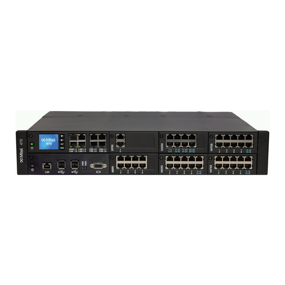
2. 2 Communication server Mitel 470 is a powerful communication server in the MiVoice Office 400 family. It is de- signed for installation in a 19” rack, but can also be set up on a flat surface. With the exception of the power supply and earthing, all the connections and control el- ements are accessible from the front. -
Page 19: Positioning
Applications range from small businesses or branches to large companies at one or more locations. Up to 36 users can be operated on the Mitel 470 communication server without licensing. And with an expansion licence up to 400 users are possible. - Page 20 MiVoice Office 400 communication platforms can be used to network up to 100 other Mitel sys- tems or SIP-compatible third-party systems. All the main telephony features such as call number and name display, enquiry call, hold, brokering, call transfer and confer- ence circuits are supported.
-
Page 21: Mitel System Phones And Clients
System Overview 2. 4 Mitel system phones and clients Mitel system phones stand out by virtue of their high level of user convenience and their attractive design. The broad range of products ensures there is a suitable model for every use. - Page 22 MiVoice Office 400 integra- switch for connecting a PC SIP Phone tion. Mitel 6735 SIP , Mitel 6737 SIP and • XML browser compatible Mitel 6739 SIP: • Automatic update of the terminal soft- • Integrated 1 Gbit Ethernet switch...
- Page 23 System Overview Tab. 4 SIP Multimedia Terminal Mitel BluStar 8000i Product Main features • Intelligent multimedia terminal with intuitive operation • Video conferencing solution, collaboration tool and application platform in one. • XML browser compatible • Bluetooth interface • Can be connected to a laptop •...
- Page 24 • All the system features can be used • FMC client for mobile phones (runs on various operating systems) • Integrates the mobile phone into the Mitel communication system • User is always reachable under the same call number (One Number con-...
- Page 25 Dialog 4222 interface • Hands-free feature • Powered via DSI bus or via optionally • Configurable team keys power supply Dialog 4223: • Wall mounting possible • 4 softkeys Dialog 4223 Mitel 470 as of R4.1 syd-0585/1.2 – R4.1 – 08.2016...
- Page 26 (can be used with Mitel SIP-DECT only). Note: The Mitel 610 DECT, Mitel 620 DECT, Mitel 630 DECT, Office 135/135pro and Office 160pro/Safeguard/ATEX cordless system phones are supported as before (not all system features can be used). Tab. 10...
-
Page 27: Various Phones, Terminals And Equipment
System Overview 2. 5 Various phones, terminals and equipment Thanks to the use of international standards other clients, terminals and phones, Mitel and third-party, can be connected and operated on the communication server: • SIP-based phones With the integrated SIP protocol SIP-based phones (softphones, hardphones) - or via an SIP access point also WLAN and DECT phones - can be connected to the communication server. -
Page 28: Solutions
A distinction is made among applications between Mitel-specific applications and certi- fied applications supplied by third parties. The Mitel applications Mitel Open Interfaces Platform (OIP) and Mitel 400 CCS run ei- ther on the integrated applications server or on a customer server. The fax service is offered on the integrated application server only. -
Page 29: Mitel Applications
• Secure instant messaging (IM) and data transmission • Audio, web and video conferences • Mitel 400 CCS is an additional application for the Mitel 400 Call Center, and provides statistics / reporting functions and agent monitoring (CCS = call Mitel 400 CCS centre supervision). - Page 30 • The alarm can be set off via a nurse call or fire-alarm system (ESPA inter- face), via a key predefined on the Mitel DECT or system phone, an alert but- ton, web client, or by calling the alarm server (audio guide), or via e-mail (subject line analysis).
- Page 31 Secure IP Remote • No router and firewall configuration or VPN connection setup required Management (SRM) • Allows configuration via WebAdmin once the connection has been set up • No installation necessary Mitel 470 as of R4.1 syd-0585/1.2 – R4.1 – 08.2016...
-
Page 32: Application Interfaces
Application interfaces The most important interface for own and third-party applications is the interface of the Mitel Open Interfaces Platform (OIP). This open interface allows the applications to be deeply integrated with telephony. Third-party applications can also be integrated on MiVoice Office 400 series systems via different interfaces without OIP. - Page 33 OIP as call center The powerful Mitel 400 Call Center is an integral part of OIP and provides all the main features such as flexible routing algorithms (cyclical, linear, longest time available, CLIP-based, last agent), skill-based agent groups as well as an analysis of the call centre data (online and offline) with chart-based evaluation.
- Page 34 System Overview Mitel 400 CCS is an extension of the Mitel 400 Call Center and offers several possibil- ities of statistically evaluating the call centre operation. Offline and online reports ena- ble the call center operator to analyse and optimise call centre operations.
-
Page 35: Message And Alarm Systems
The Mitel Alarm Server is a flexible solution which can be used in all sectors to process and record alarms. It can be used, for instance, in old people's nursing homes and as- sisted-living homes, as well as in other different facilities such as hotels, industrial plants, shopping centres, schools or administrations. -
Page 36: Cti - Computer Telephony Integration
MiVoice Office 400 supports First-Party CTI on all system phones via the Ethernet in- terface. For this purpose the First-Party TAPI Service Provider (AIF-TSP) is required. For first-party CTI applications which use the CSTA protocol (for instance Mitel Dialer), the ECSTA driver (Mitel CSTA-to-TAPI Link) is required. -
Page 37: Isdn Interface
In addition phones on ISDN and analogue interfaces can also be monitored. PC and phone allocation is handled by the telephony server. The third-party CTI connection is effected via Ethernet using the Mitel Open Interfaces Platform (OIP). To this end the OIP is installed on the telephony server. Third-party connections via Ethernet with CSTA are also possible. -
Page 38: Call Logging
Configuration is via WebAdmin. The MiVoice 5380 / 5380 IP reception phone or the web-based Mitel 400 Hospitality Manager application is available to operate the functions. A connection to a Property Management System (PMS) via the communica- tion server's Ethernet interface is also possible. -
Page 39: Connection Options
Keyboard, mouse, etc. Applications server Open Interfaces Platform (OIP) Ethernet Telephony Web Interface (TWP) Messaging and Alarm Systems Hotel Management Systems Fig. 4 Overview of interfaces with possible terminal equipment Mitel 470 as of R4.1 syd-0585/1.2 – R4.1 – 08.2016... -
Page 40: Expansion Stages And System Capacity
Fig. 5 Overview of the expansion possibilities The basic system Mitel 470 can be expanded not just with interface cards and system modules but also with an applications card (CPU2). The applications card is supplied with preinstalled operating system, unified communications and multi-media applica- tions. -
Page 41: Basic System
With the FOP fan-out-panel they can be split again to individual sockets. The Mitel 470 basic system has an integrated fan. The operating reliability of the com- munication server can be increased by fitting an optional redundant fan unit. -
Page 42: Interfaces, Display And Control Elements
Fig. 7 Mitel 470 basic system fitted with a redundant fan unit 3. 2. 1 Interfaces, display and control elements The interfaces accessible from the outside are located on the front and rear side of the basic system. - Page 43 The call manager card comprises two powerful DSP chips, one of which can be as- signed selectable functions. Two DSP modules can also be fitted as an option to fur- ther boost the media resources (see also "Media resources", page 48). Mitel 470 as of R4.1 syd-0585/1.2 – R4.1 – 08.2016...
- Page 44 LED on the On/Off button (see also "Call-Manager display and control panel", page 216). The figure below shows the positions of the interfaces and of the display and control el- ements on the call manager card. [10] Mitel 470 as of R4.1 syd-0585/1.2 – R4.1 – 08.2016...
-
Page 45: Power Supply
Power supply Internal power supply unit PSU2U The Mitel 470 communication server is powered as standard directly with a mains ca- ble. The voltage converter needs to be set to the correct position to match the mains power (230 VAC or 115VAC) (see also "Powering the communication server", page 102). - Page 46 Mains power 115/230 VAC Fig. 10 Overview of the Mitel 470 power supply concept Notes – It is also possible to operate the communication server with the external power supply unit APS2 only In this case redundancy operation is of course no longer possible.
-
Page 47: Ethernet Concept
3. 2. 3 Ethernet concept Mitel 470 provides three GBit Ethernet interfaces, which are routed to the front panel of the call manager card. They are used to connect to the customer’s data network (LAN) and e.g. the IP connection with an SIP provider. The socket marked "WAN" currently has no function and remains covered. -
Page 48: Media Resources
5) Can be used without licence subject to the following restrictions: Voice memory capacity approx. 20 minutes, no e-mail notification in the event of new voice messages, no forwarding of voice messages, no call record- ing, restricted voice mail menu by remote retrieval. Mitel 470 as of R4.1 syd-0585/1.2 – R4.1 – 08.2016... -
Page 49: Expansion With Cards And Modules
3. 3 Expansion with cards and modules An Mitel 470 basic system can be individually expanded using interface cards, system modules and an application card. The number and position of the available slots are described in the chapter "Interfaces, display and control elements", page 42. - Page 50 SIP/IP phone and a digital system phone or e.g. for an external user who is routed to the internal Voice Mail System via an SIP network interface. In an AIN VoIP chan- Mitel 470 as of R4.1 syd-0585/1.2 – R4.1 – 08.2016...
- Page 51 The number of configurable audio channels depends on the type of DSP chip (see "Configuration of DSP chips", page 55). Note On the Mitel 470 communication server G.711 audio channels are always used for audio services. The Voice mail mode parameter can therefore not be changed for this system.
- Page 52 Sufficient transmitters / receivers are already available for 1 PRI interface on the DSP of the Call Manager card (see Tab. 16). If this is not sufficient, additional senders/receivers can be configured with this setting. Mitel 470 as of R4.1 syd-0585/1.2 – R4.1 – 08.2016...
- Page 53 In normal operation all IP endpoints are registered with the • Conversation recording master, even if they are located on the satellite. • Announcement with audio file • Queue with announcement • Conference bridge Mitel 470 as of R4.1 syd-0585/1.2 – R4.1 – 08.2016...
- Page 54 No audio channels can be reserved for conference bridges. Audio channels from the Non-reserved/shared pool are always used for the conference bridge. Announcement service and music on hold use their own resources. Mitel 470 as of R4.1 syd-0585/1.2 – R4.1 – 08.2016...
- Page 55 • G.711: 8 channels • Secure G.711: 7 channels • G.711/G.729: 6 channels • Secure G.711/G.729: 5 channels Only for VoIP mode G.711 G.711/G.729 Only for VoIP mode G.711 G.711/G.729 Mitel 470 as of R4.1 syd-0585/1.2 – R4.1 – 08.2016...
- Page 56 – The system has to be restarted for the configuration changes of the DSP to take effect. – After a first start all the DSP chips are configured on DECT. 1) Although no longer available, the module is still supported. Mitel 470 as of R4.1 syd-0585/1.2 – R4.1 – 08.2016...
-
Page 57: Ip Media Module
Tab. 24 Max. number of voice channels per IP media module G.711 only, G.711/G.729, Type FoIP (T.38) Secure G.711 Secure G.711/G.729 EIP1-8 EIP1-32 Mitel 470 as of R4.1 syd-0585/1.2 – R4.1 – 08.2016... -
Page 58: Call Charge Modules
They are listed both among the trunk cards and the terminal cards. Up to 2 IP media modules can be fitted on PRI cards. Mitel 470 as of R4.1 syd-0585/1.2 – R4.1 – 08.2016... -
Page 59: Trunk Cards
(PRI: Primary Rate Interface) or BRI interfaces (BRI: Basic Rate Interface). BRI cards contain both network interfaces (BRI-T) and terminal interfaces (BRI-S). On the BRI cards 4 interfaces can be individually configured to BRI-S or BRI-T. Mitel 470 as of R4.1 syd-0585/1.2 – R4.1 – 08.2016... -
Page 60: Terminal Cards
Terminals to ETSI standard are connected via BRI cards. The cards contain both termi- nal interfaces (BRI-S) and network interfaces (BRI-T). On the BRI cards 4 interfaces can be individually configured to BRI-S or BRI-T. Mitel 470 as of R4.1 syd-0585/1.2 – R4.1 – 08.2016... - Page 61 • All interfaces configurable to BRI-T 4 × BRI-S 8BRI • Four fixed BRI-T interfaces • 4 BRI-S interfaces configurable to BRI-T 1) 1 fewer card if CPU2 application card is fitted Mitel 470 as of R4.1 syd-0585/1.2 – R4.1 – 08.2016...
-
Page 62: Applications Card Cpu2-S
The applications card is connected with the call manager call via Ethernet and the backplane, which means that the Ethernet interface on the front panel is not required. The Mitel Mitel Open Interfaces Platform (OIP) applications and a fax service are al- ready pre-installed on the application card standard PC. -
Page 63: System Capacity
Note: The values in the following three tables relate to a communication server with an Mitel 470 Expansion expansion licence. Without this licence the system is limited to the first 36 users in the numbering plan, which means many values in the table are not valid. - Page 64 Members per trunk grooup "large" Abbreviated dialling numbers + PISN users 4000 4000 Line keys per key telephone (except Mitel 6700 SIP / 6800 SIP) Line keys per key telephone on Mitel 6700 SIP / 6800 SIP 2...12 2...12 Line keys per CDE on Mitel 6700 SIP / 6800 SIP Total line keys on Mitel 6700 SIP / 6800 SIP Mitel 470 as of R4.1...
- Page 65 Busy lamp field keys on Mitel SIP phones in total 4000 4000 Busy lamp field keys per Mitel SIP phone Same users on busy lamp field keys on Mitel SIP phones Configured keys 12000 12000 Mitel 470 as of R4.1...
- Page 66 1) Without expansion licence limited to 36 users 2) For Russia maximum 256 users 3) Only 1 operator console, 1 MiVoice 2380 IP, 1 BluStar 8000i , 1 Mitel BluStar for PC, 1 Mitel SIP-DECT and 2 DECT- cordless phones are possible for each user.
-
Page 67: Terminals
DHCP clients on the internal DHCP server IP terminals MiVoice 2380 IP MiVoice 5360 IP MiVoice 5361 IP MiVoice 5370 IP MiVoice 5380 IP IP operator consoles / IP operator MiVoice 5380 IP applications MiVoice 1560 Mitel 470 as of R4.1 syd-0585/1.2 – R4.1 – 08.2016... - Page 68 • Radio units for cordless phones • Door intercoms with DTMF control functions • Group 3 fax machines • Answering machines • Modems External audio equipment with line output 1 per node Mitel 470 as of R4.1 syd-0585/1.2 – R4.1 – 08.2016...
-
Page 69: Terminal And Network Interfaces
2) Licences required 3. 4. 5 Software assurance Software Assurance (SWA) is Mitel’s comprehensive support offer which gives access to new software releases, support services and SRM remote access to the communi- cation server. The software assurance agreement has a fixed runtime and defines the number of au- thorised users on the communication system. -
Page 70: Licences
The Mitel CPQ application automatically plans the nec- essary licences, which are then enabled on the communication server using a licence code. - Page 71 Note: The purchase of a new communication server also includes a software assurance for a spe- cific period. Log on with your partner login to Mitel Connect https://connect.mitel.com obtain a new licence code using the EID number and the voucher. The licence code issued...
- Page 72 Mitel Advanced Intelligent Network In an AIN with an Mitel 470 as Master and more than 36 users, an Mitel 470 Expansion licence is required only for the Master. The Mitel 470 satellites do not need a licence, even if they have more than 36 users (except of course for offline operations lasting more than 36 hours).
- Page 73 In the event of failure of the primary communication server or an interruption in the IP connection to the primary communication server, SIP phones in the Mitel 6700 SIP / 6800 SIP series can automatically register on a backup communi- cation server. On the backup communication server one licence is required per phone.
- Page 74 One licence is required per system /AIN. Features • Secure VoIP This licence allows encrypted VoIP connections with the aid of SRTP (Secure Real- Time Transport Protocol) and TLS (Transport Layer Security). Mitel 470 as of R4.1 syd-0585/1.2 – R4.1 – 08.2016...
- Page 75 • VoIP Channels for Standard Media Switch Note: This licence is required for Mitel 415/430 and Mitel 470 only. For Virtual Appliance, the VoIP channels of the integrated Mitel Media Server are made available and do not require any licences.
- Page 76 • G.729 Codec This licence allows the use of a G.729 codec for the voice channel of Mitel SIP phones, IP system phones and SIP network interfaces (also for SIP networking). The licences are always used wherever they are required. Mitel SIP-DECT and standard SIP terminals do not require this licence.
- Page 77 CPU2 Fax Clients Additional users configurable with fax mailbox. • Mitel Dialer This licence allows you to use the Mitel Dialer CTI application. The number of li- cences determines the simultaneously active, user-assigned Mitel Dialer applica- tions. • Hospitality Manager This licence allows you to use the Mitel 400 Hospitality Manager.
- Page 78 Redkey). ATASpro Interface licence can also be used to determine the position of users of Mitel DECT cordless phones, which can be viewed with the appropriate applica- tions. Mitel 470 as of R4.1 syd-0585/1.2 – R4.1 – 08.2016...
-
Page 79: Restricted Operating Mode
Expansion Stages and System Capacity Note: If you use the Mitel Open Interfaces Platform, OIP takes the licences from the communica- tion server. So always acquire these licences for the communication server so you can use ATAS even without OIP. -
Page 80: Temporary Offline Licences
Users Basic User Licence bundle: Limited only by the In the AIN, – – User licence system capacity only on the 1 phone licence (any one) Master; otherwise per node. Mitel 470 as of R4.1 syd-0585/1.2 – R4.1 – 08.2016... - Page 81 ✓ Mitel SIP Terminals Number of registered 1, 20 or 50 additional In the AIN, Mitel SIP terminals Mitel SIP terminals per only on the licence Master; otherwise per node. Mitel 470 as of R4.1 syd-0585/1.2 – R4.1 – 08.2016...
- Page 82 ✓ ✓ Mitel 8000i Video Use of the video function- Additional licence for In the AIN, Options ality of an Mitel SIP termi- Mitel SIP Terminals. 1, only on the 20 or 50 additional Master; Mitel SIP terminals otherwise with video functionality per node.
- Page 83 SRTP and encrypte sion TLS. d trans- mission Silent Intrusion Use of the Silent intrusion Locked Enabled In the AIN, – – feature only on the Master; otherwise per node. Mitel 470 as of R4.1 syd-0585/1.2 – R4.1 – 08.2016...
- Page 84 – – one satellite Master Mitel AIN Satellites Additional satellite in an Additional licence for Only on the – – Base Mitel AIN. 1 addi- Master tional satellite per licence Mitel 470 as of R4.1 syd-0585/1.2 – R4.1 – 08.2016...
- Page 85 In the AIN, Basic Package site for all other only on the OpenCount licences. Master; Enables connection to the otherwise MiVoice Office 400 and per node. the use of basic functions. Mitel 470 as of R4.1 syd-0585/1.2 – R4.1 – 08.2016...
- Page 86 "General system Master; capacity", page 63) otherwise per node. interfaces ✓ ATAS Interface Use of the ATAS interface Locked Enabled In the AIN, – only on the Master; otherwise per node. Mitel 470 as of R4.1 syd-0585/1.2 – R4.1 – 08.2016...
- Page 87 3) If Virtual Appliance is used as Master, the VoIP channels of the master node are made available without a li- cence from the integrated Mitel Media Server. However, for the satellites' VoIP channels, the licences must be purchased.
-
Page 88: Power Supply Capacity
OIP licences OIP licences are managed by OIP itself. A detailed description of the OIP licences can be found in the System Manual Mitel Open Interfaces Platform. 3. 4. 10 Power supply capacity The maximum number of terminals connected to the system can be limited by the sup- ply power available for terminals. - Page 89 – Line length: 200 m The table below shows the average power requirements of the terminals for a line length of approx. 200 m and a wire diameter of 0.5 mm. Mitel 470 as of R4.1 syd-0585/1.2 – R4.1 – 08.2016...
- Page 90 5) The value applies to phones with hardware version "-2". The value for phones with hardware version "-1" is 60 mW lower. 6) The value depends greatly on the terminal type. With the planning application Mitel CPQ the power supply available for terminals is checked automatically. Mitel 470 as of R4.1...
-
Page 91: Power Supply Per Interface
• Terminals used incl. auxiliary devices • Bus configuration • Line length and conductor cross-section For information on the calculations refer to "Terminal interfaces", page 127. Mitel 470 as of R4.1 syd-0585/1.2 – R4.1 – 08.2016... -
Page 92: Installation
Installation Installation This Chapter tells you how Mitel 470 can be installed and the conditions to be ob- served. It also includes the mounting into a 19” rack, the correct way to connect the earthing, and the power supply. Other topics in this chapter include how to fit sys- tem modules and interface cards. -
Page 93: Fitting The Communication Server
Installation 4. 2 Fitting the communication server The Mitel 470 communication server is designed for installation in a 19” rack (2 height units). The communication server can also simply be placed on a flat surface. Wall- mounting is not allowed. -
Page 94: Safety Regulations
Always touch the earthed metal case of the communication server before carrying out work inside the housing. This also applies to interface cards and system modules that are no longer packed inside the ESD protective wrapping. Mitel 470 as of R4.1 syd-0585/1.2 – R4.1 – 08.2016... -
Page 95: Flow Of Hot Air
4. 2. 4 Flow of hot air The Mitel 470 communications server comes with a fan already pre-installed. The housing is designed so the air flow is first guided at two levels over the processor cards and the interface cards, then passes through cutouts in the backplane, absorbs the heat from the power supply unit, and exits the housing through the fan aperture. -
Page 96: Desktop Installation
4. 2. 6 Rack-mounting The rack mounting of the Mitel 470 communication server allows it to be installed hori- zontally in a 19” rack. Be sure to observe the following: • The communication server takes up the space of 2 height units inside the 19” rack. -
Page 97: Fitting An Additional Fan
Fans have a limited service life. So if a fan fails become of age ( approx. 5 years) it is advisable to replace both fans as a precautionary measure. Materials required: • Mitel 470 additional fan premounted on fastening frame • Set of screws for additional fan • Screwdriver To install the additional fan proceed as follows: 1. - Page 98 Redundant fan unit Fastening frame Fig. 19 Fitting the additional fan in Mitel 470 How to make backplane BP2U sit correctly When the rear housing cover is open (e.g. so an additional fan can be installed), the backplane can spring out from the lower guide carriages (above all if no card is installed).
- Page 99 Backplane (BP2U) Must be flush 4 bottom guide slots 3 fastening brackets with contact springs 4 top guide slots Upper rear housing cover Fig. 20 Correct sitting of backplane BP2U Mitel 470 as of R4.1 syd-0585/1.2 – R4.1 – 08.2016...
-
Page 100: Earthing And Protecting The Communication Server
The communication server’s earthing connection is located on the rear panel of the communications server next to the mains power socket. The earthing wire is secured using a screw and a spring washer. Fig. 21 Earthing connection Mitel 470 as of R4.1 syd-0585/1.2 – R4.1 – 08.2016... -
Page 101: Connecting The Cable Screening
Note Connect the cable screens to one another at the splitting point only. Observe the tree structure principle to prevent earth loops. Mitel 470 as of R4.1 syd-0585/1.2 – R4.1 – 08.2016... -
Page 102: Powering The Communication Server
Europe), and with 20 A maximum in countries with 115 V mains power (e.g. in North America). The overview table below lists the four different types of power supply with the availa- ble power outputs: Mitel 470 as of R4.1 syd-0585/1.2 – R4.1 – 08.2016... -
Page 103: Internal Power Supply Unit
Suitable for a typical system configuration external auxiliary power sup- with power supply redundancy ply unit External auxiliary power sup- 240 Watt Minor heat generation inside the Mitel 470 ply unit only housing Internal power supply unit + 360 Watt Suitable for maximum power requirements... - Page 104 6 screws. If a fan-out-panel FOP or EFOP is already fitted, the auxil- iary power supply can be installed behind the connection panel. The following diagram shows the fan-out-panel FOP from below with the auxiliary power supply fitted. Mitel 470 as of R4.1 syd-0585/1.2 – R4.1 – 08.2016...
-
Page 105: Uninterruptible Power Supply (Ups)
The uninterrupted operation of the communication server is ensured if the UPS takes over the power supply within 20ms of the mains outage. See also For more technical details see "Technical data", page 256. Mitel 470 as of R4.1 syd-0585/1.2 – R4.1 – 08.2016... -
Page 106: Equipping The Basic System
4. 5 Equipping the Basic System For individual expansion the Mitel 470 basic system can be fitted with interface cards, system modules and an application card. An overview can be found in the Chapter "Expansion Stages and System Capacity", page 40. -
Page 107: Equipping The Call Manager Card Cpu1
(DSP module, IP Media module, call charges module). The RAM mod- ule only needs to be replaced in the event of repairs or maintenance work (see "Oper- ation and Maintenance", from page 195). Mitel 470 as of R4.1 syd-0585/1.2 – R4.1 – 08.2016... -
Page 108: Fitting Dsp Modules
8. Secure the Call Manager card back into its slot with the screw. 9. Restart the call manager by pressing the On/Off button on the call manager card. Mitel 470 as of R4.1 syd-0585/1.2 – R4.1 – 08.2016... -
Page 109: Fitting Ip Media Modules
8. Restart the call manager by pressing the On/Off button on the call manager card. Proceed accordingly to fit one or two IP Media modules to a PRI trunk card. Mitel 470 as of R4.1 syd-0585/1.2 – R4.1 – 08.2016... -
Page 110: Fitting Call Charge Modules
7. Use the screw to secure the FXO card back into its slot. 8. Restart the call manager by pressing the On/Off button on the call manager card. Mitel 470 as of R4.1 syd-0585/1.2 – R4.1 – 08.2016... -
Page 111: Component Mounting Rules
– The interfaces are enabled in accordance with their designation, starting with the lower designations. This means that the terminal interfaces on the processor card are always enabled before those on the interface cards. Mitel 470 as of R4.1 syd-0585/1.2 – R4.1 – 08.2016... -
Page 112: Connecting The Communication Server
There are two possibilities for connecting the communication server indirectly to the telephone network and terminal-side cabling: • Connection via main distribution board • Connection to a universal building cable installation (UBC) Mitel 470 as of R4.1 syd-0585/1.2 – R4.1 – 08.2016... -
Page 113: Connection Via Main Distribution Board
With terminal cards with 16 or more interfaces some or all of the RJ45 sockets are as- signed four-fold on the front panel of the Mitel 470. With this cable they can be con- nected without the use of a fan-out-panel (FOP). The cable is 6 m long and at one ex- tremity has four RJ45 connectors on which all the pins are wired. - Page 114 121 and "Connection of Ethernet interfaces", page 157). Use standard commercial connecting cables not just for the PRI and Ethernet interfaces but also for connecting the BRI-T interfaces. Mitel 470 as of R4.1 syd-0585/1.2 – R4.1 – 08.2016...
- Page 115 – turquoise – violet – – blue – turquoise – violet – – orange – turquoise – violet – View A View B Fig. 31 Pin numbering, RJ45 connector Mitel 470 as of R4.1 syd-0585/1.2 – R4.1 – 08.2016...
-
Page 116: Connection To A Universal Building Cable Installation (Ubc)
Connecting to a UBC via a (main) distribution board (example) Communica- tion server User Patch panel User side Phone Phone Exchange side Public exchange Fig. 33 Connecting to a UBC via wiring centre (example) Mitel 470 as of R4.1 syd-0585/1.2 – R4.1 – 08.2016... -
Page 117: Cabling Interfaces
A port address is always of the type x.y. x is the number of the card slot, and y, the port number. The slot numbering starts with 1 and ends with 8 (see "Number of the Mitel 470 slots", page 106). - Page 118 BRI basic rate interface network-side Mains power Communica- tion server BRI-T BRI-T Exchange Do not connect power supply NT1 Do not fit the jumper Fig. 36 Basic access on NT1 Mitel 470 as of R4.1 syd-0585/1.2 – R4.1 – 08.2016...
- Page 119 Cable cores Basic access BRI-S Basic rate interface BRI-T ext. Bus configuration BRI-S is subject to the conditions that apply to terminal interface BRI-S (see "BRI-S ext. terminal interfaces", page 136). Mitel 470 as of R4.1 syd-0585/1.2 – R4.1 – 08.2016...
-
Page 120: Primary Rate Interface Pri
With card 1PRI the PRI interface is routed in parallel to both RJ45 sockets for test pur- poses. Notes – In normal operation both sockets must not be connected on the 1PRI card; otherwise faults may occur. – Circuit type as per EN/IEC 60950: SELV Mitel 470 as of R4.1 syd-0585/1.2 – R4.1 – 08.2016... - Page 121 – – – – – – – 1) Other designations are also possible on the NT1 such as: "S2m ab" instead of "TxA/TxB" and "S2m an" in- stead of "RxA/RxB". Mitel 470 as of R4.1 syd-0585/1.2 – R4.1 – 08.2016...
- Page 122 — — — — — — — — Transmission facilities PINX 1 PINX 2 max. max. 200 m 200 m Fig. 42 Primary rate interface, networked with transmission equipment Mitel 470 as of R4.1 syd-0585/1.2 – R4.1 – 08.2016...
- Page 123 — — — — — — Leased-line or dial-up PINX 1 PINX 2 connection Mains power Mains power Fig. 43 Primary rate access PRI, networked with leased-line or dial-up connection Mitel 470 as of R4.1 syd-0585/1.2 – R4.1 – 08.2016...
-
Page 124: Fxo Network Interfaces
On cards with 16 interfaces RJ45 sockets 9 to 16 are multiply assigned. The signals can be split again to individual RJ45 sockets using patch cables and the fan-out panel Mitel 470 as of R4.1 syd-0585/1.2 – R4.1 – 08.2016... - Page 125 Connection Assignment of the RJ45 sockets on the front panel: Tab. 54 Connection FXO network interface Communication server Public analogue network FXO signal Socket – – – – – – Mitel 470 as of R4.1 syd-0585/1.2 – R4.1 – 08.2016...
- Page 126 FXO signal FXO signal Socket necting cables – – – – – – – – – – – – – – – – – – – – – – – – Mitel 470 as of R4.1 syd-0585/1.2 – R4.1 – 08.2016...
-
Page 127: Terminal Interfaces
FOP (see "Fan-out panel FOP", page 148) or with 8-fold as- signed connecting cables (see e.g. Prefabricated system cable 4 x RJ45). Multiply assigned RJ45 sockets are colour-coded in blue. Note Circuit type as per EN/IEC 60950: SELV Mitel 470 as of R4.1 syd-0585/1.2 – R4.1 – 08.2016... - Page 128 Connection of individually assigned DSI terminal interface Communication server Cable cores Connection socket Socket DSI signal DSI signal Socket – – – – – – – – – – – – Mitel 470 as of R4.1 syd-0585/1.2 – R4.1 – 08.2016...
- Page 129 Socket DSI signal DSI signal Socket – – – – – – – – – – – – – – – – – – – – – – – – Mitel 470 as of R4.1 syd-0585/1.2 – R4.1 – 08.2016...
- Page 130 DSI-DASL interface. The maximum line length for a 0.5 mm wire diameter is set at 1000 m. 1) Office 10, Office 25, Office 35, Office 45/45pro are supported as before Mitel 470 as of R4.1 syd-0585/1.2 – R4.1 – 08.2016...
- Page 131 4) An MiVoice M535 always requires a power supply unit 5) The value applies to radio units with hardware version "-2". The value for hardware version "-1" is 300 mW lower. Mitel 470 as of R4.1 syd-0585/1.2 – R4.1 – 08.2016...
- Page 132 Fig. 47 Power available A on the DSI-AD2 bus Power available B: Applies to the SB-4+/SB-8 DECT radio units with hardware version "-2" and system phones of the Dialog 4200 series. Mitel 470 as of R4.1 syd-0585/1.2 – R4.1 – 08.2016...
- Page 133 The maximum power available is also determined based on the calculated line length (assumption: Diameter = 0.5 mm). If the calculated power available is below the maximum possible power input of the connected system phones, the message Mitel 470 as of R4.1 syd-0585/1.2 – R4.1 – 08.2016...
- Page 134 • Maximum line length for a wire diameter of 0,6 mm: 1170 m Example 3: Evaluation of an existing line installation Line diameter: 0.5 mm Loop resistance: 120 Ω Fig. 47 indicates: • Line length: 660 m • Power available: 2120 mW Mitel 470 as of R4.1 syd-0585/1.2 – R4.1 – 08.2016...
- Page 135 1) Note: max. 25 m can be crossed unstranded. (CH: Applies also to cable type G51) Installation rules • If an Mitel DECT radio unit is used, do not connect any other system phone to the same DSI bus. • If...
-
Page 136: Bri-S Terminal Interfaces
The S bus is a four-wire, serial ISDN bus based on the DSS1 protocol (ETSI standard). It starts in each case at an BRI-S interface of the communication server. Four bus con- figurations are possible, depending on the line length and the number of terminals: Mitel 470 as of R4.1 syd-0585/1.2 – R4.1 – 08.2016... - Page 137 150 m Fig. 51 S bus, short, V-shaped 4. Connection point Communica- 2 x 100 Ω tion server max. 20 m max. 500 m Fig. 52 S bus, long Mitel 470 as of R4.1 syd-0585/1.2 – R4.1 – 08.2016...
- Page 138 The number of terminals is the sum of the power requirements of the individual termi- nals and the power available on the S bus. Connection sockets RJ45, 8-pin Front view of RJ45 Fit resistors at bus extremity only Fig. 54 RJ45 connection, single socket Mitel 470 as of R4.1 syd-0585/1.2 – R4.1 – 08.2016...
- Page 139 < 125 Ω (100 kHz), < 115 Ω (1 MHz) Wave attenuation < 6 dB/km (100 kHz), < 26 dB/km (1 MHz) Near/crosstalk attenuation > 54 dB/100 m (1 kHz to 1 MHz) Mitel 470 as of R4.1 syd-0585/1.2 – R4.1 – 08.2016...
-
Page 140: Fxs Terminal Interfaces
On terminal cards with 16 or more interfaces some or all of the RJ45 sockets are multi- ply assigned. The signals can be split again to individual RJ45 sockets using patch ca- 1) Not possible within an AIN Mitel 470 as of R4.1 syd-0585/1.2 – R4.1 – 08.2016... - Page 141 Connection of individually assigned FXS terminal interface Communication server Cable cores Connection socket Analogue Analogue Socket Socket signal signal – – – – – – – – – – – – Mitel 470 as of R4.1 syd-0585/1.2 – R4.1 – 08.2016...
- Page 142 Analogue Analogue Socket Socket signal signal – – – – – – – – – – – – – – – – – – – – – – – – Mitel 470 as of R4.1 syd-0585/1.2 – R4.1 – 08.2016...
- Page 143 • Group 3 fax • Answering machines • Modem 1) Transmission with the T.38 protocol is recommended for Fax over IP. The corresponding media re- sources need to be allocated. Mitel 470 as of R4.1 syd-0585/1.2 – R4.1 – 08.2016...
- Page 144 In this mode 2-wire door intercoms with DTMF control functions can be connected. The no-load voltage in this mode is 24 VDC. The loop current is limited to 25 mA. Mitel 470 as of R4.1 syd-0585/1.2 – R4.1 – 08.2016...
- Page 145 "Music on hold" and then to store it as a wave file. line out FXS interface Fig. 59 Connection for FXS mode: External audio source Mitel 470 as of R4.1 syd-0585/1.2 – R4.1 – 08.2016...
- Page 146 There are no special requirements for the cables. Warning Control outputs must have a floating connection. max. 25mA 24 VDC FXS interface Fig. 60 Connection for FXS mode: Control output Mitel 470 as of R4.1 syd-0585/1.2 – R4.1 – 08.2016...
- Page 147 • The same switch group can only be switched by the 2 assigned control inputs. • Control of the switch groups using the control inputs takes priority over control using function codes. Mitel 470 as of R4.1 syd-0585/1.2 – R4.1 – 08.2016...
-
Page 148: Fan-Out Panel Fop
This card has 2 four-fold assigned RJ45 sockets. The 8 individually assigned RJ45 sockets are connected directly while the 2 four-fold assigned sockets are looped via the front panel of the fan-out-panel connector (FOP) strip using 2 patch cables. Mitel 470 as of R4.1 syd-0585/1.2 – R4.1 – 08.2016... - Page 149 Overview", page 254). The internal wiring of the fan-out panel is shown in the table below. The wiring is shown for sockets 1 - 4. Sockets 5 - 8 are wired accordingly. Mitel 470 as of R4.1 syd-0585/1.2 – R4.1 – 08.2016...
- Page 150 – – – – – – – – – – – – Socket The FOP fan-out-panel does not require a power supply; however in certain cases it must be earthed. Mitel 470 as of R4.1 syd-0585/1.2 – R4.1 – 08.2016...
-
Page 151: Emergency Fan-Out-Panel (Efop)
If for example ports are switched off due to overloading, the corresponding exchange lines switch over automatically and directly to the analogue phones. 1) Available as of R2.1 SP1 Mitel 470 as of R4.1 syd-0585/1.2 – R4.1 – 08.2016... -
Page 152: Detailed Description
Auxiliary power suply 1 … 8 1 … 8 unit (APS2) Communication server relevant only with APS2 auxiliary power supply unit in redundancy operation Fig. 67 Block diagram, EFOP fan-out-panel Mitel 470 as of R4.1 syd-0585/1.2 – R4.1 – 08.2016... - Page 153 On FXS or FXO interface cards with four-fold assigned RJ45 sockets, direct wiring to the FXS1-4 and FXO1-4 sockets of the EFOP fan-out-panel is possible. The unas- signed connection blocks can be used for other purposes. Mitel 470 as of R4.1 syd-0585/1.2 – R4.1 – 08.2016...
- Page 154 In redundancy operation of the communication server a power supply unit of the same type can also be connected to the second supply socket. The power supply unit is available separately (see "Equipment Overview", page 254). Mitel 470 as of R4.1 syd-0585/1.2 – R4.1 – 08.2016...
- Page 155 The EFOP fan-out-panel has 4 equivalent connections for the protective earthing (see Fig. 69). Warning Because analogue trunk lines are to be routed via the fan-out panel EFOP, for safety reasons the fan-out panel must be connected to the protective earth. Mitel 470 as of R4.1 syd-0585/1.2 – R4.1 – 08.2016...
-
Page 156: Ethernet Interfaces
4. 7. 6 Ethernet interfaces The communication server Mitel 470 has a Gbit Ethernet switch on the call manager card. Three LAN interfaces are routed to the front panel of the call manager card and labelled accordingly. The RJ45 sockets are highlighted in colour in the figure below. - Page 157 The IP addressing after a first start depends on whether a static IP addressing is al- ready stored on the EIM card from a previous configuration. A static IP addressing (IP address, subnet mask, gateway) entered manually is stored on the EIM card and re- Mitel 470 as of R4.1 syd-0585/1.2 – R4.1 – 08.2016...
- Page 158 Port has a connection with the network flashing 100 Mbit/s Port is receiving or sending data 1 Gbit/s Port has a connection with the network flashing 1 Gbit/s Port is receiving or sending data Mitel 470 as of R4.1 syd-0585/1.2 – R4.1 – 08.2016...
-
Page 159: Installing, Powering, Connecting And Registering Terminals
Headset socket Power supply socket for connecting a power supply if PoE is not available Connect expansion key module MiVoice M530⁄MiVoice M535 (available on MiVoice 5370 IP and MiVoice 5380 IP) Mitel 470 as of R4.1 syd-0585/1.2 – R4.1 – 08.2016... - Page 160 2) PD (Powered Device) = power consumer, e.g. an IP system phone 3) including an MiVoice M530 or MiVoice M535 expansion keypad 4) including up to three MiVoice M530 or MiVoice M535 expansion keypads Mitel 470 as of R4.1 syd-0585/1.2 – R4.1 – 08.2016...
-
Page 161: Mitel 6700 Sip / 6800 Sip Series Sip Phones
Mitel SIP phones are platform-independent phones with a wide range of features. They can also be perfectly integrated into one of the Mitel Platforms and used as a system phone. Mitel SIP Phones on MiVoice Office 400 first support MiVoice Office 400 fea- tures and have a separate user's guide. -
Page 162: Digital System Phones
Mitel 470 as of R4.1 syd-0585/1.2 – R4.1 – 08.2016... -
Page 163: Mivoice 5361 / 5370 / 5380
DHSG standard. Mounting the Bluetooth module The MiVoice 5380 can also be equipped with a Bluetooth module as an option. To in- stall (see Fig. 72), proceed as follows: Mitel 470 as of R4.1 syd-0585/1.2 – R4.1 – 08.2016... - Page 164 3. Connect the Bluetooth module. Make sure it is securely fitted (see ➂). 4. Fit the cover for the Bluetooth module back into place and press home until it snaps into place (see ➃). Mitel 470 as of R4.1 syd-0585/1.2 – R4.1 – 08.2016...
-
Page 165: Office 25, Office 35, And Office 45/45Pro
These system phones are desktop models. A wall-mounted bracket is available as an option for Office 25 and Office 35. Mounting the desktop model Connect the handset cord and the phone cord to the phone as indicated in the operat- ing instructions. Mitel 470 as of R4.1 syd-0585/1.2 – R4.1 – 08.2016... - Page 166 Connecting the expansion key module or the alphanumerical keyboard The connection of the expansion key modules and the alphanumerical keyboard to Office 35 and Office 45 is described in the relevant operating instructions. Mitel 470 as of R4.1 syd-0585/1.2 – R4.1 – 08.2016...
- Page 167 Installation Fig. 73 Wall mounting of Office 25 and Office 35 Mitel 470 as of R4.1 syd-0585/1.2 – R4.1 – 08.2016...
-
Page 168: Office 10
4. Label terminal. Fig. 74 Set the DSI bus address Note: Make sure the TSD (address switch) is pushed in as far as the stop or the switchover will not function correctly. Mitel 470 as of R4.1 syd-0585/1.2 – R4.1 – 08.2016... -
Page 169: Dect Radio Units And Cordless Phones
• Avoid exposure to chemicals. • Avoid direct sunlight. • See also technical data in Tab. 123. Note: If these requirements cannot be met (e.g.outdoor installation), use the appropriate protective housing. Mitel 470 as of R4.1 syd-0585/1.2 – R4.1 – 08.2016... -
Page 170: Installing The Radio Units
Office 135 charging bay. ø screw : 4 mm Mounting bracket All dimensions in mm Fig. 75 Dimensional drawing for wall-mounting the mounting bracket Mitel 470 as of R4.1 syd-0585/1.2 – R4.1 – 08.2016... - Page 171 Installation distances Connecting the radio unit 115/230 VAC (optional) DSI interface Socket 1 Socket 2 Sockets, external antennas ( SB-8ANT only) Fig. 77 Underside of the radio units with connection points Mitel 470 as of R4.1 syd-0585/1.2 – R4.1 – 08.2016...
-
Page 172: Analogue Phones Mitel 6710 Analogue, Mitel 6730 Analogue
Fault not flashing and not lit LED switched off or radio unit defective or not in operation For further display variants, see "Operating state of the Mitel DECT radio units", page 246 4. 8. 8 Analogue phones Mitel 6710 Analogue, Mitel 6730 Analogue The phones can be used as desktop model or as wall model. - Page 173 No symbol (Any switch setting) The red MWI LED under the notification key can only be controlled with the Mitel 470 communication server and the notification type Polarity reversal. Set the switch on the underside of the phone to the symbol "−". This applies to a straight connecting cable (provided with the phone).
- Page 174 Configuring keys Configure the keys on analogue phones Mitel 6700 Analogue in the WebAdmin termi- nal configuration. The phone must be connected during configuration so the key con- figuration can be stored on the phone immediately.
-
Page 175: Configuration
Office 400 series communication servers. It offers a simple, user-friendly interface and an online help, and with its different authorization levels it is aimed at different user groups: Fig. 78 WebAdmin Configuration Tool Mitel 470 as of R4.1 syd-0585/1.2 – R4.1 – 08.2016... - Page 176 The Hospitality Administrator features all the views required to set up the Mitel 400 Hospitality Manager and the reception menu of the MiVoice 5380 / 5380 IP and specify its default settings. A link can also be used to start the Mitel 400 Hospitality Manager (see "Mitel 400 Hospitality Manager", page 177).
-
Page 177: Integrated And Auxiliary Applications
Integrated and auxiliary applications Mitel 400 Hospitality Manager The Mitel 400 Hospitality Manager is a web-based application for receptionists in the hospitality sector. It provides a clear, at-a-glance list view or floor-by-floor view of the rooms and features functions such as check-in, check-out, notification, wake-up call, retrieval of call charges, maintenance list, etc. - Page 178 • Windows user name + PIN • Windows user name + password The standard PIN "0000" is accepted, but must be changed during first login. You can choose any 2 to 10-digit number combination. Mitel 470 as of R4.1 syd-0585/1.2 – R4.1 – 08.2016...
- Page 179 You can modify its IP address or directly start the WebAdmin administration tool. Moreover, with System Search you can load language files for the audio guide, Mitel phones as well as for the user interface and online help of WebAdmin, Hospitality Man- ager and Self Service Portal via MiVoice Office 400 FTP server onto your PC and up- load them afterwards to the communication server with WebAdmin.
- Page 180 Note: For Virtual Appliance, System Search is only available for downloading language files for the audio guide, Mitel SIP terminals as well as for the WebAdmin, Hospitality Manager and Self Service Portal user interfaces and online help. Mitel 400 WAV Converter...
-
Page 181: Access Types
SRM agent. See also: You can find instructions on how to set up Secure IP Remote Management in the WebAdmin help on the IP remote management (SRM) view ( =mw). Mitel 470 as of R4.1 syd-0585/1.2 – R4.1 – 08.2016... -
Page 182: User Access Control
Access is PIN-protected (see "Call-Manager display and control panel", page 216). The predefined user account MMCC is meant for operating a Mitel Mobile Client Con- troller. The two predefined user accounts blustar... -
Page 183: Authorization Profiles
Authorization profiles can only be viewed or created by Administrators Expert mode. 5. 3. 2 Passwords To ensure that the communication server can only be configured by authorized person- nel, access to the configuration is password-protected. Mitel 470 as of R4.1 syd-0585/1.2 – R4.1 – 08.2016... -
Page 184: Password Syntax
If the passwords of all administrators are lost, access can still be gained locally without a password (see "Password-free access", page 185). Mitel 470 as of R4.1 syd-0585/1.2 – R4.1 – 08.2016... -
Page 185: Password-Free Access
The user account must also be assigned an authorization profile in which the interface access Remote maintenance dial-up access is enabled. This also applies to SRM (Secure IP Remote Management), secure IP remote management. Mitel 470 as of R4.1 syd-0585/1.2 – R4.1 – 08.2016... -
Page 186: Access Enabled By Local Users
It is possible to bar remote maintenance manually using #754 before it is initi- ated. Remote maintenance access can be enabled permanently using the function code *753. To bar access, the authorized user must enter the function code #753 manually. Mitel 470 as of R4.1 syd-0585/1.2 – R4.1 – 08.2016... -
Page 187: Function Keys For Remote Maintenance Access
The relevant LED lights up if remote maintenance access is enabled once or perma- nently. The relevant LED goes off as soon as remote maintenance access is denied again, ei- ther automatically or manually, using the function code or WebAdmin. Mitel 470 as of R4.1 syd-0585/1.2 – R4.1 – 08.2016... -
Page 188: Configuring
The configuration steps are based on the information determined during the planning and, where applicable, the installation. Whenever possible, use the planning and ordering software Mitel CPQ, to set up your communication system. Mitel CPQ can be operated online after logging in at Mitel Connect https://connect.mitel.com... -
Page 189: Configuration Notes
60 days. The trial licence’s expiry date is indicated under Status. This procedure can only be used once for each function or feature. Mitel 470 as of R4.1 syd-0585/1.2 – R4.1 – 08.2016... -
Page 190: File Management
In this view language files can be manually or automatically loaded for Mitel 6700 SIP / 6800 SIP SIP phones via FTP server. Moreover, you can manually or automatically load the languages for the WebAdmin, Hospitality Man- ager and Self Service Portal user interface and online help, as well as an external numbering plan for the SIP connection via the FTP server. -
Page 191: System Reset
Note that the licence code is dependent on the sales channel and that you can no longer use the existing licence code. Note: This function is only accessible for Administrators in Expert mode. Mitel 470 as of R4.1 syd-0585/1.2 – R4.1 – 08.2016... -
Page 192: Data Backup
File browser =2s) or with an FTP connection. A backup remains stored until the set storage time has expired; the .zip file is then de- leted from the file system. Mitel 470 as of R4.1 syd-0585/1.2 – R4.1 – 08.2016... -
Page 193: Distribution Service
See also: The procedure for creating and restoring a backup is described in detail in the WebAdmin help in the Data backup =um) view. Mitel 470 as of R4.1 syd-0585/1.2 – R4.1 – 08.2016... -
Page 194: Importing And Exporting Configuration Data
5. 6. 6 Mitel 6700 SIP / 6800 SIP phones Prior to the registration, reset any phones that were already in operation back to the factory setting. For security reasons, delete the phone's MAC address in WebAdmin. -
Page 195: Operation And Maintenance
• The data of applications on the applications server (if a CPU2-S applications card is fitted) is stored on a hard disk. Mitel 470 as of R4.1 syd-0585/1.2 – R4.1 – 08.2016... -
Page 196: System Software
You can see the file system memory load and then load audio data, languages for the user interface and online help, language files for Mitel 6700 SIP / 6800 SIP-series SIP phones as well as an external numbering plan for SIP connection. Moreover, with the file browser you have the possibility to view, upload, replace or delete the folders and files in the file system. -
Page 197: Boot Software
Access to the configuration data via WebAdmin is regulated by a User Access Control with user accounts, authorization profiles and authorization levels. More information can be found in the Chapter "User access control", page 182. Mitel 470 as of R4.1 syd-0585/1.2 – R4.1 – 08.2016... -
Page 198: Update Software
1. Access the configuration menu Settings. 2. Long-click on the * key Information can be retrieved on /Mitel 6700 SIP / 6800 SIP SIP phones as well as on /Mitel 600 DECT DECT phones via the menu. Depending on the phone, additional information is displayed. -
Page 199: Firmware For Corded System Phones
All other system phones have a Flash memory. SIP system phones The firmware for Mitel 6700 SIP / 6800 SIP series SIP phones as well as for Mitel BluStar 8000i, Mitel BluStar clients and Mitel Dialer is preferably located on a firmware server. -
Page 200: Firmware System Mivoice Office 400 Dect
There is only one firmware for the cordless Mitel 600 DECT series phones. It is in- cluded in the communication server's software package and stored in the file system of the communication server. -
Page 201: Firmware System Mitel Sip-Dect
Mitel 600 DECT phones have loaded a different firmware in an Mitel SIP-DECT system from the one in an MiVoice Office 400 DECT system. The firmware for the RFP radio units and for the Mitel 600 DECT cordless phones is preferably located on a firmware server. Automatic firmware update is then possible. -
Page 202: Applications Card Cpu2-S
EIM (Equipment Identification Module) card. The licence infor- mation includes: • The EID (Equipment Identification) serial number of the EIM card • The sales channel identification CID (Channel Identification) • Licence code LIC • System type Mitel 470 as of R4.1 syd-0585/1.2 – R4.1 – 08.2016... -
Page 203: Licences
The EIM card is defective In the unlikely event of a defective EIM card, contact your authorized dealer to discuss the procedure. For the procedure for switching an EIM card see page 208. Mitel 470 as of R4.1 syd-0585/1.2 – R4.1 – 08.2016... -
Page 204: Interface Cards
• The system and terminal configuration data of the terminals on the terminalinter- faces that are no longer present in the new configuration. • The system configuration data of the network interfaces that are no longer present in the new configuration. Mitel 470 as of R4.1 syd-0585/1.2 – R4.1 – 08.2016... -
Page 205: New Card With More Ports
The configuration data at the old slot location is now deleted. Note: Not all cards can be equipped on all slots (see "Component mounting rules", page 111). Mitel 470 as of R4.1 syd-0585/1.2 – R4.1 – 08.2016... -
Page 206: System Modules
IP Media modules are fitted either to the call manager card or to PRI trunk cards. To replace a defective IP media module to a call manager card, proceed as follows: Mitel 470 as of R4.1 syd-0585/1.2 – R4.1 – 08.2016... -
Page 207: Replacing The Call Charge Module
7. Use the screw to secure the FXO card back into its slot. 8. Restart the call manager by pressing the On/Off button on the call manager card. Mitel 470 as of R4.1 syd-0585/1.2 – R4.1 – 08.2016... -
Page 208: Changing The Ram Module
The EIM card is located in a chip-card holder that is secured directly on the call man- ager card. The position of the chip-card holder on the call manager card is shown in Fig. 83. Mitel 470 as of R4.1 syd-0585/1.2 – R4.1 – 08.2016... - Page 209 – If the defective EIM card was replaced by a new one, all DECT cordless phones must be logged on again. This is necessary because the DECT identification numbers are stored on the EIM card. Mitel 470 as of R4.1 syd-0585/1.2 – R4.1 – 08.2016...
-
Page 210: Replacing The Flash Card
Note: If the call manager cannot be shut down in the normal way, its shutdown has to be forced (see "Call-Manager display and control panel", page 216). 3. Unscrew the screw on the Call Manager card and remove the card by pulling the fastening screw. Mitel 470 as of R4.1 syd-0585/1.2 – R4.1 – 08.2016... -
Page 211: Applications Card Cpu2-S
7. Start up the applications server by pressing the On/Off button on the applications card. See also: For more information about installing, configuring and upgrading the software of the CPU2-Sap- plication card, see the CPU2-S application card installation manual. Mitel 470 as of R4.1 syd-0585/1.2 – R4.1 – 08.2016... -
Page 212: Replacing System Terminals
Replacing a cordless phone (a phone without microSD card) 1. Cancel the registration of the old cordless phone. 2. Register the new cordless phone. The cordless phone data is preserved until the user number is also deleted. Mitel 470 as of R4.1 syd-0585/1.2 – R4.1 – 08.2016... - Page 213 Notes: – The microSD card can only be used as from Device hardware 2 (concerns Mitel 620 DECT, Mitel 630 DECT). – Use the card only after reading this detailed description of the card functions. Failing to observe these recommendations may cancel the registration of operational devices.
- Page 214 (see Fig. 86 rightwards). Note: The protective cover should not be used for Mitel 620 DECT, Mitel 630 DECT with a white card holder or in Mitel 622 DECT, Mitel 632 DECT and Mitel 650 DECT. 7. Insert the battery and cover the battery compartment.
- Page 215 6. Start the target cordless phone and confirm the information that the user data on the card will be used. Mitel 470 as of R4.1 syd-0585/1.2 – R4.1 – 08.2016...
-
Page 216: Call-Manager Display And Control Panel
On/Off key Status LED Colour display 1.8” call manager Fig. 87 Mitel 470 display and control panel 6. 4. 1 PIN control panel A number of functions executed via the navigation keys require a PIN (e.g. run first start). The PIN always consists of 4 digits and can be modified via SystemUserInterface user account: Tab. -
Page 217: On/Off Key
The status LED may be lit in the three colours green (G), orange (O) and red (R), flash- ing slowly or rapidly, or be inactive (–). Mitel 470 as of R4.1 syd-0585/1.2 – R4.1 – 08.2016... -
Page 218: Startup And Operating State Display
LAN). This is required whenever there is no longer any executable system software stored on the communication server for whatever reason. The boot mode is indicated by the status LED flashing red. Mitel 470 as of R4.1 syd-0585/1.2 – R4.1 – 08.2016... -
Page 219: Error Display With Status Led
The boot mode is exited automatically and the startup then continues normally if no input is made within 3 seconds. Fig. 88 Boot menu Mitel 470 Mitel 470 as of R4.1 syd-0585/1.2 – R4.1 – 08.2016... -
Page 220: Display Of Event Messages
• Screen saver and energy saving function. Event message mode Normal operation • After one or more event messages are received. (Event message mode) Mitel 470 as of R4.1 syd-0585/1.2 – R4.1 – 08.2016... -
Page 221: Application Server Display And Control Panel
Note: The maximum permissible current input at the USB interfaces var- ies (see Tab. 29). The Ethernet interface on the applications server is covered as there is currently no provision for its use. Mitel 470 as of R4.1 syd-0585/1.2 – R4.1 – 08.2016... -
Page 222: Operations Supervision
Internal or other external with display in gateway gateway external equipment message group • PC on Ethernet endpoints that Interface can receive e-mails Fig. 90 Distribution principle for an event message Mitel 470 as of R4.1 syd-0585/1.2 – R4.1 – 08.2016... -
Page 223: Event Types
1: Cost centre / (without 2: Exchange line / match) 3: Room), number, date, time CL printer available again Printout on the system printer available once Date, time Serious again (positive, with match) Mitel 470 as of R4.1 syd-0585/1.2 – R4.1 – 08.2016... - Page 224 (positive, the communication server. with match) Configuration template avail- The missing configuration template for a Mitel Date, time Serious able SIP terminal is now available in the communica- (positive, tion server file system.
- Page 225 Dual Homing back within the There are now enough licences available for Date, time Serious licence limit registering SIP phones in the Mitel 6700 SIP / (positive, 6800 SIP series on a backup communication with server. match) Note: This event message is generated by the backup communication server.
- Page 226 The fan is jammed or defective or the connection Parameter, date, critical only) is no longer making contact. time (negative, • Parameter = 0: No more fans in operation. with → Risk of overheating: Replace defective fan. match) Mitel 470 as of R4.1 syd-0585/1.2 – R4.1 – 08.2016...
- Page 227 An user in an AIN is trying to set up a connection Link ID, WAN link Normal and the bandwidth currently available with the name, available (without WAN link is insufficient. bandwidth in Kbit/s, match) date, clock Mitel 470 as of R4.1 syd-0585/1.2 – R4.1 – 08.2016...
- Page 228 IP system phone licence is A sufficient number of licences is now available Date, time Serious now available again for MiVoice 5361 IP / 5370 IP / 5380 IP. (positive, with match) Mitel 470 as of R4.1 syd-0585/1.2 – R4.1 – 08.2016...
- Page 229 Language file download suc- The downloading of a language file via FTP Parameter 1: FTP Normal cessful server for an Mitel SIP terminal has been suc- server address, (positive, cessfully completed. Parameter 2: Lan- with guage file type and...
- Page 230 Monitor Type, Date, Normal Time (without match) No configuration template A configuration template for a Mitel SIP terminal No configuration Serious is missing in the communication server file sys- template, date, time (negative, tem. Without the configuration template, no con-...
- Page 231 (see also Tab. 29) Port out of service A port previously in operation has stopped func- Number of the slot, Normal tioning. relevant port number, (without date, time match) Mitel 470 as of R4.1 syd-0585/1.2 – R4.1 – 08.2016...
- Page 232 (0: Provider unob- date, time (negative, tainable / 1: no permission). The event is trig- with gered only if the parameter Registration required match) is configured to Yes. Mitel 470 as of R4.1 syd-0585/1.2 – R4.1 – 08.2016...
- Page 233 (negative, with match) Synchronisation re-estab- Synchronization with the network has been Date, time Serious lished restored on at least one BRI/PRI interface. (positive, with match) Mitel 470 as of R4.1 syd-0585/1.2 – R4.1 – 08.2016...
- Page 234 System phone out of service A system phone on the DSI bus is defective or Card number, port critical was disconnected. number, user num- (negative, ber, date, time with match) Mitel 470 as of R4.1 syd-0585/1.2 – R4.1 – 08.2016...
- Page 235 CSTA Sessions licences available. with match) The licence limit for Dual A SIP phone in the Mitel 6700 SIP / 6800 SIP Date, time Serious Homing has been reached series has attempted to register on a backup (negative,...
- Page 236 (without be renewed. certificate name, match) If the endpoint type is = 0 (Mitel), then is param- date, time eter 2 = node ID. If the endpoint type is = 1 (3rd party), then the remaining parameter data contains the first eleven characters of the certificate name.
- Page 237 (0: Mitel, 1: 3rd (negative, needs to be renewed manually. party), node ID or with If the endpoint type is = 0 (Mitel), then is param- certificate name, match) eter 2 = node ID. date, time If the endpoint type is = 1 (3rd party), then the remaining parameter data contains the first eleven characters of the certificate name.
- Page 238 SMTP server SMTP client cannot set up a connec- Registration on SMTP Call recording User number tion to the server server Authentication failed Transmission of e-mail Event message address Mitel 470 as of R4.1 syd-0585/1.2 – R4.1 – 08.2016...
-
Page 239: Event Tables
– if any – should be sent to a particular signal destination either immediately, with a delay or not at all. • event: This type of incoming event messages are never sent to the linked destination. Mitel 470 as of R4.1 syd-0585/1.2 – R4.1 – 08.2016... -
Page 240: Signal Destinations
Once the event message has been confirmed, the system clears down the PPP connection. Mitel 470 as of R4.1 syd-0585/1.2 – R4.1 – 08.2016... - Page 241 • If over a period of one hour an attempt is made unsuccessfully to send the event messages to the external signal destination, the signalling period is extended from 5 Mitel 470 as of R4.1 syd-0585/1.2 – R4.1 – 08.2016...
- Page 242 Management Systems (NMS). If the Network Management System is to know the potential events of the communica- tion system, the corresponding system components have to be defined in the form of Mitel 470 as of R4.1 syd-0585/1.2 – R4.1 – 08.2016...
- Page 243 Base (MIB). The current MIB version can be downloaded from https://pbxweb.aastra.com. The user name and password are required in order to ac- cess the data. Registration with the "Mitel Application Partner Programm" is required. 5 SNMP destinations can be defined. Forwarding to the SNMP destinations can be ac- tivated and deactivated independently of the forwarding to the local and external signal destinations.
- Page 244 Destination alarm server (ATAS) Event messages can also be sent via the ATAS interface, for instance, to an alarm server. This may be an Mitel Alarm Server or a third-party alarm server. The use of the ATAS protocol is subject to a licence.
-
Page 245: Operating State And Error Displays
Whenever the system detects an error, it displays the corresponding error code in the colour display on the front panel (providing the communication server is still powered and the display is working). During system startup, if the colour display is not yet fully Mitel 470 as of R4.1 syd-0585/1.2 – R4.1 – 08.2016... -
Page 246: Terminals
• Check installation or connecting cable 6. 6. 2. 4 Operating state of the Mitel DECT radio units Each radio unit is equipped with 3 LEDs. The operating state the radio units is indi- cated by different colours and flashing sequences in cycles of 1 s, specifically by one of the two outer LEDs on the SB-4+ and by both outer LEDs on the SB-8 / SB-8ANT (sep- arately for each DSI bus). - Page 247 After the system initialization the radio unit starts in status "DSI ok". It is only ready to operate once at least one DECT user has been entered in the numbering plan or once in WebAdmin the parameter DECT system status has been set to Active. Mitel 470 as of R4.1 syd-0585/1.2 – R4.1 – 08.2016...
-
Page 248: Malfunction Of The Mitel Dect Radio Unit
Operation and Maintenance 6. 6. 2. 5 Malfunction of the Mitel DECT radio unit Tab. 104 Malfunction of the Mitel DECT radio unit Error description Error cause / error handling No radio connection in a coverage area. Check LED on radio unit: LED is flashing red (short red phase): •... -
Page 249: Malfunctions Of The Dect Charging Bays
• Check battery and replace if necessary. About the charging process: • Battery symbol on the cordless phone is flashing (Office 135) or filling up (Office 160, Mitel 600 DECT) when the battery is being charged. • Check tone indicates correct contact. -
Page 250: Longclicks On Mitel Dect Cordless Phones
6. 6. 2. 8 Longclicks on Mitel DECT cordless phones In normal DECT cordless phone operation, long-clicking the following keys accesses additional functions directly. Tab. 107 Longclicks on Mitel DECT cordless phones Mitel 600 Function Office 135 Office 160 DECT In a list box: change scroll direction. -
Page 251: Overload Code Displays Office 135 / Office 160
In the File system state =e3) view you can see the thematically structured file sys- tem's memory load. In an AIN the file systems for all nodes can be viewed. Mitel 470 as of R4.1 syd-0585/1.2 – R4.1 – 08.2016... -
Page 252: File Browser
6. 6. 3. 4 Measuring equipment for cordless systems The aids required for measuring out DECT systems are described under “Planning DECT Systems” in the User’s Guide. Mitel 470 as of R4.1 syd-0585/1.2 – R4.1 – 08.2016... -
Page 253: Annex
Two-digit country code as per ISO 3166, (one to three-digit, with full stops) Sales channel (1...9) for various sales channels. Example: EXP = Export channels (not country-specific) Space = No country code Mitel 470 as of R4.1 syd-0585/1.2 – R4.1 – 08.2016... -
Page 254: Rating Plate And Designation Stickers
Designation stickers (example interface card) 7. 3 Equipment Overview Tab. 111 Equipment Overview Designation Description PBX958.EXP.A470-1 Mitel 470 basic system with CPU1 call manager card CABLE-MAINS 3X0.75MM2 3-pin network connection cable MOV958.EXP.CPU2-2 Applications card CPU2-S MOV957.EXP.SM-DSPX1-1 DSP module SM-DSPX1 MOV957.EXP.SM-DSPX2-1... - Page 255 EIM card for call manager card CPU1 SPARE PART /SEV958 FAN-1 Fan with fastening screws SEV957 PSU-60W-1 Power supply unit for EFOP fan-out-panel SEV957 MAINS CABLE-1 Two-pin standard power cable for EFOP fan-out-panel power supply unit Mitel 470 as of R4.1 syd-0585/1.2 – R4.1 – 08.2016...
-
Page 256: Technical Data
• Power supply min. 75 mA, limiting at approx. 80 mA, terminal voltage 36…48 V • Line termination in the phone • Transparent transmission of 2 PCM channels 1) Office 10, Office 25, Office 35, Office 45/45pro are supported as before Mitel 470 as of R4.1 syd-0585/1.2 – R4.1 – 08.2016... -
Page 257: Communication Server
– Constant-current loop supply approx. 25 mA (with loop resistance ≤ 1000 Ω) – Receive pulse or DTMF dialling – CLIP display on all analogue terminal interfaces (Mitel 415/430 only on 2 ana- logue terminals simultaneously). – Ringing supply 40…43 V 50 Hz at load 4kΩ; no DC voltage overlay (country-spe- cific versions also with 25 Hz) –... -
Page 258: Dimensions Of Cards And Modules
93 x 41 x 265 Call Manager card CPU1 154 x 41 x 265 Applications card CPU2 154 x 41 x 265 Fan-out panel FOP 481 x 44 x 69 Mitel 470 as of R4.1 syd-0585/1.2 – R4.1 – 08.2016... -
Page 259: Lan Switch
"Maximum power requirements of the system phones on the DSI bus", page 131 Power consumption, IP system phones see System Manual for "Mitel Advanced Intelligent Network (AIN) and IP system phones" Mitel 470 as of R4.1 syd-0585/1.2 – R4.1 – 08.2016... -
Page 260: Mitel Dect Radio Units
The following table contains the network features as defined in the GAP standard. For each feature a separate column indicates whether it is supported by communication servers of the MiVoice Office 400 family or Mitel DECT cordless phones. Mitel 470 as of R4.1... - Page 261 Fixed Part Mandatory (this feature must be supported by GAP compliant equipment) optional —: The Mitel DECT cordless phones and MiVoice Office 400 communication servers do not support the feature. Mitel 470 as of R4.1 syd-0585/1.2 – R4.1 – 08.2016...
- Page 262 Annex Technical data Tab. 123 Mitel DECT radio units Duplex method Time-division multiplex, 10 ms frame length Frequency range 1880 MHz to 1900 MHz Frequency bands (carrier) Channel spacing (carrier distance) 1,728 MHz Transmission rate 1152 kbit/s Duplex channels per carrier SB-4+ / SB-8...
-
Page 263: Operation Of Digital System Phones
(see also the corresponding user guide). – On the Office 160 cordless system phone the space character is stored under digit 0 and the special characters are stored under the #-key instead of the *-key. Mitel 470 as of R4.1 syd-0585/1.2 – R4.1 – 08.2016... -
Page 264: Alpha Keyboardmivoice 5380 / 5380 Ip
Ü ú ù û ÿ - . ? ! , : ; . " / \ ( ) = < > % £ $ õ ¥ ª & § ¿ ¡ Mitel 470 as of R4.1 syd-0585/1.2 – R4.1 – 08.2016... -
Page 265: Function Commands (Macros)
"Y" End call and reseize line 1) Available only with the key telephones. 2) Available for Mitel 600 DECT only. 3) Not available for Office 10. The function commands can be stored directly on the system phones via Self Service Portal or on the function keys via WebAdmin. -
Page 266: Functions And Terminals No Longer Supported
• IP system phones Office 35IP, Office 70IP-b • Cordless system phones Office 100, Office 130/130pro, Office 150, Office 150EEx, Office 155pro/155ATEX • The Aastra 6751i phone is no longer supported as an Mitel SIP phone. • IP system softphone Office 1600/1600IP • DECT radio unit SB-4 •... -
Page 267: Licensing Information Of Third-Party Software Products
Annex 7. 7 Licensing information of third-party software products Mitel 470 as of R4.1 syd-0585/1.2 – R4.1 – 08.2016... - Page 268 Annex Mitel 470 as of R4.1 syd-0585/1.2 – R4.1 – 08.2016...
-
Page 269: Documents And Online Help Systems With Further Information
System Manual for Mitel Advanced Intelligent Network (AIN) and IP sys- tem phones Private networking system manual Mitel SIP phones on MiVoice Office 400 Mitel 6730/31/53 SIP, Mitel 6735/37/55/57 SIP, Mitel 6739 SIP, Mitel 6863/65 SIP, Mitel 6867/69 SIP user's guide Mitel SIP phones (platform-independ-... -
Page 270: Application Notes
Office 135/135pro / Office 160pro/Safeguard/ATEX / MiVoice 5360 / MiVoice 5361 / MiVoice 5370 / MiVoice 5380 / Mitel 610 DECT / Mitel 612 DECT / Mitel 620 DECT / Mitel 622 DECT / Mitel 630 DECT / Mitel 632 DECT / Mitel 650 DECT... - Page 271 DECT 200 Mitel 9 DECT error 248 Mitel 400 Call Center 33 Default user account 182 Mitel 400 CCS 29 Dialog 4200 25 Mitel 400 Hospitality Manager 31 Display elements 217 Mitel 470 as of R4.1 syd-0585/1.2 – R4.1 – 08.2016...
- Page 272 Mitel Mobile Client (MMC) 24 Secure IP Remote Management (SRM) 31 Mitel Office Suite 24 Self Service Portal 178 Mitel Open Interfaces Platform (OIP) 29 Self Service Portal (SSP) 31 Mitel OpenCount 29 Software assurance 69 Mitel phones and clients (overview) 21...