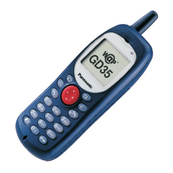
Panasonic EB-GD35 Service Manual
Gsm personal cellular phone
Hide thumbs
Also See for EB-GD35:
- Operating instructions manual (70 pages) ,
- Operating instructions manual (70 pages)
Table of Contents
Advertisement
Quick Links
This service information is designed for experienced repair technicians only and is not designed for use by the general public. It does not contain
warnings or cautions to advise non-technical individuals of potential dangers in attempting to service a product.
Products powered by electricity should be serviced or repaired only by experienced professional technicians. Any attempt to service or repair the
product or products dealt with in this service manual by anyone else could result in serious injury or death.
http://cxema.ru
EB-GD35
EB-GD35C
Frequency Range
Tx/Rx frequency
separation
RF Channel Bandwidth
Number of RF channels
Speech coding
Operating temperature
Type
RF Output Power
Modulation
Connection
Voice digitizing
Transmission speed
Diversity
Signal Reception
Intermediate Frequency
Antenna Terminal
Impedance
Antenna VSWR
Dimensions
Volume
Weight
Display
Illumination
Keys
SIM
External DC Supply
Voltage
Battery
Standby Battery Life
Conversation Battery Life 360 minutes maximum
Battery life figures are dependent on battery and network conditions, SIM card and usage.
WARNING
© 2001 Matsushita Communication Industrial UK Ltd.
All rights reserved. Unauthorized copying and
distribution is a violation of law.
Order Number: MCUK010301C8
Personal Cellular Phone
900 MHz
Tx: 890 - 915MHz
Tx: 1710 -1785 MHz
Rx: 935 - 960 MHz
Rx: 1805 -1880 MHz
45 MHz
95 MHz
200 kHz
124
374
Full rate/Half rate/Enhanced Full rate
-10 °C to +55 °C
Class 4 Handheld
Class 1 Handheld
2 W maximum
1 W maximum
GMSK (BT = 0.3)
8 ch / TDMA
13 kbps RPE-LTP / 13 kps ACLEP / 5.6 kps CELP / VSLEP
270.3 kbps
Frequency hopping
Double superheterodyne
360 MHz
50 Ω
< 2.1 : 1
Height: 120.5 mm excluding antenna
Width:
46 mm
Depth:
20.5 mm
100 ml
109 g
Graphical chip on glass liquid crystal, Alphanumeric,
16 characters x 3 rows + 2 lines of icons.
4 LEDs for the LCD
8 LEDs for the keypad (Green)
1 LED Incoming call (Green)
1 Charging LED (Red)
18-key Keypad, Navigation key.
Plug-in type only
5.8 V
3.6 V nominal, 700mAh, Ni-MH
175 hrs maximum
1800 MHz
Advertisement
Table of Contents

Related Manuals for Panasonic EB-GD35


Summary of Contents for Panasonic EB-GD35
- Page 1 Order Number: MCUK010301C8 Personal Cellular Phone EB-GD35 EB-GD35C 900 MHz 1800 MHz Frequency Range Tx: 890 - 915MHz Tx: 1710 -1785 MHz Rx: 935 - 960 MHz Rx: 1805 -1880 MHz Tx/Rx frequency 45 MHz 95 MHz separation RF Channel Bandwidth...
-
Page 2: Table Of Contents
EB-GD35 EB-GD35C Every care has been taken to ensure that the contents of this manual give an accurate representation of the equipment. However, Matsushita Communication Industrial UK Ltd. accepts no responsibility for inaccuracies which may occur and reserves the right to make changes to the specification or design without prior notice. -
Page 3: Introduction
They must not be incinerated, or disposed of as ordinary rubbish. 1.1. Purpose of the Manual This Service Manual contains the information and procedures required for installing, operating and servicing the Panasonic GSM Personal Cellular Mobile Telephone system operating on the GSM Digital Cellular Network. -
Page 4: General Description
2.2. Features Panasonic Telephone Models GD35 and GD35C are high performance, small, light, handsets for business and domestic use. The following features are provided: Triple Rate, which includes Full Rate, Half rate and Enhanced Full Rate (EFR) speech, codec. -
Page 5: Operating Instructions
EB-GD35 EB-GD35C 3 OPERATING INSTRUCTIONS 3.1. General This section provides a brief guide to the operation and facilities available on the telephone handset. Refer to the Operating Instructions supplied with the telephone for full operational information. 3.2. Liquid Crystal Display The telephone handset has a graphical chip on glass display. -
Page 6: Location Of Controls
EB-GD35 EB-GD35C 3.3. Location of Controls Incoming / Charge indicator: Green - Incoming call. Red - Charging battery pack. External connector: Used to connect to external accessories or to charging equipment. Antenna Earpiece Display External Power Microphone Personal Handsfree Connector... -
Page 7: Concept Of Operation
EB-GD35 EB-GD35C 3.4. Concept of Operation There is a close relationship between the Select keys, Navigation key and display. Secondary Main Option Area Option Area Select Key Select Key Navigation 10405-1 Figure 3.3: Concept of Operation Pressing up and down ( ) will move the pointer up and down and scroll through more information in the main area of the display. -
Page 8: Incoming Call Line Modification (Cli)
EB-GD35 EB-GD35C 3.6. Incoming Call Line Identification (CLI) When a call is received the last 6 digits of the CLI information is matched with the phonebook. Therefore an incoming call could match to the wrong phonebook entry. 3.7. Hot Key Dial Source List The source for Hot Key Dial Numbers is normally ‘Phonebook’... -
Page 9: Public Man Machine Interface (Mmi)
EB-GD35 EB-GD35C 3.9. Public Man Machine Interface (MMI) 3.9.1 General It is possible to operate all GSM telephones in the same way using the Public MMI. The following operations will work with all GSM telephones. However, this information is restricted to those operations supported by the telephone. -
Page 10: Calling Line Identification
EB-GD35 EB-GD35C 3.9.7 Calling Line Identification Feature Service Code Calling Line Identification Presentation (CLIP) Calling Line Identification Restriction (CLIR) Connected Line Presentation (CLOP) Connected Line Restriction (CLOR) Enable * <SERVICE CODE> * # <SND> Disable # <SERVICE CODE> * # <SND>... -
Page 11: Call Divert
EB-GD35 EB-GD35C 3.9.9 Call Divert Call Divert Type Service Code Divert all calls Divert all calls if busy Divert calls if no reply Divert if not reachable Set (except “No Reply” Call * * <SERVICE CODE> * <FORWARD TELEPHONE NUMBER> * <TELECOMMUNICATION SERVICE>... -
Page 12: Troubleshooting
EB-GD35 EB-GD35C 3.10. Troubleshooting The user is given the following information and advised to contact the dealer if the problems persist: Problem Cause Remedy Telephone will not switch Check that the battery pack is fully charged and correctly connected to the telephone. -
Page 13: Important Error Messages
EB-GD35 EB-GD35C 3.11. Important Error Messages The following table is a list of error messages that may occur during use of the telephone, with a description and suggested course of action: Error Message Explanation / Remedy Area not Allowed Roaming in the selected area is not allowed. -
Page 14: Sim Personalisation
EB-GD35 EB-GD35C 3.13. SIM Personalisation 3.13.1 Introduction SIM personalisation will limit the use of the telephone to a single SIM, a SIM supplied by one Network/Sub-network/Service Provider or a SIM purchased by a company (corporation). If a personalised handset contains a SIM that is from a different source, it will display the message “SIM ERROR”... -
Page 15: Gsm Services Supported By Pc Card
EB-GD35 EB-GD35C 3.13.5 Enabling Procedure to point at: Network “SIM” for SIM Personalisation ”Network” for Network Personalisation Sub-Network “Subnetwork” for Subnetwork Personalisation Service (SP) ”SP” for Service Provider Personalisation or ”Corporate” for Company Personalisation. the 16 digit Control Key. the 16 digit Control Key. -
Page 16: Gsm Network Codes And Names
EB-GD35 EB-GD35C 3.15. GSM Network Codes and Names Access Network Country Service or Operator Phone Display Band Code Code ALBANIA +355 AMC MOBIL AMC - AL GSM 900 ANDORRA +376 MOBILAND STA-MOBILAND GSM 900 ARMENIA +374 ARMGSM RA-ARMGSM GSM 900... - Page 17 EB-GD35 EB-GD35C Access Network Country Service or Operator Phone Display Band Code Code HONG_KONG +852 HK SMC HK SMC GSM 900 HK TELECOM CAMPERSANDW HKT GSM 900 NEW WORLD NEW WORLD GSM 1800 Orange Orange GSM 900 P Plus P Plus...
- Page 18 EB-GD35 EB-GD35C Access Network Country Service or Operator Phone Display Band Code Code NAMIBIA +264 NAM MTC GSM 900 NETHERLANDS Ben NL Ben NL GSM 1800 KPN TELECOM NL KPN TELECOM GSM 900 LIBERTEL NL LIBERTEL GSM 900 NL Dutchtone...
- Page 19 EB-GD35 EB-GD35C Access Network Country Service or Operator Phone Display Band Code Code TAIWAN +886 Chunghwa Chunghwa GSM 900 Far EasTone Far EasTone GSM 900 KGT-ONLINE KGT-ONLINE GSM 1800 ROC MOBITAI MOBITAI GSM 900 TUNTEX TUNTEX GSM 1800 TWN GSM...
-
Page 20: Glossary Of Terms
EB-GD35 EB-GD35C 3.16. Glossary of Terms Term Definition DTMF Dual Tone Multiple Frequency tones. The numeric keys 0 to 9, and * and # will generate different DTMF tones when pressed during conversation. These are used to access voice mail, paging and home banking services. -
Page 21: Disassembly / Reassembly Instructions
EB-GD35 EB-GD35C 4 DISASSEMBLY / REASSEMBLY INSTRUCTIONS General 4.1. This section provides disassembly and reassembly procedures for the main components of the telephone. These assemblies MUST be performed by qualified service personnel at an authorised service centre. The following Warnings and Cautions MUST be observed during all disassembly / reassembly operations: WARNING The equipment described in this manual contains polarised capacitors utilising liquid electrolyte. - Page 22 EB-GD35 EB-GD35C Slide the battery lock to the ‘release’ position, and lift the battery from the case. 10383-1 Figure 4.2: Battery Removal Remove the four case screws located inside the battery compartment. 10384-1 Figure 4.3: Case Screw Removal Remove the cover from the case by pulling from the connector end of the telephone. Care must be taken when separating the case from the cover as the retaining clips may be very stiff - if necessary, re-attach the battery cover to provide extra support for the case.
- Page 23 EB-GD35 EB-GD35C Remove the two screws securing the PCB assembly to the case back. The PCB may now be removed from the case. 10385-1 Figure 4.5: PCB Assembly Removal 4.2.2 LCD Removal Gently prise apart the two ears of the LCD Retainer so that it is released from the PCB.
- Page 24 EB-GD35 EB-GD35C 4.2.3 Case-Mounted Components Remove the keypad membrane by peeling it away from the case front. 10389-1 Figure 4.8: Keypad Membrane Removal Remove the microphone assembly by prising upward with a small screwdriver blade or similar blunt object through the slot in the side of the microphone holder.
-
Page 25: Reassembly
EB-GD35 EB-GD35C Using a small screwdriver blade or similar blunt object, depress the lug on the antenna base in order to release the entire antenna unit. 10393-1 Figure 4.12: Antenna Removal Lift out the SIM connector from the case by gripping by hand or with a pair of small pliers. -
Page 26: Technical Specifications
EB-GD35 EB-GD35C 5 TECHNICAL SPECIFICATIONS 5.1. Tx Characteristics All data is applicable to GSM 900 and GSM 1800 except where stated. 5.1.1. Frequency Error ±0.1 ppm max., relative to base station frequency. 5.1.2. Modulation Phase Error RMS: Equal to or less than 5 °... -
Page 27: Rx Characteristics
EB-GD35 EB-GD35C 5.1.6. Output Level, Dynamic Operation GSM 900 Tolerance for Conditions (dB) Power Control Transmitter Output Power Level (dBm) Normal Extreme GSM 1800 Tolerance for Conditions (dB) Power Control Transmitter Output Power Level (dBm) Normal Extreme 5.1.7. Residual Peak Power Equal to or less than 70 dBc (BW = 300 kHz) 5.2. - Page 28 EB-GD35 EB-GD35C GSM 1800 Full Rate Speech The reference sensitivity performance in terms of frame erasure, bit error, or residual bit error rates (whichever is appropriate) is specified in the following table, according to the propagation conditions. Propogation Conditions Propogation Conditions...
- Page 29 EB-GD35 EB-GD35C Blocking: Small MS level in dBµVemf() Frequency GSM 900 GSM 1800 FR ±600 kHz to FR ±800 kHz FR ±800 kHz to FR ±1.6 MHz FR ±1.6 MHz to FR ±3 MHz 915 MHz to FR -3 MHz FR ±3 MHz to FR 980 MHz...
-
Page 30: Test And Measurement
EB-GD35 EB-GD35C 6 TEST AND MEASUREMENT 6.1. Introduction This section provides information on testing the telephone. The layout is as follows Section 6.2 External testing: describes equipment requirements and general set up procedure. Section 6.3 Complete Unit Test Setup: describes how the items of test equipment are used together and general set up procedure. - Page 31 EB-GD35 EB-GD35C PCB Repair Jig (Part No. JT00061) This unit provides the necessary connections between the handset PCB and external test equipment. The RF probe can be ordered separately as Part No. JT00060. DATA RF CABLE CLAMP DC POWER RF PROBE...
-
Page 32: Complete Unit Setup
EB-GD35 EB-GD35C 6.3. Complete Unit Setup +12V POWER INTERFACE SUPPLY UNIT RS232 GSM TESTER RF CABLE POWER SUPPLY PCB REPAIR JIG 10417-1 Figure 6.4: Complete Unit Test Setup External Testing Setup Procedure IMPORTANT NOTE To allow accurate measurement of the complete unit the test equipment must be connected as shown. The PCB Test Setup must be used to enable repair to PCBs. - Page 33 EB-GD35 EB-GD35C Power On into Test Mode Connect the test equipment as shown in Section 6.3. Ensure that the following settings are made: a) Interface box IFB003 or IFB004 Power: DOWN postion IGN: UP position Ext Pwr: UP position Voltage: Top position (4.8 V)
- Page 34 EB-GD35 EB-GD35C Channel Box software loaded and the screen indication as follows PC Screen (SCRN9) On the PC, select NORMAL MODE and press ENTER. Press Shift F10 on the PC. After approximately 1 second, set the ExtPwr switch to ON until the unit powers up.
-
Page 35: Channel Box Test Commands
EB-GD35 EB-GD35C 6.4. Channel Box Test Commands The following table outlines the commands available using the channel box software. After the telephone unit has been switched on (Section 6.4), use the up / down cursor keys on the PC keyboard to select the channel box command. -
Page 36: Adjustment Mode
EB-GD35 EB-GD35C 6.5. Adjustment Mode 6.5.1 RF Calibration Procedure NOTE: See Section 6.2 for a list of the equipment and setup procedures required to perform the following adjustment and calibration procedures. The following procedures MUST be performed after replacement or repair of the PCB. Failure to do so may result in incorrect operation of the telephone. - Page 37 EB-GD35 EB-GD35C 6.5.2 Ramping Gain The carrier power must be measured and calibrated for each power level at channel 62. GSM 900 Output Power (dBm) Power Level Target Spec Change / dB (PL) Nominal 32.3 32.0 32.6 31.8 32.8 30.9 30.4...
- Page 38 Calibration of output power on each power level NOTE: To ensure that the telephone operates within set SAR margins, Panasonic recommends that a power meter capable of measurement to an accuracy of ±0.2 dB is used when calibrating power levels. Use of a less accurate power meter may result in the telephone failing to meet SAR standards.
- Page 39 EB-GD35 EB-GD35C Select VIEW TRIM PL MCH, and make a note of this value. Figure 6.10: Power level view 2 Perform the following calculation and make a note of the result: New Trim Value = Old Trim Value + (Required Power - Measured Power) x Change per dB...
- Page 40 EB-GD35 EB-GD35C 11. Select PROGRAM TRIM PL MCH GSM. Figure 6.12: Power level selection 2 12. Highlight the PL14 field and press ENTER. Figure 6.13: Power level selection 3 13. Enter the value calculated in step 9 into the data field and then press ENTER.
- Page 41 EB-GD35 EB-GD35C 18. After calibrating at channel 62, the carrier power must be measured and calibrated at LOW and HIGH channels as shown in the table below. Channel GSM 900 GSM 1800 Bottom (624) High (774) 19. Repeat steps 2 to 14 for the GSM 1800 settings in the following order: PL10 (limits ±0.5 dB).
- Page 42 EB-GD35 EB-GD35C If the measured power is not -90 ±1, then make the following calculation: RSSI offset value = [-(90 + MEASURED RSSI VALUE)] x 2 = [ -90 - MEASURED RSSI VALUE] x 2, for example [-(90 + (95))] x 2...
- Page 43 EB-GD35 EB-GD35C 10. Press ESC. 11. Select TRIM RSSI and press ENTER. Figure 6.17: RSSI reading 3 12. Highlight RSSI Mch GSM and press ENTER. Figure 6.18: RSSI Reading 4 http://cxema.ru...
- Page 44 EB-GD35 EB-GD35C 13. Make the following calculation: RSSI Offset Value (step 8) + reading noted in step 6. Enter the result in to the RSSI Mch field. 14. Press ENTER. 15. Press ESC. 16. Measure the RSSI level again by highlighting the RSSI dBm field again and press ENTER.
- Page 45 EB-GD35 EB-GD35C 6.5.4 Battery Calibration Preliminaries There are two procedures associated with battery calibration: Battery Temperature. Battery Voltage Calibration. A dummy battery (Part No. JT00059) is required to perform these checks Connect the dummy battery to phone as shown below.
- Page 46 EB-GD35 EB-GD35C Scroll down to TEMP BIAS. Select 20µA and press ENTER. Figure 6.22: Battery temperature calibration 2 Press F4 and select View ADC Lines. Figure 6.23: Battery temperature calibration 3 http://cxema.ru...
- Page 47 EB-GD35 EB-GD35C Check the value for ADIN2 (Bat Temp). If the value is outside the range 27 - 60 then there is a fault and further investigation is required. Otherwise, subtract this value from the theoretical value of 41 and record the result for later use.
- Page 48 EB-GD35 EB-GD35C 11. Scroll down to, and select BAT TEMP. Figure 6.26: Battery temperature calibration 6 12. Enter the value recorded in step 8. Figure 6.27: Battery temperature calibration 7 Battery temperature offset is now calibrated all that remains is to check the circuitry is working by testing the minimum temperature extreme to verify the offset readings are within acceptable limits.
- Page 49 EB-GD35 EB-GD35C Set the power supply voltage output to exactly 4.2 V. Ensure the resistor selection switch is in the OFF position. Enter Test Set Mode on the channel box. Power-up the phone, press Shift F10. Scroll to CONTROL OUT, select BVOLT and press ENTER.
- Page 50 EB-GD35 EB-GD35C Check and record the value for VBAT:BAT VOLT. Note this is for VBAT high. If the value is outside the range 564 - 664 then a fault is present and further investigation is required. Figure 6.30: High voltage calibration 3 To calibrate, press F6.
- Page 51 EB-GD35 EB-GD35C Highlight BAT VOLT HIGH and press ENTER to select. Figure 6.32: High voltage calibration 5 Enter the value recorded in step 6. Figure 6.33: High voltage calibration 6 Battery Low Voltage Calibration Set the power supply voltage to exactly 3.2 V.
- Page 52 EB-GD35 EB-GD35C Repeat steps 3 - 5 for high voltage calibration procedure. Check and record the value for VBAT:BAT LOW. Note this is for VBAT low. If the value is outside the range 468 ±50 then a fault is present and further investigation is required.
- Page 53 EB-GD35 EB-GD35C Select BAT VOLT LOW and press ENTER. Figure 6.36: Low voltage calibration 3 Enter the value recorded in step 2. The message SAVING EV TRIM DATA will be displayed, indicating that Battery voltage calibration has been completed. http://cxema.ru...
-
Page 54: Replacement Parts List
EB-GD35 EB-GD35C 7 REPLACEMENT PARTS LIST 7.1. Exploded Diagram M107 M109 M108 M102 M104 M109a M101 M106 M103 10381-1 Figure 7.1: Exploded Diagram 7.2. Case and Cover Parts Ref. Part Number Description Ref. Part Number Description RE76006A RECEIVER (SPEAKER) M103 See Section 7.2... -
Page 55: Lcd Variants
EB-GD35 EB-GD35C 7.3. LCD Panel Variants Ref. No. Part No. Part Name & Description GD35BRD041 GD35 PCB ASSEMBLY BEN GD35BRD042 GD35 PCB ASSEMBLY DIAX Ref. Part Number Description GD35BRD043 GD35 PCB ASSEMBLY DIXONS GD35BRD044 GD35 PCB ASSEMBLY PBSUK M103 2EA615AAAA... - Page 56 EB-GD35 EB-GD35C Ref. No. Part No. Part Name & Description Grid Ref. No. Part No. Part Name & Description Grid C064 ECJ0EC1H100D CAP CER 10pF +/-0.5pF 50V NP0 C242 ECJ0EC1H470J CAP CER 47pF 5% 50V NP0 C065 ECJ0EC1H330J CAP CER 33pF 5% 50V NP0...
- Page 57 EB-GD35 EB-GD35C Ref. No. Part No. Part Name & Description Grid Ref. No. Part No. Part Name & Description Grid DS07 B3ABB0000035 DIODE LED GREEN 2.2V 20mA R019 ERJ6RSFR15V RES 0.15 OHM 1% 1/10W 012 DS08 B3ABB0000035 DIODE LED GREEN 2.2V 20mA...
-
Page 58: Document Packs
EB-GD35 EB-GD35C 7.8. Document Packs Ref. No. Part No. Part Name & Description Grid R351 ERJ2GEJ104X RES 100K OHM 5% 1/16W 05 R352 ERJ2GEJ472X RES 4.7K OHM 5% 1/16W 05 Ref. No. Part No. Part Name & Description R353 ERJ2GE0R00X... -
Page 59: Circuit Diagrams
EB-GD35 EB-GD35C 8 CIRCUIT DIAGRAMS Figure 8.3 Figure 8.2 Figure 8.1: GD35 Top Level Schematic http://cxema.ru... - Page 60 EB-GD35 EB-GD35C Figure 8.4 Figure 8.5 Figure 8.2: Baseband Top Level...
- Page 61 EB-GD35 EB-GD35C Figure 8.6 Figure 8.7 Figure 8.3: RF Top Level...
- Page 62 EB-GD35 EB-GD35C Figure 8.4: Baseband: Peripherals...
- Page 63 EB-GD35 EB-GD35C GD35C only Figure 8.5: Baseband: Processor...
- Page 64 EB-GD35 EB-GD35C Figure 8.6: RF Front End...
- Page 65 EB-GD35 EB-GD35C Figure 8.7: RF IF and Synthesiser...
-
Page 66: Layout Diagrams
EB-GD35 EB-GD35C 9 LAYOUT DIAGRAM Figure 9.1: PCB Layout Diagram...