Table of Contents
Advertisement
Quick Links
Download this manual
See also:
User Manual
Advertisement
Table of Contents

Related Manuals for Draytek VigorTalk ATA 24SH


Summary of Contents for Draytek VigorTalk ATA 24SH
-
Page 2: Installation Guide
ATA-24 SH Installation Guide Installation Guide Version: 1.0 Date: 30/07/2009 ATA-24 SH Installation Guide... -
Page 3: Copyright Information
Copyright Information Copyright Copyright 2009 All rights reserved. This publication contains information that is Declarations protected by copyright. No part may be reproduced, transmitted, transcribed, stored in a retrieval system, or translated into any language without written permission from the copyright holders. Trademarks The following trademarks are used in this document: Microsoft is a registered trademark of Microsoft Corp. -
Page 4: Regulatory Information
Regulatory Information Federal Communication Commission Interference Statement This equipment has been tested and found to comply with the limits for a Class A digital device, pursuant to Part 15 of the FCC Rules. These limits are designed to provide reasonable protection against harmful interference in a residential installation. -
Page 5: Customer Support
Warranty We warrant to the original end user (purchaser) that this device will be free from any defects in workmanship or materials for a period of two (2) years from the date of purchase from the dealer. Please keep your purchase receipt in a safe place as it serves as proof of date of purchase. During the warranty period, and upon proof of purchase, should the product have indications of failure due to faulty workmanship and/or materials, we will, at our discretion, repair or replace the defective products or components, without charge for either parts or labor, to whatever extent we deem necessary tore-store the... -
Page 6: Table Of Contents
1. Introduction......................1 1.1 Features of VigorTalk ATA24 SH ....................1 1.1.1 General Features ......................1 1.1.2 VoIP Features ....................... 2 1.1.3 Line Test and Diagnostic Functions................2 1.2 Applications ..........................3 1.2.1 Branch Office Interconnection..................3 1.2.2 Security ......................... 3 2. -
Page 7: Introduction
VigorTalk ATA-24 SH could provide large VoIP ports which is designed for ISP/SI. It not only provides high quality call service, but also supports various VoIP protocol and supplementary services. Moreover, it combines guaranteed bandwidth, remote management and administrative functions to meet increasing demands for higher reliability in today's broadband environment. -
Page 8: Voip Features
VoIP Service - VigorTalk ATA24 SH can provide toll quality voice communication in terms of voice quality and reliability for the users. FXS (24-port) MGCP/SIP/H248 Codec G.711, 729A, 723.1, G.726 VAD (Silence Suppression) & CNG G.168-2000 Echo Canceller, Jitter Buffer Packet Loss Concealment RFC2833-Out of Band DTMF Gain/Attenuation Setting... -
Page 9: Applications
VigorTalk ATA-24 SH can extend internal ports to reduce operational fee of the company or business. VigorTalk ATA-24 SH provides 24 FXS interfaces which can support VoIP service between branch offices by bundled with a security router and an IP-PBX server. The DoS function helps to detect and mitigate DoS attacks. - Page 10 ATA-24 SH Installation Guide...
-
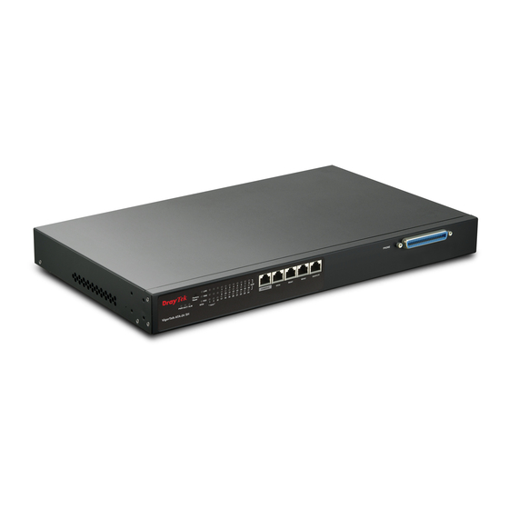
Page 11: Panel Explanation
This chapter will introduce the LED indicators and connectors for preparing the installation listed in Chapter 3. All connections are made on the front panel of the VigorTalk ATA24 SH except power connector. Interface Description Factory Reset Used to restore the default settings. Turn on the adapter (VACT LED is blinking). -
Page 12: Led Indication
RJ-21 Cable for RJ-21 to RJ-21 or CPP Panel or telephone PHONE RJ-21 to RJ-11 Status Explanation The adapter is powered on. The adapter is powered off. VACT On/Blinkin The system is active. The system is hanged. The system alarm is active. The Ethernet link is established. - Page 13 Status Explanation It means a full duplex connection on corresponding port. It means a half duplex connection on corresponding port. VoIP (1-24) The phone is off hook (the handset of phone is hanging). Blinking A phone call is incoming or on-line. ATA-24 SH Installation Guide...
- Page 14 ATA-24 SH Installation Guide...
-
Page 15: Installation And Connection
VigorTalk ATA24 SH can be installed on 19-, 23-inches racks by using standard brackets in 19-inch rack or optional larger brackets on 23-inch rack with other equipments. The bracket for 19-, 23-inch racks are shown below. Attach the brackets to the chassis in 19-, 23-inch rack. The second bracket attaches the other side of the chassis as above procedure. -
Page 16: Frame Ground Installation
same time it can decrease unnecessarily rubbing on the desk. Therefore, you can simply put the device on your desk or any flat surface without worrying damage. The frame ground is on the rear side of the VigorTalk ATA24 SH which is powered by AC connector. -
Page 17: Power Connection
Phone service is available in VigorTalk ATA24 SH. You can connect a RJ-11 jack port attached in a CPP to a telephone directly. The following example shows the connection for Voice transmission through CPP. Before you purchasing the device, please check your environment to determine which power type that matches with your requirement. -
Page 18: Console Port Connection
The default setting of the console port is “baud rate 115200, no parity, and 8 bit with 1 stop bit (N81)”. For the initial configuration, users need to use terminal emulator software on a computer and connect it to a network module through the console port. Users can connect the RJ-45 end of the console cable to the console port of the network module. -
Page 19: Management Port Connection
Users can connect the RJ-45 cable to the MGN port of the device. The IP address is 192.168.1.1 by default. The subnet of PC should be the same as default IP setting. ATA24-SH> network/mgn> ip -s -------------------------------------------------------------------------------- MGN IP Status -------------------------------------------------------------------------------- IP Address : 192.168.1.1... - Page 20 ATA24-SH/network/wan> static -s 1 -------------------------------------------------------------------------------- WAN1 Static Setting -------------------------------------------------------------------------------- IP Address: 172.16.1.2 Subnet Mask: 255.255.255.0 Default Gateway: 172.16.1.1 Primary DNS: 168.95.1.1 Secondary DNS: 168.95.1.2 ATA-24 SH Installation Guide...
-
Page 21: Appendix: Connectors
Connections made with two 50-pin champ cables are attached to the RJ21 interface on VigorTalk ATA24 SH. Each cable terminates with a 50-pin Telco straight champ connector. Pin 1 Pin25 Pin 26 Male Pin 50 Pin assignments between the Line and the PSTN splitter. Wire Color TIP/RING Port Wire Color... -
Page 22: Standard 10/100 Base-T Ethernet Interface Connector
VigorTalk ATA24 SH during the preliminary installation. The “management cable”, as shown in Figure 1-15, converts the RJ45 to the RS232 interface. The RJ45 jet connects to a console interface in the VigorTalk ATA24 SH, while the RS232 DB9 connecting to a console port on the computer. -
Page 23: Standard 10/100/1000 Base-T Ethernet Interface Connector
RJ45 jets provide 8P8C 10/100/1000 Base-T Ethernet interfaces. The interface supports MDI/MDIX auto-detection of either straight or crossover RJ45 cables. These cables are used on GE interfaces for subtending connection on Master and UP1, UP2/MGN port on Slave. RJ-45 Straight-through Cable Pin-outs (8P8C) RJ-45 Crossover Cable Pin-outs (8P8C) Signal Signal...