Motorola BSR 2000 Installation Manual
Broadband services router
Hide thumbs
Also See for BSR 2000:
- Reference manual (64 pages) ,
- Configuration and management manual (650 pages)
Table of Contents
Advertisement
Quick Links
Download this manual
See also:
Reference Manual
Advertisement
Table of Contents

Related Manuals for Motorola BSR 2000


Summary of Contents for Motorola BSR 2000
- Page 1 BSR 2000 Installation Guide 526359-001 Release 1.0 MGBI...
- Page 2 (such as translation, transformation or adaptation) without written permission from Motorola, Inc. Motorola reserves the right to revise this publication and to make changes in content from time to time without obligation on the part of Motorola to provide notification of such revision or change. Motorola provides this guide without warranty of any kind, either implied or expressed, including, but not limited to, the implied warranties of merchantability and fitness for a particular purpose.
- Page 3 Caring for the Environment by Recycling When you see this symbol on a Motorola product, do not dispose of the product with residential or commercial waste. Recycling your Motorola Equipment Please do not dispose of this product with your residential or commercial waste. Some countries or regions, such as the European Union, have set up systems to collect and recycle electrical and electronic waste items.
- Page 4 Motorola Kundeservice. Milieubewust recycleren Als u dit symbool op een Motorola-product ziet, gooi het dan niet bij het huishoudelijk afval of het bedrijfsafval. Uw Motorola-materiaal recycleren. Gooi dit product niet bij het huishoudelijk afval het of bedrijfsafval. In sommige landen of regio's zoals de Eu- ropese Unie, zijn er bepaalde systemen om elektrische of elektronische afvalproducten in te zamelen en te recycleren.
- Page 5 Motorolas kundtjänst för hjälp. Újrahasznosítással a környezet védelméért Ha ezt a jelzést látja egy Motorola terméken, ne dobja ki azt lakossági vagy ipari hulladékba. Motorola termékének újrahasznosítása Kérjük ne dobja ki ezt a terméket lakossági vagy ipari hulladékba. Egyes országok ill. régiók, mint az Európai Unió...
- Page 6 Motorola Motorola Motorola Motorola Motorola Motorola Motorola Motorola Motorola...
-
Page 7: Regulatory Compliance
Regulatory Compliance CAUTION RISK OF ELECTRIC SHOCK CAUTION: TO REDUCE THE RISK OF ELECTRIC SHOCK, DO NOT REMOVE COVER (OR BACK). NO USER-SERVICEABLE PARTS INSIDE. REFER SERVICING TO QUALIFIED SERVICE PERSONNEL. These servicing instructions are for use by qualified personnel only. To reduce the risk of electrical shock, do not perform any servicing other than that contained in the Installation and Troubleshooting Instructions unless you are qualified to do so. - Page 8 This equipment operates over the marked Voltage and Frequency range without requiring manual setting of any selector switches. Different types of line cord sets may be used for connections to the mains supply circuit and should comply with the electrical code requirements of the country of use.
-
Page 9: Fcc Compliance
FCC Declaration of Conformity According to 47 CFR, Parts 2 and 15 for radio frequency devices, Motorola, Inc. 111 Locke Drive, Marlborough, MA 01752 declares under sole responsibility that the product identifies with 47 CFR Part 2 and 15 of the FCC Rules as a Class B digital device. -
Page 10: Laser Safety
Canada. Laser Safety All Motorola, Inc. systems equipped with laser products are Class 1 Laser Products in compliance with IEC 60825 and CDRH 21 CFR 1040.10 and 1040.11 CAUTION: Use of controls or adjustments or performance of procedures other than those specified herein may result... -
Page 11: Vcci Statement
VCCI Statement Korean MIC Statement Russian GOST Safety Standards and Emissions Standards The BSR 2000 is designed to meet GR-1089-CORE:1999 and complies with the following specifications. Safety • UL 60950-1 1st Edition:2003 • CSA 22.2 No 60950-1-03 1st Edition:2003 •... - Page 12 Korean MIC Notice 2005-82: 2005 Class B Immunity • EN 300 386 V1.3.1:2001 • EN 55024:2003 • CISPR 24:2002 • Korean MIC Notice 2005-83:2005 Environmental The BSR 2000 is designed to meet the following specifications. • EN 300 019 • EN 300 119 • GR-63-CORE: 1995...
-
Page 13: Table Of Contents
Required Tools and Equipment ..................2-2 Inspecting the Installation Site ....................2-3 Site Installation Options ......................2-3 Equipment Rack Choices ....................2-3 Mounting the BSR 2000 in an Equipment Rack .................2-4 Rack Mounting Options ....................2-4 Before You Begin ......................2-4 Rack-Mounting Procedure....................2-4 Marking the Installation Location on the Equipment Rack .......2-4 Attaching the Mounting Brackets ..............2-4... - Page 14 Connecting Network Cables......................2-8 Connecting an Ethernet Cable to the BSR 2000 ..............2-9 Connecting a Cable to the Redundant Ethernet Port on the BSR 2000......2-10 Connecting Gigabit Ethernet Cables to the BSR 2000...........2-11 Connecting a Cable to the T1/E1 BITS Interface............2-13 Connecting Coaxial Cables to the BSR 2000..............2-14...
- Page 15 Specifications Overview ............................A-1 Physical ............................A-1 Electrical.............................A-2 Environmental ..........................A-2 Network Interfaces ........................A-2 SFP Module Specifications ......................A-2 RF Spectrum..........................A-4 Timing Generation ........................A-4 Connector Pinouts Overview ............................ B-1 Console Port Connector ......................B-1 10/100 Ethernet Port Connectors ....................B-3 Gigabit Ethernet Port Connector ....................B-4 T1/E1 BITS Connector.......................
- Page 16 BSR 2000 Installation Guide Jewelry Removal Caution....................C-4 Safety Guidelines ........................C-5 Electrical Safety Guidelines .................... C-6 In Case of Electrical Accident ................C-6 Index MGBI 526359-001...
-
Page 17: Preface
2000 (BSR 2000™). Audience This document is for use by those persons who will install and configure the BSR 2000™ product. Only trained service personnel should install, maintain, or replace the BSR 2000. Documentation Set The following documents comprise the BSR 2000 documentation set: BSR 2000 Installation Guide This document describes how to install the BSR 2000 product. -
Page 18: Conventions
BSR 2000 Installation Guide BSR 2000 SNMP MIB Reference Guide This document describes the Simple Network Management Protocol (SNMP) MIBs; provides information that describes standard and proprietary MIB support; describes how to walk the MIBs and how to compile and load the SNMP MIBs. It also provides task examples. -
Page 19: Notes, Cautions, Warnings
Preface Convention Example Explanation italic text boot system <filename> Italic type indicates variables for which you supply values in command syntax descriptions. It also indicates file names, directory names, document titles, or emphasized text. This font indicates system output. screen display Wed May 6 17:01:03 2000 vertical bar |... -
Page 20: Contacting Support
Technical Response Center (TRC): U.S. 1-888-944-HELP 1-888-944-4357 International +.215-323-0044 http://broadband.motorola.com/noflash/websupport.html The TRC is on call 24 hours a day, 7 days a week. In addition, Motorola Online offers a searchable solutions database, technical documentation, and low-priority issue creation and tracking. xviii MGBI 000000-000... -
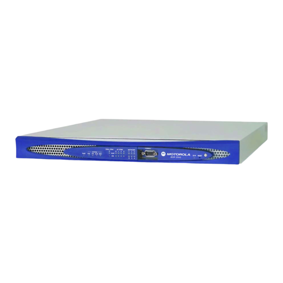
Page 21: Bsr 2000 Product Description
1U height stackable enclosure. The BSR 2000 complements the higher-capacity, carrier-class BSR 64000. The BSR 2000 is designed for smaller distribution hubs or larger sites in the early stages of providing expanded broadband services where the BSR 64000 is not required. -
Page 22: Front View
Bits 10/100 Power Status Wireless T1/E1 BITS Upstream ports Ethernet connector connector (Type F connector) AC power Power ports Downstream port receptacle switch Redundant GIG-E (Type F connector) 10/100 port SFP ports bsr2k019 Figure 1-1 The BSR 2000 MGBI 526359-001... -
Page 23: Performing Installation Tasks
This chapter provides information about the following topics. Preinstallation Tasks Inspecting the Installation Site Site Installation Options Mounting the BSR 2000 in an Equipment Rack Setting up the BSR 2000 for Desktop Operation Connecting Network Cables Setting up a Console Monitor... -
Page 24: Preinstallation Tasks
Confirming that you have the accessories to perform the installation procedures. Obtaining the items you need to complete the installation procedures. Installation Accessories In addition to this document and the product release notes, the BSR 2000™ shipment includes the following items: Two rack-mounting brackets Eight flathead #10-32 x 7/16 Phillips screws One 8-ft. -
Page 25: Inspecting The Installation Site
Inspecting the Installation Site Inspect the BSR 2000 installation site to ensure the following: At least 3 in. (7.5 cm) clearance exists on the sides of the BSR 2000 to allow for adequate airflow for component cooling. At least 3 ft. (1 m) exists at the front and rear panels to connect the Ethernet cables, upstream and downstream cables, wireless cable, RS-232 Console Monitor cable, and power cord. -
Page 26: Mounting The Bsr 2000 In An Equipment Rack
To mount the BSR 2000 in an equipment rack, perform the following tasks: 1. Mark the location on the rack where you intend to mount the BSR 2000 2. Attach the mounting brackets to the sides of the BSR 2000 chassis. - Page 27 1. Match and align the mounting bracket holes with the threaded holes at the position for the mounting option you selected. Be sure to use the left bracket on the left side of the BSR 2000 and the right bracket on the right side of the BSR 2000.
-
Page 28: Mounting And Securing The Bsr 2000 In An Equipment Rack
One person should hold the BSR 2000 in position while the other secures it in the equipment rack. 1. Lift and hold the BSR 2000 at its intended position in the rack and align the BSR 2000 mounting bracket holes with the mounting holes of the equipment rack. -
Page 29: Setting Up The Bsr 2000 For Desktop Operation
Figure 2-3 Securing the BSR 2000 in an Equipment Rack (all mounting options) Setting up the BSR 2000 for Desktop Operation The BSR 2000 can operate as a desktop device in environments where mounting in an equipment rack is not required or impractical. -
Page 30: Installing The Bsr 2000 On A Desktop
BSR 2000 Installation Guide Installing the BSR 2000 on a Desktop To install the BSR 2000 on a desktop follow these steps: 1. Attach the four rubber feet to the bottom of the BSR 2000 in the locations shown Figure 2-4. -
Page 31: Connecting An Ethernet Cable To The Bsr 2000
BSR 2000. Connecting an Ethernet Cable to the BSR 2000 The BSR 2000 has built-in Ethernet network interfaces for connecting to a router, switch, or hub. The RJ-45 ports for the Ethernet interfaces are located on the left side of the rear panel. -
Page 32: Connecting A Cable To The Redundant Ethernet Port On The Bsr 2000
Connecting a Cable to the Redundant Ethernet Port on the BSR 2000 The BSR 2000 provides support for 1:1 software-based redundant operation. In redundant configuration, two BSR 2000s are interconnected via a dedicated 10/100BASE-T Ethernet link. The redundant port is labeled RED, and is color-coded in black. -
Page 33: Connecting Gigabit Ethernet Cables To The Bsr 2000
Performing Installation Tasks Connecting Gigabit Ethernet Cables to the BSR 2000 The BSR 2000 provides two Gigabit Ethernet network interfaces, via SFP (Small Form-factor Pluggable) modules, for connecting to a router, switch, or hub. The SFP modules can be either shielded copper-based (utilizing shielded RJ-45 connectors) or fiber-based (utilizing LC connectors). - Page 34 4. Connect the other end of the cable to the assigned Ethernet port on the router, hub, or switch. Note: The BSR 2000 utilizes LC connectors for its optical interfaces. To interface with equipment that utilizes SC connectors, you will need to use the appropriate LC-SC cables or adapters.
-
Page 35: Connecting A Cable To The T1/E1 Bits Interface
Figure 2-8 Connecting Cables to the SFP Module Connecting a Cable to the T1/E1 BITS Interface The BSR 2000 provides a Building Integrated Timing Supply (BITS) interface to recover the timing reference from either a T1 or E1-based BITS source. The BITS port, color-coded with a gold label, uses a shielded RJ-48 connector with a Shielded Twisted Pair (STP) cable. -
Page 36: Connecting Coaxial Cables To The Bsr 2000
BITS source Figure 2-9 Connecting a Cable to the T1/E1 BITS Interface Port Connecting Coaxial Cables to the BSR 2000 The BSR 2000 has one downstream channel and four upstream channels. The ports for these channels, shown in Figure 2-10, are located on the BSR 2000 rear panel. -
Page 37: Connecting A Coaxial Cable To The Wireless Port
Figure 2-10 Connecting Upstream and Downstream Cables to the BSR 2000 Rear Panel Connecting a Coaxial Cable to the Wireless Port The BSR 2000 features a wireless port, to provide IF output, on the rear panel. The port is color-coded with a green label.To connect a cable to the wireless port, follow... -
Page 38: Setting Up A Console Monitor
Note: To supply the BSR 2000 with an IP address, refer to the document, BSR 2000 Configuration and Management Guide, after you complete the tasks described in this section. To connect a console monitor to the BSR 2000 and communicate with it, complete the following tasks: 2-16 MGBI... -
Page 39: Configuring Communications Parameters
None (No parity) Flow Control None Connecting a Console Monitor To connect a terminal or PC to the BSR 2000, follow these steps and refer to Figure 2-12. 1. Connect one end of a shielded RS-232 crossover (null modem) cable to the RS-232 port on the terminal or PC. -
Page 40: Replacing The Compact Flash Memory Card
Figure 2-12 Connecting a Console Monitor to the BSR 2000 Replacing the Compact Flash Memory Card The BSR 2000 uses a 128 MB Compact Flash (CF) memory card, installed at the factory, to store configuration files and software updates. The Compact Flash card is hot-pluggable, and may be removed or replaced without powering down the BSR 2000. - Page 41 5. Push the card in firmly, until it seats into the connector. 6. Replace the flash card cover and tighten the captive screw to secure it. CONSOLE R/W RESET BSR 2000 bsr2k026 Figure 2-13 Removing the Flash Card Cover 526359-001...
-
Page 42: Connecting The Bsr 2000 To A Power Source
Figure 2-14 Ejecting the Compact Flash Card Connecting the BSR 2000 to a Power Source The BSR 2000 operates on AC power that it receives through an autoranging power supply. The circuit to which you connect the BSR 2000 must provide power within the following range: 100 - 240 VAC. -
Page 43: Determining Successful Booting
2. Connect the AC power cord to the power receptacle located on the rear panel of the BSR 2000. 3. Connect the other end of the power cord to the AC power outlet. 4. To apply power to the BSR 2000, press the BSR 2000 power switch to the On (I) position. bsr2k009... -
Page 44: Interpreting Led Displays
The Power LED is a green LED, located on the front panel, as shown in Figure 2-16. The Power LED is lit when the BSR 2000 is connected to an AC power source and the power switch is in the On (I) position. DOWNSTREAM... -
Page 45: System Leds
Performing Installation Tasks System LEDs The BSR 2000 system LEDs are located on the left side of the BSR 2000 front panel, as shown in Figure 2-16, and are labeled FAIL (Failure), STS (Status), ALM (Alarm), and RED (Redundancy). Table 2-2 describes the possible display states of these LEDs during operation. -
Page 46: Upstream And Downstream Port Leds
The BSR 2000 downstream port and each upstream port has two LEDs to indicate their operational status. These LEDs are located near the center of the BSR 2000 front panel and are labeled STS (Status) and ALM (Alarm), as shown in Figure 2-18. -
Page 47: Network Leds
0 and the four upstream channels are numbered 0, 1, 2, and 3. Table 2-3 describes the possible display states of these LEDs during operation. Table 2-3 BSR 2000 Downstream and Upstream Port LED Display States STS (Status) ALM (Alarm) -
Page 48: Rear Panel Ethernet Port Leds
Each of the 10/100 Ethernet ports and the Redundant (RED) port on the rear panel of the BSR 2000 has a green Link/Activity LED associated with it. The 10/100 port and Redundant port LEDs are located on the right side of each port, as shown in Figure 2-20. - Page 49 Performing Installation Tasks 10/100 Ethernet Port LEDs SFP Cage Bits bsr2k043 Redundant Ethernet Gig-E SFP Port LEDs Port LED 10/100 Ethernet Port LEDs Figure 2-20 Rear Panel Ethernet Port LEDs Note: The Gig-E SFP Ports use only the outer two LEDs. The other two LEDs are not used, and will not illuminate under any conditions.
-
Page 50: T1/E1 Bits Led
The BSR 2000 T1/E1 BITS interface has a green LED associated with it, located on the rear panel to the right of the port, as shown in Figure 2-21. When lit, this LED indicates that the BSR 2000 is locked to a reference clock from a T1- or E1-based BITS source. 2-28 MGBI... -
Page 51: Power Status Led
T1/E1 BITS interface BITS bsr2k038 Figure 2-21 T1/E1 BITS LED Power Status LED The BSR 2000 provides a bi-color (green/red) status LED for the power supply, located on the rear panel underneath the Power switch (see Figure 2-22). bsr2k035 Power Status LED... -
Page 52: Rebooting The System
LED indicates a problem. Rebooting the System The Reset button on the BSR 2000 front panel lets you reboot the BSR 2000. Note: The Reset button is recessed behind the BSR 2000 front panel below the Reset label. Insert a... -
Page 53: Where To Go From Here
Reset button Figure 2-23 BSR 2000 Reset Button After you press the Reset button, the BSR 2000 reboots and the LEDs on the front panel display their boot sequence. Where To Go From Here When you are sure that the BSR 2000 booted successfully, go to the document, BSR 2000 Configuration and Management Guide. -
Page 55: Overview
Specifications Overview This appendix lists the following BSR 2000 specifications: Physical Electrical Environmental Network Interfaces SFP Module Specifications RF Spectrum Timing Generation Physical Form Factor: 1U height Height: 1.75 in. (4.45 cm) Width: 19 in. (48.26 cm) with mounting brackets;... -
Page 56: Electrical
BSR 2000 Installation Guide Electrical Voltage: 100-240 VAC Current: 2.0 (for 100-120 VAC), 1.0 (for 200-240 VAC) Frequency: 50/60 Hz Environmental Operating temperature: 32° to 104° F (0° to 40° C) Nonoperating temperature: -40° to 158° F (-13 to 70° C) - Page 57 Specifications Table A-2 1000BASE-LX Single Mode Fiber SFP Specifications Parameter Value Transmitter Type Longwave laser, 1310 nm Range 10 Km Data Rate (typical) 1.250 Gbps Connector Duplex LC Regulatory Class 1 devices per FDA/CDRH and IEC-825-1 laser safety regulations Table A-3 1000BASE-EX Single Mode Fiber SFP Specifications Parameter Value Transmitter Type...
-
Page 58: Rf Spectrum
Output frequency step size: 125 KHz Wireless IF Support • Output Frequency: 44 MHz Timing Generation The BSR 2000 provides the capability to slave the CMTS clocks to the BITS interface network timing reference via the rear panel port. MGBI 526359-001... -
Page 59: Connector Pinouts Overview
Connector Pinouts Overview This appendix provides pinout descriptions for the following connectors: Console Port Connector 10/100 Ethernet Port Connectors Gigabit Ethernet Port Connector T1/E1 BITS Connector Redundant Port Connector Console Port Connector The Console Port connector shown in Figure B-1 is a male, DB-9 pin connector. - Page 60 BSR 2000 Installation Guide Pin 1 Pin 5 CONSOLE bsr2k021 Pin 6 Pin 9 Figure B-1 BSR 2000 Console Port Table B-1 BSR 2000 Console Port Pin Assignments Pin Number Name Description Pin 1 Carrier Detect Pin 2 Receive Data...
-
Page 61: 10/100 Ethernet Port Connectors
Pin 8 Pin 1 Bits bsr2k020 Pin 1 Pin 8 Figure B-2 BSR 2000 10/100 Ethernet Port Connectors Table B-2 BSR 2000 10/100 Ethernet Port Connector Pin Assignments Pin Number Name Description Pin 1 Transmit Data + Pin 2 Transmit Data -... -
Page 62: Gigabit Ethernet Port Connector
Gigabit Ethernet port equipped with a copper-based SFP. Pin 8 Pin 1 Bits bsr2k045 Figure B-3 BSR 2000 Gigabit Ethernet Port Connector (Copper-based SFP) Table B-3 BSR 2000 Gigabit Ethernet Pin Assignments (Copper-based SFP) Pin Number Name Description Pin 1... -
Page 63: T1/E1 Bits Connector
Pin 8 Pin 1 Bits bsr2k025 Figure B-4 BSR 2000 T1/E1 BITS Connector Table B-4 BSR 2000 T1/E1 BITS Connector Pin Assignments Pin Number Description Pin 1 Rx Ring Pin 2 Rx Tip Pin 3 Not used. -
Page 64: Redundant Port Connector
Table B-5 provides the pin assignments for this connector. Bits bsr2k044 Pin 1 Pin 8 Figure B-5 BSR 2000 Redundant Port Connector Table B-5 BSR 2000 Redundant Port Connector Pin Assignments Pin Number Description Pin 1 Ethernet_TXP Pin 2 Ethernet_TXN... -
Page 65: Safety Warnings, Cautions, And Guidelines Overview
Safety Warnings and Cautions Warning and caution statements alert you to potential dangers when installing and maintaining the BSR 2000. To install the BSR 2000 safely, familiarize yourself with the warnings and cautions found in the remainder of this section. 526359-001... -
Page 66: Qualified Personnel Caution
Stacking Caution Caution: Do not stack the BSR 2000 on other BSR 2000 products or on any other equipment. If a stacked BSR 2000 falls, it can cause severe bodily... -
Page 67: Operating Temperature Caution
Safety Warnings, Cautions, and Guidelines Operating Temperature Caution Caution: To prevent the BSR 2000 HD from overheating during operation, do not operate where the ambient temperature exceeds the maximum recommended ambient temperature of 122°F (50°C). To prevent airflow restriction, allow at least 3 inches (7.6 cm) of clearance around the intake and outlet ventilation openings. -
Page 68: Laser Safety Caution
1040.11. Use of controls or adjustments or performance of procedures other than those specified herein may result in hazardous radiation. Product Disposal Caution Caution: If necessary dispose of the BSR 2000 in accordance with all local, state, and national laws and regulations. Lightning Activity Warning Warning: Do not install or perform maintenance tasks on the BSR 2000 or connect or disconnect any cables during lightning storms. -
Page 69: Safety Guidelines
Safety Warnings, Cautions, and Guidelines Safety Guidelines The guidelines in this section are intended to protect you and the BSR 2000. These guidelines discuss only some of the potential hazards you might encounter while working. Be alert, and always exercise good judgement. -
Page 70: Electrical Safety Guidelines
Operate the BSR 2000 within its labeled electrical specifications and usage instructions. Install the BSR 2000 in compliance with the following local, national, or international electrical codes: • United States—National Fire Protection Association (NFPA70), United States National Electrical Code. -
Page 71: Index
Index connecting a console monitor to the BSR 2000, attaching mounting brackets, 2-17 Console port connector pinouts, BITS connector pinouts, 2-21 booting, 2-17 DB-9 pin connector, desktop installation, downsteam modulation specification, coaxial cables downstream channel 2-14 connecting, 2-14 connecting to,... - Page 72 BSR 2000 Installation Guide equipment racks, Ethernet cables 2-22 LED displays, connecting, 2-24 downstream port, Ethernet port connectors 2-25 Network LEDs, pinouts, 2-22 Power LED, 2-26 rear panel network port LEDs, 2-23 System LEDs, 2-24 Upstream port LEDs, front panel LEDs...
- Page 73 Index rack-mounting, downstream modulation, downstream output frequency range, 2-10 preparing for redundant operation, RF spectrum specifications procedure for rack-mounting, upstream input frequency range, product disposal warning, RJ-45 Ethernet connector, RJ-45 Ethernet connectors, RS-232, quallified personnel warning, 2-17 RS-232 crossover cable, 2-23 R/W LED, safety warnings,...
- Page 74 BSR 2000 Installation Guide upstream modulation, upstream per-channel bit rate, 2-24 Upstream port LEDs, warning electrical grounding, electrical safety, grounded equipment, installation, jewelry removal, LED product, lightning activity, operating temerature, product disposal, qualified personnel, rack-mounting, SELV circuit, stacking, wireless port...