Table of Contents
Advertisement
Quick Links
Advertisement
Table of Contents

Related Manuals for Remington REMJ70


Summary of Contents for Remington REMJ70
- Page 1 ® PORTABLE FORCED AIR HEATERS OWNER’S MANUAL REMJ70 REMJ150 150 SIDE HANDLE PFA/PV 005 IMPORTANT Read and understand this manual before assembling, starting or servicing heater. Improper use of heater can cause serious injury. Keep this manual for future reference.
-
Page 2: Table Of Contents
Preventative Maintenance Schedule ..........8 Troubleshooting ................9 Service Procedures ................ 10 Upper Shell Removal .............. 10 Fuel Filter (REMJ70) .............. 10 Fuel Filter (REMJ150) ............11 Spark Plug ................11 Air Output, Air Intake, and Lint Filters ........12 Pump Pressure Adjustment ............. - Page 3 SAFETY WARNINGS (Continued) INFORMATION • Use only kerosene to avoid risk of fire or explosion. Never use gasoline, naphtha, paint thinners, alcohol, or other highly flammable fuels. Continued • Fueling a) Personnel involved with fueling shall be qualified and thoroughly familiar with the manufacturer's instructions and applicable federal, state, and local regula- tions regarding the safe fueling of heating units.
-
Page 4: Product Identification
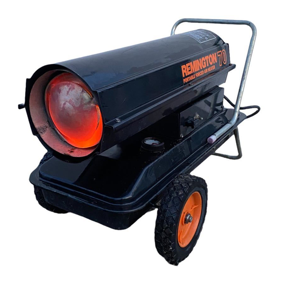
Fan Guard Fuel Gauge Air Filter End Cover Fuel Tank ON/OFF Switch Fuel Cap Side Cover Flame-Out Control Power Cord Reset Button Figure 1 - REMJ70 Hot Air Outlet Upper Shell Lower Shell Fan Guard Fuel Tank Fuel Cap Side Cover... -
Page 5: Unpacking
UNPACKING 1. Remove all packing items applied to heater for shipment. 2. Remove all items from carton. 3. Check items for any shipping damage. If heater is damaged, promptly inform dealer where you bought heater. ASSEMBLY These models are furnished with wheels and handles. Wheels, handles, and the mounting hardware are found in the shipping carton. -
Page 6: Theory Of Operation
THEORY OF The Fuel System: The air pump forces air through the air line. The air is then pushed through the burner head nozzle. This air causes fuel to lift from the tank. A OPERATION fine mist of fuel is sprayed into the combustion chamber. The Air System: The motor turns the fan. -
Page 7: Ventilation
If heater does not start, push in flame-out control reset button (see Figures 5 and 6). Flame-Out Control Flame- Reset Button Control Reset Button Figure 6 - Flame-Out Control Reset Figure 5 - Flame-Out Control Reset Button (REMJ150) Button (REMJ70) Continued 102961... -
Page 8: Storing, Transporting, Or Shipping
OPERATION To Stop Heater 1. Turn ON/OFF switch to “OFF.” Continued 2. Unplug power cord from outlet. To Restart Heater 1. Wait 2 minutes after stopping heater. 2. Repeat steps under To Start Heater, page 7. Note: If shipping, transport companies require fuel tanks to be empty. STORING, 1. -
Page 9: Troubleshooting
TROUBLE- WARNING SHOOTING Never service heater while it is plugged in, operating, or hot. Severe burns and electrical shock can occur. OBSERVED FAULT POSSIBLE CAUSE REMEDY Wrong pump pressure See Pump Pressure Heater ignites, but flame-out control Adjustment, page 12. shuts off heater after Dirty air output, air intake, See Air Output, Air Intake... -
Page 10: Service Procedures
5/16" nut-driver. These screws attach upper and lower shells together. 2. Lift upper shell off. 3. Remove fan guard. Figure 7 - Upper Shell Removal (REMJ70) Upper Shell Guard Figure 8 - Upper Shell Removal (REMJ150) Fuel Filter... -
Page 11: Fuel Filter (Remj150)
13/16" open-end wrench. 5. Clean and regap spark plug Spark electrodes as follows: Plug REMJ70: .085" (2.2 mm) gap, REMJ150: .085" (2.2 mm) gap. 6. Install spark plug in burner head. 7. Attach spark plug wire to spark plug. -
Page 12: Air Output, Air Intake, And Lint Filters
filters. Filter 5. Wash or replace air intake filter (see Preventative Maintenance Schedule, Figure 13 - Air Output, Air Intake, and Lint Filters (REMJ70) page 8). 6. Replace filter end cover. Air Intake Filter 7. Replace fan guard and upper shell. -
Page 13: Nozzle
Nozzle 1. Remove upper shell (see Combustion page 10). Chamber 2. Remove fan (see page 15). 3. Remove fuel and air line hoses from burner head. 4. Remove spark plug wire Spark Plug Wire and Rubber Cup from spark plug. Burner Head 5. -
Page 14: Pump Rotor
Rotor 4. Remove pump plate Air Output screws using 5/16" nut- Filter driver. 5. Remove pump plate. Figure 19 - Rotor Location (REMJ70) 6. Remove rotor, insert, and blades. Pump Blade Plate 7. Check for debris in pump. If debris is found, blow Intake out with compressed air. -
Page 15: Fan
Tighten setscrew firmly (40-50 inch-pounds/ Motor 4.5-5.6 n-m). Shaft 8. Replace fan guard and upper shell. Setscrew Figure 24 - Fan Cross Section SPECIFICATIONS REMJ70 REMJ150 Heat Output (Kcal/hr) 17,640 38,500 Fuel Consumption (liters/hr) Fuel Tank Capacity (liters) Run Time per Tank... -
Page 16: Illustrated Parts Breakdown And Parts List
ILLUSTRATED PARTS BREAKDOWN REMJ70 10-1 10-2 10-3 10-4 10-7 10-5 10-6 Burner Head Assembly 18-1 18-2 18-3 18-4 18-5 18-6 18-7 18-18 18-8 18-17 18-9 18-16 18-10 18-15 18-14 18-11 Motor and Pump Assembly 18-13 18-12 102961... - Page 17 PARTS LIST This list contains replaceable parts used in your heater. When ordering parts, be sure to provide the correct model and serial numbers (from the model plate), REMJ70 then the part number and description of the desired part. PART...
-
Page 18: Rem150
ILLUSTRATED PARTS BREAKDOWN REMJ150 BURNER HEAD 100 EAI/EBI PFA/P 022 Burner Head Assembly 10-1 10-3 10-2 10-4 10-5 48 43 10-6 10-7 10-18 10-8 10-17 10-9 10-16 10-10 10-15 10-14 10-11 10-13 10-12 Motor and Pump Assembly 102961... - Page 19 PARTS LIST This list contains replaceable parts used in your heater. When ordering parts, be sure to provide the correct model and serial numbers (from the model plate), then REMJ150 the part number and description of the desired part. PART PART NUMBER DESCRIPTION...
-
Page 20: Wheels And Handles
WHEELS AND HANDLES PART PART REMJ70 REMJ150 NUMBER DESCRIPTION QTY. QTY. 097198-02 Handle (Rear) — 097777-03 Handles — M12345-33 Screw, #10-24 x 1 3/4" 097197-02 Wheel Support Frame — M12831-3 Wheel Support Frame — NTC-3C Hex Nut, #10-24 097766-01 Wheel... -
Page 21: Wiring Diagram
Flame Terminal White Blue Blue Photo- Ignitor Board cell Control Spark Plug Reset Button Black Relay Figure 25 - Wiring Diagram (REMJ70) Power Plug Green Plug White Black Black Power On Switch Receptacle White Black White Green/ Motor Yellow White... - Page 22 NOTES _________________________________________________________________ _________________________________________________________________ _________________________________________________________________ _________________________________________________________________ _________________________________________________________________ _________________________________________________________________ _________________________________________________________________ _________________________________________________________________ _________________________________________________________________ _________________________________________________________________ _________________________________________________________________ _________________________________________________________________ _________________________________________________________________ _________________________________________________________________ _________________________________________________________________ _________________________________________________________________ _________________________________________________________________ _________________________________________________________________ _________________________________________________________________ _________________________________________________________________ _________________________________________________________________ _________________________________________________________________ _________________________________________________________________ _________________________________________________________________ _________________________________________________________________ _________________________________________________________________ _________________________________________________________________ _________________________________________________________________ _________________________________________________________________ _________________________________________________________________ _________________________________________________________________ _________________________________________________________________ _________________________________________________________________ _________________________________________________________________ _________________________________________________________________ _________________________________________________________________ _________________________________________________________________ _________________________________________________________________ 102961...
- Page 23 NOTES _________________________________________________________________ _________________________________________________________________ _________________________________________________________________ _________________________________________________________________ _________________________________________________________________ _________________________________________________________________ _________________________________________________________________ _________________________________________________________________ _________________________________________________________________ _________________________________________________________________ _________________________________________________________________ _________________________________________________________________ _________________________________________________________________ _________________________________________________________________ _________________________________________________________________ _________________________________________________________________ _________________________________________________________________ _________________________________________________________________ _________________________________________________________________ _________________________________________________________________ _________________________________________________________________ _________________________________________________________________ _________________________________________________________________ _________________________________________________________________ _________________________________________________________________ _________________________________________________________________ _________________________________________________________________ _________________________________________________________________ _________________________________________________________________ _________________________________________________________________ _________________________________________________________________ _________________________________________________________________ _________________________________________________________________ _________________________________________________________________ _________________________________________________________________ _________________________________________________________________ _________________________________________________________________ _________________________________________________________________ 102961...
- Page 24 102961-01 Rev. A Printed in U.S.A. 06/96 102961...