Table of Contents
Advertisement
Quick Links
Advertisement
Table of Contents

Related Manuals for IDEAL Concord ESi 140


Summary of Contents for IDEAL Concord ESi 140
- Page 1 Concord ESi 140 - 380 Your Ideal installation and servicing guide 3000145/2-001-A...
- Page 2 GENERAL Table 1 - Performance Data Boiler ESi 140 ESi 160 ESi 180 ESi 200 ESi 220 ESi 260 ESi 300 ESi 340 ESi 380 Number of Sections Boiler Output 2nd stage kW 119-140 136-160 153-180 170-200 187-220 221-260 255-300 289-340 323-380 1st stage kW 83-98 95-112 107-126 119-140 131-154 155-182 179-210 202-238 226-266...
-
Page 3: Table Of Contents
Instructions or otherwise recommended by Ideal Stelrad Group Wiring Diagrams............31 in writing. If in doubt, please enquire. Any direct connection of a control device not approved by Ideal Stelrad Group could invalidate the Certification, the normal appliance warranty and could also infringe the Gas Safety Regulations. -
Page 4: Hydraulic Resistance
GENERAL GAS CONTROLS The range of boilers is NOT suitable for: 1. Gravity DHW systems. Control is by automatic ignition of intermittent pilot; once the presence of a flame has been proved the main gas valve opens 2. Gravity heating systems. to give heat input according to thermostat settings. - Page 5 GENERAL LOW TEMPERATURE OPERATION The flow temperature from the Concord ESi boiler can be reduced to a minimum of 40ºC dependent on the heat load requirement of the system. This is permissible in those situations where low modulated temperature operation is achieved using weather compensation.
-
Page 6: Static Head Requirements
GENERAL 3 OPEN VENTED SYSTEMS - Minimum static head requirements Particular reference should be made to BS. 6644: Section 2; 2. An independent cold feed/expansion pipe connection is Subsection 10 and Guidance note PM5 "Automatically made to the redundant boiler return tapping. Cold feed/ controlled steam and hot water boilers"... -
Page 7: Installation Requirements
FOR LARGE PIPE INSTALLATIONS heat exchangers of the boiler and associated systems. Gas Installations Ideal Stelrad Group advise contact directly with specialists on water treatment such as: IGE-UP-1: Purging Procedures of Non-domestic Gas Installations. -
Page 8: Air Supply
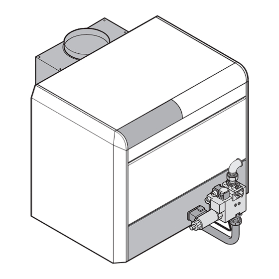
Care should be taken to ensure the specification of the chimney is suitable for the application by reference to the manufacturers literature. Ideal Stelrad Group can offer advice on the design of AIR SUPPLY BY MECHANICAL VENTILATION suitable chimney systems. - Page 9 GENERAL CONCORD ESi CON5 55 10 6 9 5. Ignition burner: it is used to ignite the main burner. An 1. Control panel: refer to Frames 37 and 39 for description, ignition electrode and an ionisation probe are fitted to the operation and electrical connections.
- Page 10 GENERAL OPERATION OF THE BOILER FITTED WITH THE RV 00 541 400 00 SAFETY CONTROL BOX - Normal operating cycle OPERATING PRINCIPLE The boiler can operate either in the 2nd or in the 1st stage, depending upon the heat requirements of the installation. The burner ignition and monitoring cycle is performed by the safety control box.
-
Page 11: Boiler Clearances
GENERAL BOILER CLEARANCES AND INSTALLATION The figures indicate the minimum recommended dimensions for providing easy access around the boiler. Boiler dimensions are given in mm. No. of boiler sections 1058 1146 1234 1406 No. of boiler sections 1322 1498 1674 1850 No. -
Page 12: Installation
INSTALLATION ASSEMBLY Tools required: 8-mm spanner Phillips head screwdriver 10-mm spanner * Simplified JD assembly tool (8 to 14 sections) or 1 * JD-TE assembly tool for any model 13-mm spanner or 1 * JD-TE Plus assembly tool for any model 19-mm spanner * Not supplied with the boiler Packaging: the tables below provide the numbers of the packages making up the boiler. -
Page 13: Combustion Chamber Removal
INSTALLATION GAS TRAIN UNPACKING CON9072 Remove the cover and the 4 sides of the gas train package. Put the brush (4) away. take out the accessories box (1) the front support (2) and the Remove the 2 blocks (5) on the front side. lower panel (3). - Page 14 INSTALLATION 11 BASE FRAME ON5262 Make the base frame level in both directions and ensure a right angle. 14 to 20 sections boilers: mount the central foot (1) on the The rear central foot is pre-assembled (14 to 20 sections front of the base frame (this is only used to assemble the models).
- Page 15 INSTALLATION 13 NIPPLE ASSEMBLY 14 NIPPLE ASSEMBLY AND SEALANT Clean the nipples (4) and coat them with the lubricant supplied with the sections. Press in the 2 nipples moderately using a hammer and a piece of wood. Carefully apply filler on the sealing grooves (5) with a Put the 2nd section in place and clean the bores with a spatula so as to ensure correct tightness of the boiler brush.
-
Page 16: System Connections
INSTALLATION 16 ASSEMBLY RODS 17 SYSTEM CONNECTIONS Fit the tie rods with M10N washers and H10 nuts. Fasten the 16 M12 studs supplied in the accessories package onto the side sections connections, taking Remove the assembly tool. care to screw the short thread of the studs in the cast Remove the central front foot. - Page 17 INSTALLATION 19 HYDRAULIC TEST Screw the plugs into the pipes (1). Screw a R2 to Rp 1/2 reduction into the heating return (2). Connect the test pump to this reduction (3). Run the test for 10 minutes. The test pressure must be equal to 9 bar. Any drop in pressure indicates a leakage in the boiler body.
- Page 18 INSTALLATION 21 ASSEMBLING THE DRAUGHT DIVERTER Stick the self-adhesive cord (1) on the top of the body. Start on the centre of the back side. Apply a silicone bead (2) as shown on the picture (only on the front side of the boiler). ON5268 22 DRAUGHT DIVERTER Remove the nuts pre-mounted on the...
- Page 19 INSTALLATION 23 JACKET SUPPORTS Mount angle (1) (supplied in the casing package) on front Put the 3 cable ties (4) in place on the control panel support (2) and fasten it using the premounted self-tapping support. screws. Stick the data plate (5) on the front support. Fasten the front support using 2 M8 x 25 screws + 2 nuts + 4 large-diameter washers.
- Page 20 INSTALLATION 25 INSULATION con9050 Put the left-hand side insulation panel (1) in place: Put the right-hand side insulation panel (3) in place inserting the bottom into the base frame. insert the bottom into the base frame, insert the top under flow pipe (2). 26 INSULATION FASTENINGS Put the lower front insulation panel on the combustion chamber square...
- Page 21 INSTALLATION 27 UPPER FRONT INSULATION Put the upper front insulation panel in place inserting it between the draught diverter and the front support. Fasten it with clamps. ON5274 28 TOP INSULATION Put the top insulation panel on the draught diverter. ON5275 Concord ESi - Installation and Servicing...
- Page 22 INSTALLATION 29 ASSEMBLING THE RIGHT-HAND SIDE PANEL Put the right-hand side panel (1) on the side angle bars of the base frame inserting the openings on the bushes (2), then lock pushing the panel backward. Fasten it on the support with 1 screw (3) + serrated washer and on the stiffener (4) with 1 self tapping screw (5).
- Page 23 INSTALLATION ASSEMBLING THE CONTROL PANEL (and accessing the sensors) con9052 Put the control panel (1) in place into the three keyhole Remove the control panel top cover (4). openings in the front support panel (1A). Remove the two top screws (5) and the two front Fasten the control panel on to the front support panel with screws (6).
- Page 24 INSTALLATION 33 ASSEMBLING THE LEFT-HAND SIDE PANEL Position the left side panel. Fit the panel onto the pins and slide to the rear (1). Fit the panel to the front support (2). Fit the panel to the stiffener (3). Close the control panel (4). Fit the 4 screwss (5) Fit the protection cap (6), securing with 2 screws.
- Page 25 INSTALLATION 35 JACKET PANELS Remove the adhesive holding tape from the flap (1). Put the upper front panel in place (2) and fasten with two self tapping screws. Put the lower rear panel (3) in place by sliding it into the fold in the rear cross-piece and secure it with self tapping screws.
- Page 26 INSTALLATION 37 ELECTRICAL CONNECTIONS (EXTERNAL) The electrical wiring has been thoroughly checked in the factory and the internal connections of the All the connections shall be made to the terminal block control panel must in no case be modified. provided for that purpose in the boiler control panel. Proceed as follows to open the control panel (if required): The electrical connections shall be made in compliance with the instructions given in the electrical diagrams...
- Page 27 INSTALLATION 38 BASIC CONNECTIONS Option kit AD212 1 Remove link 2 230 V main supply 3 Heating pump Circuit A 4 DHW pump 5 Boiler sensor 6 DHW sensor (AD212) - optional The connector supplied in the AD212 kit with the 22kOhm resistance and a 100nF capacitor, must be plugged into terminals 20 and 21.
-
Page 28: Control Panel Description
INSTALLATION 39 CONTROL PANEL DESCRIPTION CONTROL PANEL DESCRIPTION 1. General ON (1) / OFF (0) switch 10. Switch for selecting the number of burner stages (2-stage boilers) 2. Burner alarm indicator + Reset button 11. Digital display This light comes on when the safety control box is in safety lockout (out of order). - Page 29 INSTALLATION 40 CONNECTION OF COMPONENTS (NOT SUPPLIED) Remove link Safety contact The flow controller contact is connected to the terminals CS on the VA+CS connector Alarm indicator This light comes on when the safety control box is in safety lockout (out of order) Remote alarm to indicate overheat may be wired to terminals VA on the VA+CS connector.
- Page 30 INSTALLATION 41 CONNECTING THE OPTIONAL FLUE GAS THERMOMETER KIT (Package ID 28) An optional flue gas thermometer may be fitted to the front of the control panel. Proceed as follows: Cut the cover off with a knife along the edges of the coloured rectangle. Clip the thermometer into the opening.
- Page 31 INSTALLATION 44 ELECTRICAL DIAGRAMS PRINCIPAL DIAGRAM Concord ESi - Installation and Servicing...
-
Page 32: Gas Connections
INSTALLATION DISPLAY FEATURES MESSAGES - ALARMS The display may show the following messages in the case of a malfunction: Notes Message Failure Component Probable Cause Remedy Installation stops Boiler The corresponding Inform the If the power supply is interrupted with sensor sensor circuit is installer... -
Page 33: Commissioning & Testing
INSTALLATION FLUE CONNECTION 1. Complete the flue connection. 2. Details of flue outlet sizes are given in Table 2. 3. Seal with an approved boiler putty. COMMISSIONING AND TESTING GENERAL TESTING FOR GAS SOUNDNESS Check that all drain cocks are closed, that any stop valves fitted Close the gas supply cock at the meter. - Page 34 INSTALLATION SETTING PROCEDURE (all boilers) 1. Adjusting the 2nd stage pressure: Connect the pressure gauge to the manifold pressure tapping. Operate the boiler at the 2nd stage acting upon the thermostat(s). Adjust the burner injector pressure indicated in Table 1 as follows: •...
-
Page 35: Servicing
SERVICING SERVICING (to be performed by a CORGI registered installer) The burner and the heat exchanger must be cleaned regularly in order to ensure their efficiency. Cleaning is recommended at least once a year or more if necessary. WARNING Always turn OFF the gas supply at the gas cock and disconnect the electricity supply to the appliance BEFORE servicing or replacing any components. - Page 36 SERVICING CLEANING THE BOILER BODY Check the condition of the boiler body at least once a year and clean it if dirty. If the boiler needs to be swept, remove the burner (use Frame 55) from the combustion chamber in order to prevent deposits and soot falling on the burners.
- Page 37 NOTES Concord ESi - Installation and Servicing...
- Page 38 NOTES Concord ESi - Installation and Servicing...
- Page 39 NOTES Concord ESi - Installation and Servicing...
- Page 40 Technical Training The Ideal Boilers Technical Training Centre offers a series of first class training courses for domestic, commercial and industrial heating installers, engineers and system specifiers. For details of courses please ring: .... 01482 498 432 Ideal Boilers, P.O. Box 103, National Ave, Kingston upon Hull, HU5 4JN.