Kenwood R-5000 User Handbook Manual
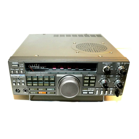
Communications receiver
Hide thumbs
Also See for R-5000:
- Service manual (128 pages) ,
- Instruction manual (36 pages) ,
- Service manual (65 pages)
Table of Contents
Advertisement
Advertisement
Table of Contents

Related Manuals for Kenwood R-5000


Summary of Contents for Kenwood R-5000
-
Page 2: Table Of Contents
EXTERNAL SPEAKER ....................10 DC POWER CABLE KIT .................... 10 VOICE SYNTHESIS UNIT ..................11 VHF CONVERTER..................... 11 REMOTE CONTROL - How to configure the R-5000 for remote control and how to use it. REMOTE CONTROL MODIFICATION ..............12 LEVEL CONVERTER....................13 REMOTE CONTROL SOFTWARE ................ -
Page 3: Introduction
DXing a breeze. With several IF filters to choose from, the user can customize his or her radio to suit their monitoring needs. This book was written to assist the owners of the R-5000 in enhancing their receivers. I have collected all of the items outlined here over the years I have owned my receiver. Some of the information was easy to find on the World Wide Web, talking to fellow owners, etc, other information was more difficult. -
Page 4: Performing Modifications
5 seconds whether or not the signal is still present. The R-5000 can be modified for Carrier Operated Scan. This mod allows the receiver to return to scan only after there is no AM or FM signal. This modification involves cutting jumper... -
Page 6: Extended Functions
When used with the Scan Busy Stop modification (see page 5), this modification makes the scan function in the R-5000 much more effective. Time Operated Scan stops on an active channel only for 5 seconds, then resumes scanning. This means you would miss the rest of the transmission if it last more than 5 seconds. - Page 7 FM Mode Step Frequency Diode D67 controls the step frequency in FM mode when the step switch is on. The standard step frequency is 2.5 kHz. With D67 cut, the step frequency is 500 Hz. This modification is only for HF-band FM mode. When the VC-20 VHF option is installed, the step frequency is already 500 Hz with the step switch on.
-
Page 8: Am Broadcast Sensitivity
AM BROADCAST SENSITIVITY The R-5000 has excellent sensitivity in the HF band. The sensitivity in the AM broadcast band is acceptable for most. If you are a hard-core AM broadcast DXer, you can increase the sensitivity in this band slightly. The input filter for this band has an attenuator on its output consisting of R9, R10 and R11. -
Page 9: Scan Speed
ADJUSTMENTS The Kenwood R-5000 has a couple of internal adjustments that the user can set for personal preferences. These are outlined below. SCAN SPEED The speed at which the receiver scans between channels or frequencies can be changed. The adjustment for this is a trimmer pot found on the Switch Unit X41-3000-00 A/8 board. -
Page 10: If Filters
The R-5000 will accept up to four filters of varying bandwidth. The filters are selected in series, with the overall bandwidth being determined by the narrowest filter used. The front panel SELECTIVITY switch gives the operator the choice of four bandwidths: N, M1, M2, W or AUTO. -
Page 11: Installing Filters
INSTALLING FILTERS Installing the optional filters is easy. The IF board is labeled with each filter position as shown in Figure 3. Simply locate the proper position for the filter you wish to install and feed the leads through the board. The filter will only go in one way. Solder the leads with a low wattage iron as quickly as possible to prevent damage to the board. -
Page 12: External Speaker
SP-23 that works but does not match the color or styling of the R-5000. DC POWER CABLE KIT The DC Power Cable Kit DCK-2 allows the R-5000 to run off 13.8 volts DC at 2 amps. It consists of a simple cable with connectors at both ends. One connector plugs into connector 5 located near the corner of the AVR board shown in Figure 4. -
Page 13: Voice Synthesis Unit
148-174 MHz. FM mode is usually used in this area except for AM in the aviation band. The VC-20 has its own antenna jack on the rear panel. This option allows the R-5000 owner to monitor local public safety communications and keep in touch with what is happening in their home town as well as across the globe. -
Page 14: Remote Control Modification
I find it most useful to mass-program the 100 channels of the R-5000 depending on my listening interest at the time. I can load all the military HF aircraft frequencies in less than 30 seconds! I can then scan those frequencies listening for Air Force One transporting the Big Guy around the world. -
Page 15: Level Converter
The IF-232C level converter can be purchased from dealers for around $100. This device converts the TTL levels that the R-5000 uses to RS-232 levels that a terminal or personal computers uses. One end plugs into the ACC connector on the back of the receiver. -
Page 16: Remote Control Software
Kenwood TS-440 amateur transceiver, but the receive part of the programs will still work. Note that the R-5000 is a “sister product” to the TS-440, but the receiver design more closely follows that of the TS-940 transceiver. -
Page 17: Remote Control Commands
REMOTE CONTROL COMMANDS This is a list of commands that control a Kenwood R-5000 Receiver. The format and spacing are critical. If blank spaces are needed I have pointed them out in the descriptions. Refer to the previous section, REMOTE INTERFACE INFORMATION for an explanation on the protocol requirements and the terminator character. - Page 18 DOWN DOWN - If the receiver is in VFO mode, moves the current VFO down in frequency according to step switch. Refer to the R-5000 manual for the step sizes for each mode. If in memory channel mode, moves the receiver down one channel.
- Page 19 FREQUENCY READ FA; = VFO A FB; = VFO B FREQUENCY READ - Receiver will send back frequency of that VFO in the format below: Fx00000000000; EXAMPLE - If you enter the command FA; and the receiver sends back FA00006955000;, this means VFO A is set at 6.955 MHz.
- Page 20 IDENTIFICATION IDENTIFICATION - Receiver will send back the ID number for the particular Kenwood model number. The R-5000 will return ID005;. EXAMPLE - If you enter the command ID; the receiver sends back ID005;. INFORMATION INFORMATION - Receiver will send back complete radio status...
- Page 21 IF0000000000000000 000000 The third position of the last field is not used and is always zero for the R-5000. IF0000000000000000 000000 Mode - The fourth position of the last field indicates the mode of...
- Page 22 EXAMPLE - If you enter the command IF; and the receiver sends back complete status of: IF0000741500001000 220520 Reading left to right, the first field states the receiver is set at 7.415 MHz and a step frequency of 1 kHz. The last field states the receiver is on channel 22, in AM mode, memory channel mode, and the radio is not scanning.
- Page 23 EXAMPLE - If you enter the command MD3; the receiver is changed to CW mode. MEMORY READ MR x x; MEMORY READ - Reads contents of memory channel x x. Two spaces between the MR and the actual channel number is necessary.
- Page 24 Channel Lock - The last position indicates whether the channel is locked out for memory scan: MR00000000000000000 ; The lockout is indicated by: 0 = NOT LOCKED OUT 1 = LOCKED OUT EXAMPLE - If you enter the command MR22; and the receiver sends back: MR00220000741500060 ;...
- Page 25 2 = USB 3 = CW 4 = FM 5 = AM 6 = FSK Channel Lock - The last position is used to lock out the channel for memory scan: MW 000000000000000 ; The lockout is indicated by: 0 = NOT LOCKED OUT 1 = LOCKED OUT EXAMPLE - If you enter the command: MW 220000741500050 ;...
- Page 26 NOTE: The scan group in Memory Scan can only be entered from the receiver. The R-5000 remembers the group from the last memory scan. The receiver will then scan that group if you initiate a memory scan from the remote. The default is all groups are selected.
- Page 27 AM mode, the step frequency will change from 1 kHz to 100 UP - If the receiver is in VFO mode, moves the current VFO up in frequency according to step switch. Refer to the R-5000 manual for the step sizes for each mode. If in memory channel mode, moves the receiver down one channel.
-
Page 28: Service Bulletins
SERVICE BULLETINS The only service bulletin I have found for the R-5000 is number SB-919 dated 7-21-87. It involves the capability to change the frequency from the remote interface. This only seems to be a issue with receivers of serial number 8049999 or less. The problem can be corrected by... -
Page 29: Appendix A - Addresses Of Interest
APPENDIX A This appendix lists the addresses, phone numbers, etc. of various Kenwood offices, dealers and electronic part stores. Also listed are some addresses from the World Wide Web that may be of interest. Kenwood USA Corporation 2201 E. Dominguez Street P.O. - Page 30 DEALERS Although the Kenwood R-5000 is no longer offered, these dealers will be able to help with repairs, accessories, etc. Some will also have generic amateur radio and shortwave information as well. Amateur Electronic Supply 5710 W. Good Hope Road...
- Page 31 Here are some radio-related pages on the World Wide Web. They may have shareware versions of the remote control programs, generic information on the Kenwood R-5000, or shortwave /amateur radio in general. Pages come and go on the Web, so I can’t guarantee these sites will always work.
-
Page 32: Appendix B - Remote Control Programs
Tuning is then as simple as clicking you mouse on the frequency. Updates to the database can be obtained from the company or the user can enter their own. Smart Kenwood Control also works with the TS-440 Transceiver. Overall this program does a great job of controlling the radio. - Page 33 Bossier City, LA 71112 3) HAMWINDOWS PLUS This program controls the R-5000 (and others) from Microsoft Windows. I have not tried this program but according the review in Monitoring Times magazine (Sept-Oct '93) it is the ultimate in a remote control program. But all these capabilities come at a high price (list is around $190).
- Page 34 It can be used to send single commands to the Kenwood R-5000, as a “poor-mans” remote control. Unfortunately the program is not as cheap as the programs listed above. Procomm Plus can be found at most computer stores, the Web at http://www.symantec.com/procomm/procomm.html, or directly from Symantec at:...
-
Page 35: Appendix C - Cmos Handling Procedures
APPENDIX C Complementary Offset Symmetry Metal-Oxide Semiconductor (CMOS) devices have diode protection against detrimental electrical conditions such as static electricity. Although these devices contain circuitry to protect their inputs against damage from high voltages, care should be taken in handling them. Severe electrical conditions can occur during handling.