Roland RS-5 Service Notes
64 voice synthesizer
Hide thumbs
Also See for RS-5:
- Owner's manual (180 pages) ,
- Owner's manual (180 pages) ,
- Owner's manual (182 pages)
Table of Contents
Advertisement
Quick Links
RS-5
TABLE OF CONTENTS
SPECIFICATIONS ................................................................................................................................................................. 1
PANEL LAYOUT .................................................................................................................................................................... 2
EXPLODED VIEW ................................................................................................................................................................. 3
PARTS LIST ........................................................................................................................................................................... 4
IDENTIFYING THE VERSION NUMBER .............................................................................................................................. 7
Saving and loading user data ................................................................................................................................................ 7
Factory Reset procedure ....................................................................................................................................................... 9
Upgrading the program memory software version ................................................................................................................. 9
TEST MODE .......................................................................................................................................................................... 11
ERROR MESSAGE ............................................................................................................................................................... 15
KEYBOARD DISASSEMBLY ................................................................................................................................................. 16
CIRCUIT BOARD(KEYBOARD) ............................................................................................................................................ 16
KEYBOARD CIRCUIT DIAGRAM .......................................................................................................................................... 17
KEYBOARD DISASSEMBLY ................................................................................................................................................. 17
BLOCK DIAGRAM ................................................................................................................................................................. 19
CIRCUIT BOARD (MAIN BOARD) ......................................................................................................................................... 20
CIRCUIT DIAGRAM (MAIN BOARD 1/4) ............................................................................................................................... 21
CIRCUIT DIAGRAM (MAIN BOARD 2/4) ............................................................................................................................... 22
CIRCUIT DIAGRAM (MAIN BOARD 3/4) ............................................................................................................................... 23
CIRCUIT DIAGRAM (MAIN BOARD 4/4) ............................................................................................................................... 24
CIRCUIT BOARD(PANEL A/B BOARD) ................................................................................................................................ 25
CIRCUIT DIAGRAM (PANEL A BOARD) .............................................................................................................................. 26
CIRCUIT DIAGRAM (PANEL B BOARD) .............................................................................................................................. 27
Copyright © 2001 by ROLAND CORPORATION
All rights reserved. No part of this publication may be reproduced in any form without the written permission of ROLAND CORPORATION.
17059088
SERVICE NOTES
First Edition
Issued by RJA
Page
Printed in Japan (A000) (CM)
SPECIFICATIONS
64-voice synthesizer (Conforms to General MIDI 2 System)
Keyboard
61 keys (with velocity)
Parts
16
Maximum Polyphony
64 voices
Wave Memory
32 M bytes (16-bit linear equivalent)
Preset Memory
Tones: 512 (RS-5 Original: 256, General MIDI 2: 256)
Performances: 128
Drum Sets: (RS-5 Original: 11, General MIDI 2: 9)
User Memory
Tones: 128
Performances: 128
Drum Sets: 2
Effects
Multi-Effects: 42 types
Reverb: 8 types
Chorus: 8 types
Arpeggiator
45 styles
Controllers
Pitch Bend/Modulation Lever
Control Knobs: 6
Display
20 characters, 2 lines (Backlit LCD)
7 segments, 3 charavters (LED)
Connectors
Output Jacks (L (MONO), R)
Headphones Jack
MIDI Connectors (IN, OUT, THRU)
Hold Pedal Jack
Control Pedal Jack
Power Supply
DC 9V (AC Adaptor)
Current Draw
600 mA
Dimensions
1033 (W) × 294 (D) × 103 (H) mm
40-11/16 (W) × 11-5/8 (D) × 4-1/16 (H) inches
Weight
6.0 kg / 13 lbs 4 oz (excluding AC adaptor)
Accessories
Owner's Manual {Japanese (#71784356), English (#71787534)}
AC Adaptor (ACI/ACB Series)
ACB-230E (#01458278)
ACB-240(A) (#12449549)
ACI-100C (#00905756)
ACI-120C (#00905767)
ACI-230C (#01018312)
Options
Pedal Switch: DP-2/6
Foot Switch: BOSS FS-5U
Expression Pedal: EV-5
* In the interest of product improvement, the specifications and/or appearance of
this unit are subject to change without prior notice.
Jan. 2001
1
Advertisement
Table of Contents

Related Manuals for Roland RS-5


Summary of Contents for Roland RS-5
-
Page 1: Table Of Contents
Copyright © 2001 by ROLAND CORPORATION All rights reserved. No part of this publication may be reproduced in any form without the written permission of ROLAND CORPORATION. 17059088 Printed in Japan (A000) (CM) -
Page 2: Panel Layout
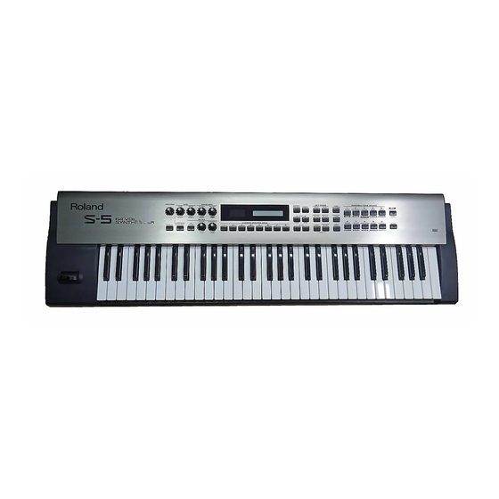
RS-5 Jan. 2001 PANEL LAYOUT Top Panel parts list PART CODE PART NAME DESCRIPTION Q'TY TOP PANEL 02453289 TOP PANEL S BLK/LCG 02452912 J R-KNOB SF-A BLK/LCG 02455234 12M/M ROTARY POT. EVJY15F02B14 02452912 J R-KNOB SF-A BLK/LCG 02455223 9M/M ROTARY POT. -
Page 3: Exploded View
RS-5 Jan. 2001 EXPLODED VIEW [PART] PART CODE PART NAME DESCRIPTION Q'TY 00896934 BOTTOM CASE 00340690 FOOT ZULEN (CUSHION) XCK040 12MM 02455956 PANEL HOLDER 71784401 PWB PANEL A ASSY 71784412 PWB PANEL B ASSY 02453312 DISPLAY COVER 22365714 CORD HOOK... -
Page 4: Parts List
RS-5 Jan . 2001 PARTS LIST BENDER UNIT 70564101 PB-H0201 BENDER TURBOLESS NOTE : Replacement PB-H0201 should be made on a unit base. The parts marked # CONSIDERATIONS ON PARTS ORDERING SAFETY PRECAUTION:*1 are new (initial When ordering any parts listed in the parts list, please specify the following items in the order sheet. - Page 5 RS-5 Jan. 2001 00567256 RPC05T 562 J MTL.FILM RESISTOR R92,R91,R48,R49,R50,R51, TRANSISTOR R81,R82 on MAIN BOARD 01011856 RPC05T 0R0 J MTL.FILM RESIST0R R142,R3,R111,R98,R69,R64,R44, 01121278 2SA1576A T106 QRS TRANSISTOR Q6 on MAIN BOARD R41,R11,R35,R27,R25,R24,R23, 15309101 2SA1037AKT146R TRANSISTOR Q24,Q25 on MAIN BOARD R38,R144 on MAIN BOARD...
- Page 6 RS-5 Jan . 2001 01674612 ECJ1VB1H103K CERAMIC CAPACITOR C129,C127,C126,C124,C184,C125, SCREW C192,C128,C241,C242 40011034 SCREW 3X8 PAN TAPTITE B ZC on MAIN BOARD 40011056 SCREW 3X6 BINDING TAPTITE B ZC 4 +15 01674212 ECUV1H220JCV CERAMIC CAPACITOR C40,C41 on MAIN BOARD 40011123 SCREW 4X8...
-
Page 7: Identifying The Version Number
RS-5 Jan. 2001 IDENTIFYING THE VERSION Saving and loading user data NUMBER Items required:Sequencer(XP-80,MC-80,etc) 1. Checking the version number MIDI cable Turn on the power while pressing the [PERFORM/TONE], [USER/PRESET] and [1/PIANO] buttons. You can save the user data to an external sequencer (Bulk Dump) The title screen of the test mode appears and the version of each CPU and ROM is displayed. - Page 8 Restoring saved settings to the RS-5 4. Press [ENTER]. Be aware that when you restore data to the RS-5, the data in the RS-5 will be overwritten and lost. 5. Use the VALUE [-]/[+] to select the types of Bulk Dump.
-
Page 9: Factory Reset Procedure
2. Use VALUE [-]/[+] to select "Factory Reset." Upgrading 3. Press [ENTER]. 1. Connect the MIDI cable to the RS-5 MIDI IN from the MIDI OUT of the external sequencer. 4. Use the VALUE [-]/[+] to select the types of Factory Reset. - Page 10 RS-5 Jan. 2001 Upgrading is much easier when using a sequencer with a chain playback function such as the MC-80.Loading and playing the “.svc” files (chain files) on the disk will automatically playback all of the “mid.’ files on the disk as well.
-
Page 11: Test Mode
* Do not turn off the power while factory resetting. Turn off the power after terminating factory resetting. Testing items Details on Testing Items The RS-5 includes the following tests. 0 : Test Mode Title For details on each tests, refer to each item. 0 : Test Mode Title... - Page 12 RS-5 Jan. 2001 1 : Memory Test 3 : Switch & LED Test • Check the CPU and FLASH ROM (PROGRAM MEMORY). • All the LEDs will light up when entering this test. • Pressing the switch will display the switch name on the screen.
- Page 13 RS-5 Jan. 2001 [VALUE] [Contrast value] [7-segment display] [LCD] 6 : A/D Test 2 ----------------------------------------------------------------------------- Contrast(Max) ] All segments go out − Contrast(1) [1.1.1.] All segments light up ↑ ↓ Contrast(2) [2.2.2.] ↓ Contrast(3) [3.3.3.] • Check control knob function.
- Page 14 RS-5 Jan. 2001 8 : Keyboard Test • Then remove the audio cable from OUTPUT R and check if two sawtooth waves, F4 and F5, are output from OUTPUT L.(Check L MONO) • Pressing [ENTER] proceeds to the next test.
-
Page 15: Error Message
Check the following parts. MAIN BOARD IC34 ERROR MESSAGE This section explains the meaning of the various error messages that the RS-5 may display, and describes the measures to take when these appear. Error Message List BULK DUMP Checksum Error... -
Page 16: Keyboard Disassembly
RS-5 Jan. 2001 KEYBOARD DISASSEMBLY CIRCUIT BOARD(KEYBOARD) SK-961-B PARTS LIST PARTS No. PARTS NAME Qty. 00893723 SK-9 NATURAL KEY CF 00893734 SK-9 NATURAL KEY EB 00893756 SK-9 NATURAL KEY D 00893767 SK-9 NATURAL KEY G 00893745 SK-9 NATURAL KEY A... -
Page 17: Keyboard Circuit Diagram
RS-5 Jan. 2001 KEYBOARD CIRCUIT DIAGRAM KEYBOARD DISASSEMBLY <ATTACHING RUBBER SWITCH and CIRCUIT BOARD> Use screws which VWH TAPTIGHT B 3X10MM ZC(#40233545) to fixed SIRCUIT BOARD in SK-9. 1) Turn over the keyboard as shown in Flg. 1 . Place the RUBBER SWITCH 12P on 4 chassis, from the left (lowest note) upward, with respect to slots in the chassis. - Page 18 RS-5 Jan. 2001 2) Align notch of the LOW PCB with projection from the chassis <Removing the keyboard> and then insert the PCB into the chassis hook until the chassis's Holding the tip of the key, insert a pair of long nose pliers positioning reference pin (located closest to the connector, into the U groove (shaded in Fig.6) and then push the key...
-
Page 19: Block Diagram
RS-5 Jan. 2001 BLOCK DIAGRAM ADPV... -
Page 20: Circuit Board (Main Board)
RS-5 Jan. 2001 CIRCUIT BOARD (MAIN BOARD) -
Page 21: Circuit Diagram (Main Board 1/4)
RS-5 Jan. 2001 CIRCUIT DIAGRAM (MAIN BOARD) 1/4 IC1C H D 7 4 L S 0 5 F P YKF51-5046 IC1G 47/6.3 H D 7 4 L S 0 5 F P 47/6.3 A[0..1] D[0..7] F W P DTA124EUA R 1 0... -
Page 22: Circuit Diagram (Main Board 2/4)
RS-5 Jan. 2001 CIRCUIT DIAGRAM (MAIN BOARD) 2/4 Q 2 6 2SC3265Y M A 1 4 2 W K R140 3.3K LGR4609-7000 C207 IC30 N1608Z601 AN78L05M H O L D 100/16 H O L D O U T C208 C209... -
Page 23: Circuit Diagram (Main Board 3/4)
RS-5 Jan. 2001 CIRCUIT DIAGRAM (MAIN BOARD) 3/4 C137 IC29 T C 7 4 H C 2 3 8 F C160 C161 C162 S S 2 S S 2 S S 1 D S S 6 100P 220P S S 1... -
Page 24: Circuit Diagram (Main Board 4/4)
RS-5 Jan. 2001 CIRCUIT DIAGRAM (MAIN BOARD) 4/4 LGR4609-7100 C 5 1 47/6.3 R 4 8 R 4 9 5.6K 5.6K C 5 3 IC13 C 5 5 W A 1 4 W A 1 4 W A 3 W A 3... -
Page 25: Circuit Board(Panel A/B Board)
RS-5 Jan. 2001 CIRCUIT BOARD (PANEL A/B BOARD) -
Page 26: Circuit Diagram (Panel A Board)
RS-5 Jan. 2001 CIRCUIT DIAGRAM (PANEL A BOARD) D S S 2 LPD[0..7] 1SS133 1SS133 1SS133 S W 1 S W 2 S W 3 E V Q 1 1 A 0 5 R E V Q 1 1 A 0 5 R... -
Page 27: Circuit Diagram (Panel B Board)
RS-5 Jan. 2001 CIRCUIT DIAGRAM (PANEL B BOARD) D S S 6 D 1 2 D 1 3 D 1 4 D 1 5 D 1 6 D 1 7 1SS133 1SS133 1SS133 1SS133 1SS133 1SS133 S W 1 2...