
Related Manuals for Danfoss OSPE


Summary of Contents for Danfoss OSPE
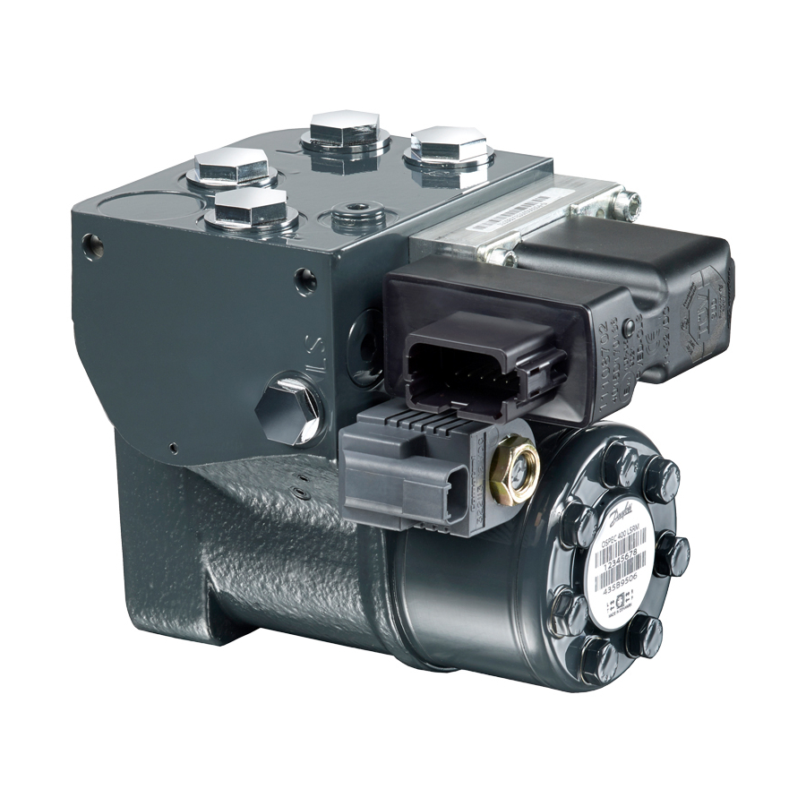
- Page 1 MAKING MODERN LIVING POSSIBLE Service Manual Steering Valve OSPE powersolutions.danfoss.com...
- Page 2 Service Manual OSPE Steering Valve Revision history Table of revisions Date Changed August 2015 Codenumber changed 0001 February 2015 First edition L1506577 • Rev 0001 • August 2015...
-
Page 3: Table Of Contents
Assembly Assembling OSPE................................... 26 Test and valve setting of OSPE Set up for testing....................................42 Set up OSPE with integrated priority valve........................42 Set up OSPE without integrated priority valve......................43 Steering test.....................................43 Pilot relief valve....................................44 Neutral positioning test, OSP part............................44 Neutral positioning test, EH part.............................. -
Page 4: Safety Precautions
Service Manual OSPE Steering Valve Safety Precautions Safety Precautions Always consider safety precautions before beginning a service procedure. Protect yourself and others from injury. Take the following general precautions whenever servicing a hydraulic system. Warning Unintended Machine Movement Unintended movement of the machine or mechanism may cause injury to the technican or bystanders. -
Page 5: Service Literature
OSPE versions This service literature is valid for: • All OSPE’s with single stage gear set • All OSPED with dual gear set. For the gear set end however only for V2/OSPED in new design If the OSPED in question is in “old” or “V2/new” design can be traced by the product code: •... -
Page 6: Exploded View And Seal Kit
Service Manual OSPE Steering Valve Exploded View and Seal Kit OSPE exploded view OSPED OSPE DEUTSCH DEUTSCH P301 786 L1506577 • Rev 0001 • August 2015... -
Page 7: Ospe Parts List
Valve plate Washers End cover O-ring Ø79.4 x Ø2.0 mm (OSPED) O-ring Ø79.4 x Ø2.0 mm (OSPE) O-ring Ø9.0 x Ø1.5 mm O-ring Ø6.0 x Ø1.5 mm Balls for shock valves Ø4.8 mm Spring with thrust pad for shock valves Valves seats 5.5 ±0.5 Nm... - Page 8 Service Manual OSPE Steering Valve Exploded View and Seal Kit OSPE parts list (continued) OSPE Number per unit Item Tigtening torque Plug 45 ±5 Nm Plugs 45 ±5 Nm Spring Cone pilot supply Spool pilot supply Plug 30 ±3 Nm Check valve, LS 3.5 ±0.5 Nm...
- Page 9 Service Manual OSPE Steering Valve Exploded View and Seal Kit OSPE seal kit and spare parts Spare parts list Code No. Item Coil, Deutsch ® : D08 12V DE 322113 11084688 Coil, AMP: D08 12V AJE 321930 11084690 Spare part bag containing:...
-
Page 10: Tools
Tools Tools for OSPE Tools Holding tool for the entire steering valve. 120±2 Material: Appropriate metal or hard plastic 90±1 1x45˚ This tool is not available from Danfoss. 2xø15±0.1 ø46±0.5 90±1 93±0.5 150±2 P301 787 Assembly tool for dust seal. - Page 11 2 - 2.75 – 3 – 4 – 5 – 6 and 8 mm Hex key. 12 mm screwdriver. 2 mm screwdriver. 13 – 17 – 19 – 7/8 inch mm ring spanner. Inside circlip pliers Plastic hammer. Tweezers. These tools are not available from Danfoss. L1506577 • Rev 0001 • August 2015...
-
Page 12: Dismantling
Service Manual OSPE Steering Valve Dismantling Dismantling OSPE Dismantling OSPE Place the unit in the holding tool on steering column end. Screw out the 4 screws for the PVE (233) using a 5 mm Hex key. Remove the PVE (204). - Page 13 Dismantling Dismantling OSPE (continued) Remove the EH L&R cut off spool (242). Screw out the plug (207). If the OSPE is with priority valve integrated: Use a 17 mm socket or ring spanner. O-ring (312) is fitted on plug (207).
- Page 14 Service Manual OSPE Steering Valve Dismantling Dismantling OSPE (continued) Screw off the nut (248) using a 19 mm socket or ring spanner. Remove the O-ring (249). Lift off the coil (247). Screw out the cartridge spool (246) using a 7/8 inch ring spanner.
- Page 15 Service Manual OSPE Steering Valve Dismantling Dismantling OSPE (continued) Replace the unit in the holding tool on the gear set end. Use appropriate support made of plastic, brass or aluminum under the mounting surface for the PVE to support the steering valve.
- Page 16 Screw out the plugs (209) using an 8 mm Hex key. O-ring (311) is fitted on plug (209) The left side positioned plug is only present on OSPE’s with priority valve integrated. Replace the unit in the holding tool on steering column end.
- Page 17 Screw out the pilot relief valve cartridge (95) using special key Danfoss code 155L6494. Screw out the orifice (222) using a 3 mm Hex key. This orifice is not present in all OSPE’s. L1506577 • Rev 0001 • August 2015...
- Page 18 Dismantling OSPE (continued) Screw out the LS check valve (221) using a 3 mm key. This check valve is not present in all OSPE’s. Screw out the plugs (253) and (254) using a 6 mm Hex key. These plugs not present in all OSPE’s.
- Page 19 Service Manual OSPE Steering Valve Dismantling Dismantling OSPE (continued) OSPED: Lift the gearwheel set (115) off the unit. Remove the two O-rings (39). OSPED: Remove the distributor plate (117). OSPED: Remove valve housing assembly (122). Remove the two O-rings (39).
- Page 20 Service Manual OSPE Steering Valve Dismantling Dismantling OSPE (continued) OSPED: Remove the cardan shaft (120). Lift the gearwheel set (30) off the unit. Remove the two O-rings (39). Remove the cardan shaft (13). Remove the distributor plate (34) from the housing.
- Page 21 Service Manual OSPE Steering Valve Dismantling Dismantling OSPE (continued) Remove the O-ring (6) from housing. Screw out threaded bushing/ball stop (4) from housing using a 12 mm screw driver and remove bushing from housing. Screw out the screw (85) using a 12 mm screw driver.
- Page 22 Service Manual OSPE Steering Valve Dismantling Dismantling OSPE (continued) Screw out the pin bolts (80) using a 4 mm Hex key. Screw out the plug (216) using a 6 mm Hex key. O- ring 314 is fitted on plug (216).
- Page 23 Service Manual OSPE Steering Valve Dismantling Dismantling OSPE (continued) Screw out the plug (225) using a 5 mm Hex key. Remove spool (224) using a 4 mm screw. Shake out the check valve ball (5), suction valve balls (81), cone (214) and spring (213).
- Page 24 Service Manual OSPE Steering Valve Dismantling Dismantling OSPE (continued) Press the spool (1) inwards (from the steering column end) and the sleeve (1), ring (16), neutral position springs (14) and bearing assembly (18) will be pushed out of the housing together.
- Page 25 Service Manual OSPE Steering Valve Dismantling Dismantling OSPE (continued) Press the neutral position springs (14) out of the slot of the spool. Remove dust seal (9) and shaft seal (Roto Glyd) (7) carefully with a screw driver or similar tool.
-
Page 26: Assembly
Service Manual OSPE Steering Valve Assembly Assembling OSPE Assembling OSPE Place the two flat neutral position springs (from item 14) in the slot of the spool (from item 1). Place the curved springs between the flat ones and press them into place. - Page 27 Service Manual OSPE Steering Valve Assembly Assembling OSPE (continued) Line up the spring set (14). Guide the ring (16) down over the sleeve. The ring should be able to move free of the springs Fit the cross pin (12) into the spool/sleeve set (1).
- Page 28 Service Manual OSPE Steering Valve Assembly Assembling OSPE (continued) Caution Assembly pattern for standard bearing 1. Outer bearing race 2. Needlebearing 3. Inner bearing race 4. Spool 5. Sleeve * The inside chamfer on the inner bearing race must face the chest of the inner spool.
- Page 29 Service Manual OSPE Steering Valve Assembly Assembling OSPE (continued) Press and turn the shaft seal (7) into position in the housing. Draw the inner and outer parts of the assembly tool out of the steering unit bore, leaving the guide from the inner part in the bore.
- Page 30 Service Manual OSPE Steering Valve Assembly Assembling OSPE (continued) Put the check valve ball (5) into the hole indicated by the circle. Screw in the screw (4) using a 12 mm screw driver. 1.5 ±0.3 Nm. Assemble spring (86) and cone (87 on screw (85).
- Page 31 Service Manual OSPE Steering Valve Assembly Assembling OSPE (continued) Screw in the pin bolts (80) using a 4 mm Hex key. 3 ±0.5 Nm. Place the spool (224) in the hole indicated by the circle. Screw in the plug (225) using a 5 mm Hex key.
- Page 32 Service Manual OSPE Steering Valve Assembly Assembling OSPE (continued) Place the spring (213), cone (214) and spool (215) in the hole indicated by the circle. Place the O-ring (314) on plug (216). Screw in the plug (216) using a 6 mm Hex key.
- Page 33 Place the gear wheel side with all the deeper splines facing downwards. Only this side will fit on the cardan shaft due to all gear sets used in OSPE have timing securing: splines of gear wheel and cardan shaft can only be assembled with correct timing.
- Page 34 Service Manual OSPE Steering Valve Assembly Assembling OSPE (continued) OSPED: Place and rotate the cardan shaft (120) with the big diameter end until it moves in gear with gear wheel of gear set (30). OSPED: Place the middle distributor plate (116) so that the channel holes match the holes in the gear set.
- Page 35 Place the gear wheel side with all the deeper splines facing downwards. Only this side will fit on the cardan shaft due to all gear sets used in OSPE have timing securing: splines of gear wheel and cardan shaft can only be assembled with correct timing.
- Page 36 Service Manual OSPE Steering Valve Assembly Assembling OSPE (continued) The OSPE can now be function tested manually: it must be possible to rotate input shaft with torque < 3.5 Nm [31 lbf•in]. Place the dust seal ring (9) in the housing.
- Page 37 Service Manual OSPE Steering Valve Assembly Assembling OSPE (continued) Place springs with trust pads (62) over the two balls. Place O-rings (40) on adjusting screws (64). Screw in the two adjusting screws (64) using a 5 mm Hex key. After entire assembly of the steering valve, make the...
- Page 38 Place O-rings (311) on plugs (209). Screw in the plugs (209) using a 8 mm Hex key. 45 ±5 Nm The left side positioned plug is only present on OSPE’s with priority valve integrated. Replace the unit in the holding tool on steering column end.
- Page 39 Place O-rings (330, 331, 332) on cartridge spool (246). Screw in the cartridge spool (246) using a 7/8 inch ring spanner. 15 ±2 Nm. OSPE with priority valve: Assemble spool (203) with the PP orifice (230) using a 3 mm Hex key. 3.5 ±0.5 Nm.
- Page 40 Service Manual OSPE Steering Valve Assembly Assembling OSPE (continued) OSPE with priority valve: Place the O-ring (312) on plug (207 with 17 mm key profile). Screw in the plug (207) using a 17 mm socket spanner 45 ±5 Nm. OSPE without priority valve: Place the O-rings (312, 313) on plug (207 with 8 mm Hex key profile).
- Page 41 (205). Place O-rings (320, 321, 322) and filter (323) on PVE (204). Place the PVE (204) on OSPE housing as illustrated and screw in the 4 screws for the PVE (233) using a 5 mm Hex key.
-
Page 42: Test And Valve Setting Of Ospe
Service Manual OSPE Steering Valve Test and valve setting of OSPE This section describes minimum tests needed, when the OSPE steering valve has been disassembled and reassembled. OSPEDC LSRM with integrated priority valve: Electronics P301 171 Set up for testing A universal hydraulic work bench is required for this setup. -
Page 43: Set Up Ospe Without Integrated Priority Valve
OSPE Steering Valve Test and valve setting of OSPE 4. If OSPE with PVES, PVED CC, or PVED CL, connect battery power cables with on/off switch to the coil of control valve for mode select (247). Voltage must meet the specification for the code. -
Page 44: Pilot Relief Valve
Neutral positioning test, EH part For OSPE with PVES, PVED CC, PVED CL: Apply battery power to the coil (item 247 on exploded view). Apply battery power and input signal to the PVE: observe that the steering cylinder is moving according to direction of input signal for PVE. -
Page 45: Check For External Leakage
Service Manual OSPE Steering Valve Test and valve setting of OSPE Adjust the pressure (R-T/L-T) by adjusting screws of shock valves (item 64) to the specified value for the shock valve setting for the code in question. Check for external leakage After testing of the former items, the steering column (wheel) and port connections are removed. -
Page 46: Tightening Torques
Service Manual OSPE Steering Valve Tightening Torques Tightening torques for connections OPSE Tightening Torques for Connections OSPD V2 Connections Maximum tightening torque Nm [lbf.in] With cutting edge With copper washer With alum. Washer O-ring M12 • 1.5 30 [265] 20 [177]... - Page 47 Service Manual OSPE Steering Valve L1506577 • Rev 0001 • August 2015...
- Page 48 Phone: +86 21 3418 5200 Danfoss can accept no responsibility for possible errors in catalogues, brochures and other printed material. Danfoss reserves the right to alter its products without notice. This also applies to products already on order provided that such alterations can be made without changes being necessary in specifications already agreed.