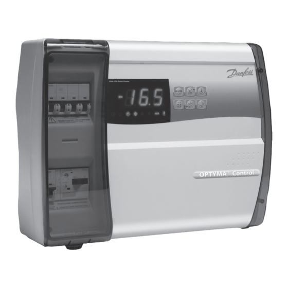
Danfoss OPTYMA Operation And Maintenance Manual
Control three-phase
Hide thumbs
Also See for OPTYMA:
- User manual (20 pages) ,
- Instructions manual (104 pages) ,
- User manual (16 pages)

Related Manuals for Danfoss OPTYMA


Summary of Contents for Danfoss OPTYMA
- Page 1 MAKING MODERN LIVING POSSIBLE OPTYMA Control Three-phase REFRIGERATION & Operation and Maintenance Guide AIR CONDITIONING DIVISION...
-
Page 3: Table Of Contents
Password function ..................................21 Alarm/AUX RELAY SWITCHING ..............................22 Alarm codes ......................................24 Trouble shooting ..................................... 25 General safety instructions ................................. 26 Maintenance ....................................26 Parts list ........................................ 27 Ordering ....................................... 28 © Danfoss A/S (RA Marketing/MWA), Nov. 08 RS8FE102, 080R9278... -
Page 4: General
(man-in-cold-room alarm in preset models). supply. - Evaporator fan control. - Adjustable motor circuit breaker for compressor protection accessible from the front panel (in - Automatic and manual defrost control (static, preset models). heating element). © Danfoss A/S (RA Marketing/MWA), Nov. 08 RS8FE102, 080R9278... -
Page 5: Technical Characteristics Of Optyma
6000W (AC1) eq. resistive load 9000W (AC1) eq. resistive load Room light 800W (AC1) resistive load 800W (AC1) resistive load Solenoid valve present present Compressor oil heater present present Alarm relay 100W 100W © Danfoss A/S (RA Marketing/MWA), Nov. 08 RS8FE102, 080R9278... -
Page 6: Connection Diagrams
OPTYMA Control three-phase Operation and Maintenance Guide Connection diagrams Overall dimensions Dimensions in mm. © Danfoss A/S (RA Marketing/MWA), Nov. 08 RS8FE102, 080R9278... -
Page 7: Identification Data
• Install the device away from fire and heat sources and protect from the weather if necessary. maintain the protection rating, use appropriate cable glands and plugs to ensure a good seal. © Danfoss A/S (RA Marketing/MWA), Nov. 08 RS8FE102, 080R9278... -
Page 8: Installing The Unit
Installing the unit Lift the transparent cover protecting the general magnetothermic circuit breaker. Remove the screw cover on the right-hand side. Undo the 4 fixing screws on the front of the cover. © Danfoss A/S (RA Marketing/MWA), Nov. 08 RS8FE102, 080R9278... - Page 9 Bend the hinges and rotate the front panel by 180° downward to gain access to the inside of the panel; then disconnect the electronic card connector. © Danfoss A/S (RA Marketing/MWA), Nov. 08 RS8FE102, 080R9278...
- Page 10 Using a screwdriver, tap out the tabs in the 4 holes in the back panel in preparation for fixing it to the wall. Using the drilling guide provided, drill 4 fixing holes in the wall. © Danfoss A/S (RA Marketing/MWA), Nov. 08 RS8FE102, 080R9278...
-
Page 11: Electrical Wiring
• Minimise the length of connector wires so that wiring does not twist into a spiral shape, as this could have a detrimental effect on the elec- tronics. © Danfoss A/S (RA Marketing/MWA), Nov. 08 RS8FE102, 080R9278... -
Page 12: Front Panel Connection
When using Alarm/Aux relay, connect the wiring directly to the electronic card clamps. It is advisable to route these wires alongside the connection cables from the electronic card and the housing back panel. © Danfoss A/S (RA Marketing/MWA), Nov. 08 RS8FE102, 080R9278... -
Page 13: Checks Before Use
(if present) correctly as shown on the a padlock for max. safety, before tightening following pages. the screws. Before any operation, use a voltage detector to check that there is no voltage. © Danfoss A/S (RA Marketing/MWA), Nov. 08 RS8FE102, 080R9278... -
Page 14: Calibrating The Compressor Motor Circuit Breaker
Warning: An incorrect calibration may cause compressor breakdown or bad intervention of the motor circuit breaker. To calibrate use the control screw on the front of motor circuit breaker. © Danfoss A/S (RA Marketing/MWA), Nov. 08 RS8FE102, 080R9278... -
Page 15: Closing The Control
Replace the screw cover on the right-hand side. Power up the control and carry out thorough reading/ programming of all the parameters. © Danfoss A/S (RA Marketing/MWA), Nov. 08 RS8FE102, 080R9278... -
Page 16: Control Panel
AU=1) UP / MUTE WARNING BUZZER STAND BY (The LED flashes if the system shuts down) Room temperature SETTING / SET key DOWN / MANUAL DEFROST ROOM LIGHT © Danfoss A/S (RA Marketing/MWA), Nov. 08 RS8FE102, 080R9278... -
Page 17: Led Display
2. Hold down the SET key and press the () or () keys to modify the SETPOINT. Release the SET key to return to cold room temperature display: the new setting will be saved automatically. © Danfoss A/S (RA Marketing/MWA), Nov. 08 RS8FE102, 080R9278... -
Page 18: Level 1 - Programming (User Level)
Above value A2 an alarm trips: the alarm LED flashes, the displayed temperature flashes and the buzzer sounds to indicate the problem. Evaporator sensor temperature display Displays read evaporator only temperature (displays nothing if dE =1) © Danfoss A/S (RA Marketing/MWA), Nov. 08 RS8FE102, 080R9278... -
Page 19: Level 2 - Programming (Installer Level)
Fan shutdown temperature -45 - +45°C +45°C The fans will stop if the temperature value detected by the evaporator sensor is higher than this value. Fan differential below Fst 0 - +10K © Danfoss A/S (RA Marketing/MWA), Nov. 08 RS8FE102, 080R9278... -
Page 20: Switching On The Optyma
(d2) is lower than the temperature detected by the evaporator sensor. Defrosting ends when the end of- defrost temperature (d2) or maximum defrost time (d3) is reached. © Danfoss A/S (RA Marketing/MWA), Nov. 08 RS8FE102, 080R9278... -
Page 21: Pump-Down Function
See parameter P1 for the different protection types. set key to confirm it. Use the universal number 100 if When PA is set, protection starts after two you have forgotten the password. © Danfoss A/S (RA Marketing/MWA), Nov. 08 RS8FE102, 080R9278... -
Page 22: Alarm/Aux Relay Switching
2. Bend the hinges and rotate the front panel downwards 180° to gain access to the electronic card. 3. Undo the 6 CPU board cover fixing screws: remove the board from the front panel of the housing in ABS. © Danfoss A/S (RA Marketing/MWA), Nov. 08 RS8FE102, 080R9278... - Page 23 6. If Alarm/Aux relay is used, wire directly on the electronic card clamps. It is advisable to route that wiring beside the connection cables from electronic card and the housing back panel. © Danfoss A/S (RA Marketing/MWA), Nov. 08 RS8FE102, 080R9278...
-
Page 24: Alarm Codes
OPTYMA Control three-phase Operation and Maintenance Guide Alarm codes In the event of any anomalies, the OPTYMA Control panel. If an alarm is tripped, the display will show one warns the operator by displaying alarm codes and of the following messages:... -
Page 25: Trouble Shooting
Make bridges on terminal block to accommodate devices not present in the system (Kriwan, pressure switches). No defrosting Incorrect setting of defrosting cycle parameters • Check that the parameters are set correctly. cycle occurs © Danfoss A/S (RA Marketing/MWA), Nov. 08 RS8FE102, 080R9278... -
Page 26: General Safety Instructions
Device Type of operation Frequency Terminal block Wires tightening After first 20 days of functioning Terminal block Wires tightening Annual © Danfoss A/S (RA Marketing/MWA), Nov. 08 RS8FE102, 080R9278... -
Page 27: Parts List
Connector for linking control and electronic card Housing front panel Electronic card Electronic card cover Electronic card fixing screws Housing closure screws Auxiliary terminal block X1 Power terminal block X2 Note! This part list is purely indicative. © Danfoss A/S (RA Marketing/MWA), Nov. 08 RS8FE102, 080R9278... -
Page 28: Ordering
Control, three-phase (4 HP) including two sensors 7-10 A 080Z3202 OPYTMA Control, three-phase (7.5 HP) including two sensors 11-16 A 080Z3206 OPYTMA Control, three-phase (7.5 HP) including two sensors 14-20 A 080Z3207 Spare sensor (EKS 221) 084N3210 © Danfoss A/S (RA Marketing/MWA), Nov. 08 RS8FE102, 080R9278...