Advertisement
Table of Contents
- 1 Table of Contents
- 2 Service Manual
- 3 Part Names and Functions
- 4 Technical Changes
- 5 Specification
- 6 Noise Criteria Curves
- 7 Outlines and Dimensions
- 8 Refrigerant System Diagram
- 9 Wiring Diagram
- 10 Microprocessor Control
- 11 Wireless Remote Controller
- 12 Service Functions
- 13 Troubleshooting
- 14 Disassembly Instructions
- 15 Parts List
- Download this manual
SPLIT-TYPE, AIR CONDITIONERS
SPLIT-TYPE, HEAT PUMP AIR CONDITIONERS
SERVICE MANUAL
Wireless type
Models
MSC-A07YV -
MSC-A09YV -
MSC-A12YV -
Indication of model name
MSC-A07YV -
MSC-A09YV -
MSC-A12YV -
NOTE:
•This manual describes technical data of indoor units.
•As for outdoor units MU-A07/A09/A12YV -
•As for outdoor units MUH-A07/A09/A12YV -
•As for outdoor units MUX-A10/A19/A20/A25/A26WV -
EDITION-A.
•As for outdoor units MUX-A22WV -
•As for outdoor units MXZ-A18/A26/A32WV -
(WH)
E1
(WH)
E1
(WH)
E1
CONTENTS
1. TECHNICAL CHANGES ····································3
2. PART NAMES AND FUNCTIONS······················3
3. SPECIFICATION·················································5
4. NOISE CRITERIA CURVES ·······························6
5. OUTLINES AND DIMENSIONS ·························7
6. WIRING DIAGRAM ············································8
E1
7. REFRIGERANT SYSTEM DIAGRAM ················8
E1
8. MICROPROCESSOR CONTROL ······················9
E1
9. SERVICE FUNCTIONS ····································17
10. TROUBLESHOOTING······································19
11. DISASSEMBLY INSTRUCTIONS·····················26
12. PARTS LIST······················································28
, refer to the service manual OB330.
E1
, refer to the service manual OB331.
E1
, refer to the service manual OB307 REVISED
E1
, refer to the service manual OB318.
E1
, refer to the service manual OB319.
E1
HFC
utilized
R410A
No. OB329
Advertisement
Table of Contents

Related Manuals for Mitsubishi Electric MSC-A07YV-E1


Summary of Contents for Mitsubishi Electric MSC-A07YV-E1
-
Page 1: Table Of Contents
SPLIT-TYPE, AIR CONDITIONERS SPLIT-TYPE, HEAT PUMP AIR CONDITIONERS No. OB329 utilized SERVICE MANUAL R410A Wireless type Models MSC-A07YV - (WH) MSC-A09YV - (WH) MSC-A12YV - (WH) CONTENTS 1. TECHNICAL CHANGES ····································3 2. PART NAMES AND FUNCTIONS······················3 3. SPECIFICATION·················································5 4. NOISE CRITERIA CURVES ·······························6 5. -
Page 3: Technical Changes
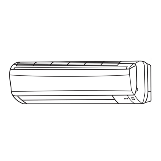
TECHNICAL CHANGES MSC-A07WV- MSC-A07YV- MSC-A09WV- MSC-A09YV- MSC-A12WV- MSC-A12YV- 1. Design of front panel has changed. 2. Air filter has changed to the catechin air filter. PART NAMES AND FUNCTIONS MSC-A07YV - MSC-A09YV - MSC-A12YV - INDOOR UNIT Front panel Air cleaning filter (white bellows type) Air inlet to Breaker... - Page 4 MSC-A07YV- MSC-A09YV- MSC-A12YV- ACCESSORIES <Indoor unit> Installation plate Installation plate fixing screw 4 o 25 mm Remote controller holder Fixing screw for 3 3.5 o 16 mm Battery (AAA) for remote controller Wireless remote controller Felt tape (Used for left or left-rear piping) Air cleaning filter REMOTE CONTROLLER Signal transmitting section...
-
Page 5: Specification
SPECIFICATION Indoor model MSC-A07YV - MSC-A09YV - MSC-A12YV - Cooling Heating Cooling Heating Cooling Heating Function Single phase Single phase Single phase Indoor unit power supply 230V,50Hz 230V,50Hz 230V,50Hz K /h Capacity Air flow(High/Med. /Low ) 474/372 /276 510/420 /342 474/384 /306 588/456 /342 582/444 /324... -
Page 6: Noise Criteria Curves
NOISE CRITERIA CURVES MSC-A07YV- MSC-A09YV- FAN SPEED FUNCTION SPL(dB LINE SPL(dB LINE FAN SPEED FUNCTION COOL COOL High High HEAT HEAT Test conditions, Test conditions. Cooling : DB27: WB19: Cooling : DB27: WB19: Heating : DB20: WB -: Heating : DB20: WB -: NC-70 NC-70... -
Page 7: Outlines And Dimensions
OUTLINES AND DIMENSIONS MSC-A07YV - Unit: mm 81.5 133.5 MSC-A09YV - Installation plate INDOOR UNIT Indoor unit 81.5 81.5 Wall hole Installation plate Liquid line 6.35-0.5m Gas line 9.52-0.43m Air in Insulation 37 O.D 21 I.D Drain hose (Connected part O,D) Insulation Air out Power supply cord... -
Page 8: Wiring Diagram
WIRING DIAGRAM MSC-A07YV - MSC-A09YV - MSC-A12YV - MODELS WIRING DIAGRAM INDOOR UNIT TO OUTDOOR UNIT TAB12 RT12 CONNECTING CN201 RT11 MUH OR MXZ TYPE NR11 CN202 MU OR MUX TYPE SR141 CN211 POWER LD103 ELECTRONIC CONTROL P.C. BOARD SUPPLY CORD ~/N 230V 50Hz... -
Page 9: Microprocessor Control
MICROPROCESSOR CONTROL MSC-A07YV - MSC-A09YV - MSC-A12YV - Once the operation mode are set, the same operation mode can be repeated by simply turning the OPERATE/STOP (ON/OFF) button ON. Indoor unit receives the signal with a beep tone. When the system turns off, 3-minute time delay will operate to protect system from overload and compressor will not restart for 3 minutes. - Page 10 3. Coil frost prevention Temperature control When the indoor coil thermistor RT12 reads 4°C or below(MSC-A07/A09YV) / 0°C or below(MSC-A12YV) for 5 minutes, the coil frost prevention mode starts. The indoor fan operates at the set speed and the compressor stops for 5 minutes. After that, if RT12 still reads below 4°C (MSC-A07/A09YV) / 0°C (MSC-A12YV), this mode is prolonged until the RT12 reads over 4°C (MSC-A07/A09YV) / 0°C (MSC-A12YV).
- Page 11 Operation time chart Example Thermostat Indoor fan Outdoor fan Compressor 4 min. 8 min. 3 min. 1 min. 4. Coil frost prevention The operation is as same as coil frost prevention during COOL operation.(Refer to 8-1.3.) However when coil frost prevention works while the indoor fan is OFF, its speed becomes set speed. <...
- Page 12 (3) Warm air control. When the following any condition of 1 (a. ~ c.) and the condition of 2 are satisfied at the same time, warm air control works. 1 a.) When outdoor unit starts operating in HEAT mode. b.) When cold air prevention has been released. c.) When defrosting has been finished 2 When the temperature of indoor coil thermistor RT12 is less than 37°C.
- Page 13 (4) The initial set temperature is decided by the initial room temperature. Initial room temperature Mode Initial set temperature MU & MUX type MUH & MXZ type 26: or more 26: or more COOL mode of "I FEEL CONTROL" Initial room temperature 25: or more, 25: or more, less than 26:...
- Page 14 8-6. FAN MOTOR CONTROL (1) Rotational frequency feedback control The indoor fan motor is equipped with a rotational frequency sensor, and outputs signal to the microprocessor to feedback the rotational frequency. Comparing the current rotational frequency with the target rotational frequency (High,Med.,Low), the microprocessor controls SR141 and adjusts fan motor electric current to make the current rotational frequency close to the target rotational frequency.
- Page 15 < > (7) Cold air prevention in HEAT operation MUH-A07/A09/A12YV, MXZ-A18/A26/A32WV When any of the following conditions occurs in HEAT operation, the horizontal vane angle changes to Angle 1 automat- ically to prevent cold air blowing on users. Compressor is not operating. Defrosting is performed.
- Page 16 (4) Press HR. and MIN. button to set the timer. Time setting is 10-minute units. HR. and MIN. button will work when “ ” or “ ” mark is flashing. These marks disappear in 1 minute. After setting the ON timer, check that OPERATION INDICATOR lamp of the indoor unit lights. NOTE1 : Be sure to place the remote controller at the position where its signal can reach the air conditioner even during TIMER operation, or the set time may deviate within the range of about 10 minutes.
-
Page 17: Service Functions
SERVICE FUNCTIONS MSC-A07YV - MSC-A09YV - MSC-A12YV - 9-1. TIMER SHORT MODE For service, set time can be shortened by short circuit of JPG and JPS the electronic control P.C. board. The time will be shortened as follows. (Refer to page 25.) Set time : 1 minute 1-second Set time : 3 minutes... - Page 18 9-3. REMOTE CONTROLLER (How to set the type) This remote controller setting needs to be switched according to the type of air conditioner (COOL & HEAT or COOL ONLY). If the setting is incorrect, the air conditioner does not operate normally. Therefore, check if the setting corresponds to the type of air conditioner.
-
Page 19: Troubleshooting
TROUBLESHOOTING MSC-A07YV - MSC-A09YV - MSC-A12YV - 10-1. Cautions on troubleshooting 1. Before troubleshooting, check the following: 1) Check the power supply voltage. 2) Check the indoor/outdoor connecting wire for mis-wiring. 2. Take care the following during servicing. 1) Before servicing the air conditioner, be sure to first turn off the remote controller to stop the unit, and then after con- firming the horizontal vane is closed, turn off the breaker and/or disconnect the power plug. - Page 20 10-2. Instruction of troubleshooting MSC-A07YV - MSC-A09YV - MSC-A12YV - Start Indoor unit OPERATION Indoor unit Indoor unit Indoor unit operates. INDICATOR operates. operates. doesn't receive Outdoor unit lamp on the But indoor Outdoor unit the signal from doesn't operate indoor unit is unit doesn't doesn't...
- Page 21 10-3. Troubleshooting check table • The following indication does not depend on the shape of lamp. flashing Operation Indicator · Flashing of the OPERATION INDICATOR lamp (on the left-hand side) indicates possible abnormalities. · The OPERATION INDICATOR lamp (on the left-hand side) is lighting during normal operation. Before taking measures, make sure that the symptom reappears, for accurate troubleshooting.
- Page 22 10-4. Trouble criterion of main parts MSC-A07YV - MSC-A09YV - MSC-A12YV - Check method and criterion Figure Part name Room Measure the resistance with a tester. temperature (Part temperature 10°C ~ 30°C) thermistor (RT11) Normal Abnormal MSC-A07/A09/A12YV Indoor coil Open or short-circuit thermistor (RT12) 8kΩ...
- Page 23 Indoor unit operates by pressing the EMERGENCY OPERATION switch, but doesn’t operate with the remote controller. B B Check of remote controller and receiver P.C. board wCheck the remote controller is exclusive for this air conditioner. Switch on the remote controller. Is LCD display on the remote con- Replace the batteries.
- Page 24 When OPERATION INDICATOR lamp flashes 0.5-second intervals or 1-time. Outdoor unit does not operate. <MUH-A07/A09/A12YV, MXZ-A18/A26/A32WV> D D How to check mis-wiring and serial signal error 1 Set the switch(SW2-2) on indoor electronic control P.C. board to MU or MUX type, when the outdoor unit is MU or MUX type. If the setting is MUH or MXZ type, the unit does not work.
- Page 25 TEST POINT DIAGRAM AND VOLTAGE MSC-A07YV - MSC-A09YV - MSC-A12YV - Indoor electronic control P.C. board Fuse 250V AC 3.15A Indoor fan motor 230 V AC Varistor (NR11) 12V DC Power supply input 230 V AC R132 Indoor coil thermistor (RT12) Room temperature thermistor (RT11) Timer short mode...
-
Page 26: Disassembly Instructions
DISASSEMBLY INSTRUCTIONS <"Terminal with lock mechanism" Detaching points> In case of terminal with lock mechanism, detach the terminal as shown below. There are two types ( Refer to (1) and (2)) of the terminal with lock mechanism. The terminal with no lock mechanism can be removed by pulling it out. Check the shape of the terminal and work. - Page 27 OPERATING PROCEDURE PHOTOS 3. Removing the electrical box Vane motor Indoor coil thermistor Photo 3 connector (1) Remove the front panel. (Refer to 1.) connector (2) Remove the electrical cover. (Refer to 2.) (3) Remove the V.A. clamp. (Refer to 2.) Screw of the electrical box (4) Remove the cord clamp.
-
Page 28: Parts List
PARTS LIST MSC-A07YV - (WH) MSC-A09YV - (WH) MSC-A12YV - (WH) 12-2. ACCESSORY AND 12-1. INDOOR UNIT STRUCTURAL PARTS REMOTE CONTROLLER 1 (W) 9 (W) 7 (See page 30.) 6 (W) (W) These figures show about MSC-A12YV. 12-1. INDOOR UNIT STRUCTURAL PARTS Symbol Q'ty/unit in Wiring... - Page 29 MSC-A07YV - (WH) MSC-A09YV - (WH) MSC-A12YV - (WH) 12-4. INDOOR UNIT HEAT EXCHANGER 12-3. INDOOR UNIT ELECTRICAL PARTS AND FUNCTIONAL PARTS 21 (W) SLEEVE BEARING ROOM TEMPERATURE THERMISTOR FUSE VARISTOR (W) This figure shows about MSC-A12YV. 12-3. INDOOR UNIT ELECTRICAL PARTS AND FUNCTIONAL PARTS Part number that is circled is not shown in the illustration.
- Page 30 12-5. AIR CLEANING FILTER AIR CLEANING FILTER removes fine dust of 0.01 micron from air by means of static electricity. Normal life of AIR CLEANING FILTER is 4 months. However, when it becomes dirty, replace it as soon as possible. Clogged AIR CLEANING FILTER may reduce the air conditioner capacity or cause frost on the air outlet.
- Page 32 HEAD OFFICE: MITSUBISHI DENKI BLDG.,2-2-3, MARUNOUCHI, CHIYODA-KU, TOKYO100-8310, JAPAN C C Copyright 2003 MITSUBISHI ELECTRIC ENGINEERING CO.,LTD Distributed in Dec. 2003. No.OB329 6 New publication, effective Dec. 2003 Specifications subject to change without notice. Made in Japan...