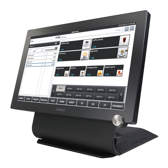
Casio V-R7000 Service Manual
Electronic cash register
Hide thumbs
Also See for V-R7000:
- User manual (36 pages) ,
- Programming and reference manual (155 pages) ,
- Reference manual (79 pages)

Related Manuals for Casio V-R7000


Summary of Contents for Casio V-R7000
- Page 1 SERVICE MANUAL ELECTRONIC CASH REGISTER V-R7000/V-R7100 (EX-870) JUL. 2014 Ver.3 : Mar. 2017...
-
Page 2: Precautions For Use
Precautions for Use Installation Location Do not place in a hot or dusty location, or in any location exposed to oily smoke or water. Never store or leave in following locations. This could erase the memory and cause a malfunction or result in deformation of the case. - Page 3 * Caution ! / Attention ! Battery • Risk of explosion if battery is replaced by an incorrect type. • Dispose of used batteries according to the instructions. Batterie • il y a danger d’explosion si la batterie est remplacée par une batterie de type incorrect. •...
-
Page 4: Table Of Contents
V-R7000/V-R7100 CONTENTS 1. SPECIFICATIONS ........... . 1 1-1. -
Page 5: Specifications
V-R7000/V-R7100 1. SPECIFICATIONS 1-1. Specifi cations List Display Type 15.6 inch WXGA color TFT liquid crystal display Resolution 1366 x 768 Backlight White LED Touch panel Method 4-wire resistive fi lm Size 15.6 inch Wireless LAN Standard IEEE 802.11a/b/g/n (V-R7100 only) -
Page 6: Part Names And Functions
V-R7000/V-R7100 1-2. Parts Names and Functions 1 Indicator Display the status of the power supply. Turn the power ON. It will display the shutdown menu when 2 Power switch pressed and held. Switch the ON and OFF of the screen display. -
Page 7: Option List
V-R7000/V-R7100 1-3. Option List DEVICE NAME MODEL SPECIFICATION NOTE Remote printer UP-400B EX-PRT-UNIT-10B Remote printer UP-370B EX-PRT-UNIT-11B Customer display (Black) VA-B60D EX-DP-UNIT-16E-BK Magnetic card reader unit VA-B46MCRE EX-MCR-PCG-15B Expansion interface box VA-B20EB EX-IO-UNIT-1A Drawer cable VA-B30CB EX-MDR-CB-4 Display cable for customer... -
Page 8: About Power Switches
V-R7000/V-R7100 1-5. About Power Switches V-R7000/V-R7100 has the following three switches for turning the power ON and OFF. Use these switches according to your requirements. Before removing the power plug, always shut down the main unit and turn the main power switch OFF. -
Page 9: Turning The Power Off (Shutdown)
V-R7000/V-R7100 1-7. Turning the Power OFF (shutdown) 1. Shut down the main unit. There are two ways to shut down the main unit. Using the OFF Switch (1) Press and hold the OFF switch for approximately 1 second. (2) Touch the “Power off” display. -
Page 10: Updating The Os
2-2. Updating Method Select “Settings” → “About tablet” → “System Update”. TIPS: Even if the model is V-R7100, the model No. shows “V-R7000”. Updating the OS from an SD card (1) Prepare an OS image fi le to be updated. - Page 11 (1) Prepare a FTP server or HTTP server to store the update fi le. (2) Create a “V-R7000” folder right under the prepared FTP or HTTP site, and store the OS image fi le and a fi le “V-R7000Update.xml” where the OS image fi le name is written.
-
Page 12: Hardware Test
V-R7000/V-R7100 3. HARDWARE TEST NOTE: When the Main PCB is replaced with a new one • Be sure to carry out ID registration (Test program → Device ID). • A OS software is installed in main board for spare parts. Please update appropriate OS software if necessary. -
Page 13: Operation Check
V-R7000/V-R7100 3-2. Operation Check Touch Panel Calibration Tap “Settings” “Touch Screen Calibration”. Operate according to the on-screen instructions. Forced Power OFF Operation Check Press the reset switch. Check that the backup battery does not operate and the power is forcedly turned OFF. - Page 14 V-R7000/V-R7100 Backup Battery Operation Check Check the remaining amount of the backup battery. If the backup battery icon is red, charge the Backup battery icon battery before proceeding to the following Steps. Tap “Settings” “Display” “Power Down Main power switch Pending”, and select “10 minutes”.
-
Page 15: Preparation Before Testing
V-R7000/V-R7100 3-3. Preparation Before Testing (1) Required tools and devices • Prepare required tools and devices referring to “3-1. List of Tests”. • About media NOTE: Format the media in FAT32 format. For safety, before removing the media, be sure to tap “Settings” “Storage”, and then TIPS: unmount it. -
Page 16: Testing Without Using The Test Application
V-R7000/V-R7100 3-4. Testing without Using the Test Application LAN Port Tap “Settings” set “Ethernet” to ON. Tap “eth0”, and check and record the network information of the terminal. Connect the LAN port and that of the access point with the LAN cable. -
Page 17: Test Application
V-R7000/V-R7100 3-5. Test Application Installing the Test Application Tap “Settings” “Security”, and check the “Unknownsources” box. Connect the USB Flash Drive (for Test tool) to the USB Port 1. Tap “Open Maneger”. USB Port 1 Tap “USB Storage 1” ... - Page 18 V-R7000/V-R7100 The test program runs. About the test program menus TIPS: Test items to be carried out and the testing order are arbitrary. Light gray Testing is impossible. Dark gray Untested Green Test result is OK. Orange Test result is NG.
- Page 19 V-R7000/V-R7100 TouchPanel Tap “TouchPanel”. On the screen, trace the following letters with your fi nger tip, for example. Tap “ ” to show the judgment screen, and then tap the obtained test result. Tap “LCD”. Check that the black screen and white screen will alternate each time you tap the screen.
- Page 20 V-R7000/V-R7100 mic/speaker Tap “mic speaker”. Record a voice and then play it back. Check that the recorded voice is properly played back. : Starts recording. : Stops recording. : Plays back. After checking the playback voice, tap “Discard” to terminate the test.
- Page 21 V-R7000/V-R7100 SD 2 (Left Side) Insert the SD card to the SD Slot 2. Tap “SD 2 (Left Side)”. Automatic judgment is done and the test result SD Slot 2 appears. Head set Connect a Head set. Tap “Head set”.
- Page 22 V-R7000/V-R7100 HDMI NOTE: Since the connector is located on the rear side, carefully connect or disconnect the cable. Connect a monitor with the HDMI input connector to the HDMI Port with the HDMI cable. HDMI Port Tap “HDMI”. Check that a video is displayed on the monitor together with a sound.
- Page 23 V-R7000/V-R7100 USB 1 (Back) NOTE: Since the port is located on the rear side, carefully insert or remove the USB fl ash drive. NOTE: Note that the USB numbers used in the test program and the device differ with each other.
- Page 24 V-R7000/V-R7100 Drawer 5 V NOTE: Since the connector is located on the rear side, carefully connect or disconnect the cable. Connect a drawer. Tap “Drawer 5V”. Tap “Drawer Open” “OK”. Drawer opens and the judgment result is indicated by the frame color of the “Drawer status open”.
- Page 25 V-R7000/V-R7100 TIPS: MCR model only Tap “MCR” “Other country”. After tapping “Japan”, slide the test magnetic card within approximately 3 seconds. Automatic judgment is done and the test result appears. OK: Green, NG: Red Tap “ ” to show the judgment screen, and then tap the obtained test result.
- Page 26 V-R7000/V-R7100 Device ID NOTE: When the Main PCB is replaced with a new one, be sure to perform this item. Tap “Device ID”. Read the Device ID with a scanner, or directly enter the Device ID. NOTE: The ports for the USB scanner are USB Port 2 to USB Port 4 located on the rear side.
-
Page 27: Other Testing
V-R7000/V-R7100 3-6. Other Testing Bluetooth Test TIPS: V-R7100 only Launch the “Settings” app. Turn ON “Bluetooth”. Check that the device may be paired with the Bluetooth device you have. Wi-Fi Test TIPS: V-R7100 only Launch the “Settings” app. Turn ON “Wi-Fi” and set the access point and the connection settings. -
Page 28: Hardware
V-R7000/V-R7100 4. HARDWARE 4-1. BLOCK DIAGRAM Cable E870 MCR PCB E870 B-CONTACT PCB Sub Battery IButton E870 LED PCB WiFi Main power switch 5 GHz 2.4 GHz Power switch E870 IOC PCB E870 MAIN PCB BOOT switch Drawer Drawer OFF switch... -
Page 29: Pcb Layout
V-R7000/V-R7100 4-2. PCB Layout E870 MAIN PCB – 25 –... - Page 30 V-R7000/V-R7100 E870 IOC PCB E870 COM PCB E870 LED PCB E870 B-CONTACT PCB E870 MIC PCB E870 MCR PCB – 26 –...
-
Page 31: Disassembly
V-R7000/V-R7100 5. DISASSEMBLY 5-1. Important • Please note that the product on this manual may appear to be different from the actual one according to the changes such as engineering design change. • In order to prevent static and avoid leaving grease from the hand, wear conductive gloves, fi... - Page 32 • Remove the main unit from the stand or VESA stand by reversing the installation order referring to "V-R7000/V-R7100 Installation Manual". • When replacing the MCR, refer to “V-R7000/V-R7100 Installation Manual”. • The disassembly procedure explained here is based on the model “V-R7100-BD”...
-
Page 33: Flowchart
V-R7000/V-R7100 5-2. Flowchart B-CASE-ASSY BACK-CHASSIS-ASSY [Main components] PCB UNIT/MAIN PCB UNIT/MCR PCB UNIT/COM PCB-CHASSIS-ASSY PCB UNIT/IOC [Main components] LCD ASSY FRONT-CASE-ASSY [Main components] – 29 –... -
Page 34: Procedure
V-R7000/V-R7100 5-3. Procedure A. B-CASE-ASSY A-1. Remove the COVER/MCR and COVER/IF. A-2. Peel off two BLIND/SCREW. NOTE: Carefully peel off so as not to give damage to the case. A-3. Undo six screws. NOTE: Two kinds of screws are used. (S1 × 4, S2 × 2) - Page 35 V-R7000/V-R7100 NOTE: Since the BATTERY ASSY is installed, do not let its plus terminal contact the chassis. Doing so can cause a short circuit and the BATTERY ASSY is damaged. Plus terminal BATTERY ASSY A-5. The parts confi guration of the B-CASE-ASSY is as follows.
- Page 36 V-R7000/V-R7100 B. BACK-CHASSIS-ASSY B-1. Disconect one connector. B-2. Disconect two coaxial connectors of the antenna. (V-R7100 only) B-3. Peel off one tape that fi xes the coaxial cable of the Wireless LAN antenna. (V-R7100 only) B-4. Undo six screws. B-5. Remove the BACK-CHASSIS-ASSY.
- Page 37 V-R7000/V-R7100 Note on reassembling Marking When fastening the screw, use the hole with a mark. Tape Run the antenna cable (black) and fi x it with one tape. – 33 –...
- Page 38 V-R7000/V-R7100 Replacement of BATTERY ASSY NOTE: When the sub battery is replaced with a new one, be sure to perform the test item “Backup Battery Operation Check”. (1) Peel off two tapes. (2) Undo one screw. (3) Remove the PCB UNIT/TERMINAL.
- Page 39 V-R7000/V-R7100 C. PCB UNIT/MAIN NOTE: Two wireless LAN antenna cables are attached with a new PCB UNIT/MAIN for V-R7100. Replace the current antenna cables with new ones as required. C-1. Disconnect three connectors. C-2. Undo four screws. C-3. Remove the PCB UNIT/MAIN by sliding it sideways.
- Page 40 V-R7000/V-R7100 • Do not mix up the connectors for the speaker and the microphone. Speaker (Lead wires: red, black) Microphone (Lead wires: red, white) A black dot is marked on the PCB side connector. D. PCB UNIT/IOC NOTE: The PCB UNIT/IOC cannot be removed if the PCB UNIT/MAIN is not removed yet.
- Page 41 V-R7000/V-R7100 E. PCB UNIT/MCR E-1. Undo one screw. E-2. Disconnect one connector. Screw (S3) PCB UNIT/MCR F. PCB UNIT/COM F-1. Disconnect one FFC. F-2. Undo two screws and remove the PLATE/SUB. F-3. Undo six lock screws and remove the PCB UNIT/COM.
- Page 42 V-R7000/V-R7100 G. PCB CHASSIS ASSY NOTE: The PCB CHASSIS ASSY cannot be removed if the PCB UNIT/MAIN is not removed yet. G-1. Peel off one tape, release the connector lock, and disconnect the FPC. G-2. Peel off one tape. G-3. Remove two antennas (silver parts). (V-R7100 only) G-4.
- Page 43 V-R7000/V-R7100 Note on reassembling Note on the wireless LAN model • Do not assemble the PCB CHASSIS ASSY with the silver part of the antenna stuck to the LCD. Check points Positioning places Three cables pass through the hole in the PCB CHASSIS ASSY.
- Page 44 V-R7000/V-R7100 • SPEAKER Fix with one tape. Screw (S6) Tape SPEAKER • Cable (CABLE/MCR) Fix with one tape. CABLE/MCR Tape • FFC (CABLE/FFC/IOC) CABLE/FFC/IOC When replaced with a new one, fold it as shown below. E870-IOC E870-COM Reinforcing plate 45 mm...
- Page 45 V-R7000/V-R7100 H. LCD ASSY H-1. Remove the LCD ASSY. H-2. The parts confi guration of the LCD ASSY is as follows. CABLE/LCD CABLE/LCD/BL PLATE/LCD/R PLATE/LCD/L LCD ASSY CUSHION/LCD/V CUSHION/LCD/H CUSHION/LCD/V Note on reassembling • Be sure that no dust or dirt is on the touch panel and LCD surfaces.
- Page 46 V-R7000/V-R7100 I. FRONT-CASE-ASSY I-1. The parts confi guration of the FRONT-CASE-ASSY is as follows. FRONT-CASE-ASSY * Including Touch Panel Dallas key model only SPACER/DALLAS DALLAS ASSY FERRITE CORE CABLE/MIC CABLE/LED PCB UNIT/LED LENS/LED PCB UNIT/MIC FG/PLATE/MIC BUTTON/POWER TAPE/BUTTON CUSHION/BUTTON Note on replacing the CASE ASSY/FRONT of the wireless LAN model •...
-
Page 47: Exploded View/Parts List
3. The numbers in item column correspond to the same numbers in drawing. 4. CASIO does not supply the spare parts without parts code. 5. Refer to the latest “Parts Price Code” at “PARTS FINDER” on the Casio Service WEB site (https://www.servicecasio.com). -
Page 48: Exploded View
V-R7000/V-R7100 6-1. Exploded View STAND-ASSY B-CASE-ASSY Dallas type 3-19 BACK-CHASSIS-ASSY 3-18 3-20 DRAWER DRAWER DC IN PORT 2 PORT 1 COM1 3-21 HDMI COM2 ( + 5 V) COM3 ( + 5 V) Dallas type 3-22 3-23 3-24 3-14 3-16... -
Page 49: Parts List
V-R7000/V-R7100 6-2. Parts List 1 V-R7000-BD 2 V-R7100-BD 3 V-R7000-U 4 V-R7100-U 5 V-R7000-C 6 V-R7100-C Q'TY Item Code No. Parts Name Specification Remarks 1. GENERAL-ASSY 10476831 COVER/JACK/BK RJE504254-001V01 10476832 BUTTON/OFF/BK RJE504261-001V01 10476833 COVER/DP-SW/BK RJE504251-001V01 10476880 COVER/MCR/BK RJE504260-001V01 10478538 BLIND/SCREW/BK... - Page 50 V-R7000/V-R7100 1 V-R7000-BD 2 V-R7100-BD 3 V-R7000-U 4 V-R7100-U 5 V-R7000-C 6 V-R7100-C Q'TY Item Code No. Parts Name Specification Remarks 3-10 10476872 BUTTON/POWER/BK RJE504255-001V01 3-11 10476874 TAPE/BUTTON RJE504292-001V01 3-12 10476873 CUSHION/BUTTON RJE504291-001V01 3-13 10485322 PCB UNIT/LED TK-RJE504271*001 3-14 10476877...
- Page 51 V-R7000/V-R7100 1 V-R7000-BD 2 V-R7100-BD 3 V-R7000-U 4 V-R7100-U 5 V-R7000-C 6 V-R7100-C NOTE: When the IOC PCB is replaced with a new one • Be sure to carry out UUID registration (Test program → Reg UUID). – 47 –...
-
Page 52: Drawer M-Type (Dl-2436/2814/2815)
V-R7000/V-R7100 6-3. Drawer M-type (DL-2436/2814/2815) Exploded View Bottom View DL-2436 DL-2814/2815 – 48 –... - Page 53 V-R7000/V-R7100 Parts List 1 DL-2814 2 DL-2815 3 DL-2436 Qt'y Item Code No. Parts Name Specification 10203171 RUBBER/FOOT CASE RJE500667-001V02 10167366 RUBBER/FOOT RJE501204-001V01 10230100 CABLE/FG RJE500104*001V03 10408590 METAL/TRAP RJE503885-001V01 10378459 ROLLER/DELRIN PB-19B1 52000106 RIVET 5X30 10203374 LOCK/CYLINDER CL-23 10292500 PANEL/FRONT...
-
Page 54: Drawer L-Type (Dl-3401)
V-R7000/V-R7100 6-4. Drawer L-type (DL-3401) Exploded View 23 S7 – 50 –... - Page 55 V-R7000/V-R7100 Parts List 1 DL-3401 Qt'y Item Code No. Parts Name Specification CASE/MAIN V012K00008 9487 0975 LOCK SUB ASSY V081K00013-K1 9487 0976 SOLENOID SUB ASSY ZD53541 1907 7123 SPRING/PUSH ZD01370B 1907 6277 RUBBER/DAMPER V044E00002K1 1906 0674 CABLE ASSY ZD53544-K3 NYLON CLAMP...
-
Page 56: Drawer L-Type (Dl-3624/3625)
V-R7000/V-R7100 6-5. Drawer L-type (DL-3624/3625) Exploded View – 52 –... - Page 57 V-R7000/V-R7100 Parts List 1 DL-3624 2 DL-3625 Qt'y Item Code No. Parts Name Specification 1041 4326 LOCK ASSY V081K00034K1 1041 4327 LOCK ASSY V081K00035K1 1907 9613 WIRE/FG ZD31670 CLAMP CKN-5 1902 7112 GROMMET 1902 7076 SPRING/PUSH ZD01370B 1902 6829 RUBBER/DAMPER...
- Page 58 Ver.3 : Mar. 2017 • Correction of the HARDWARE TEST (P11) • Correction of the EXPLODED VIEW (P44) • Correction of the PARTS LIST (P47) CASIO COMPUTER CO., LTD. CS Technical Department TOKYO, JAPAN © 2014-2017 CASIO COMPUTER CO., LTD.