Panasonic EY7549 Service Manual
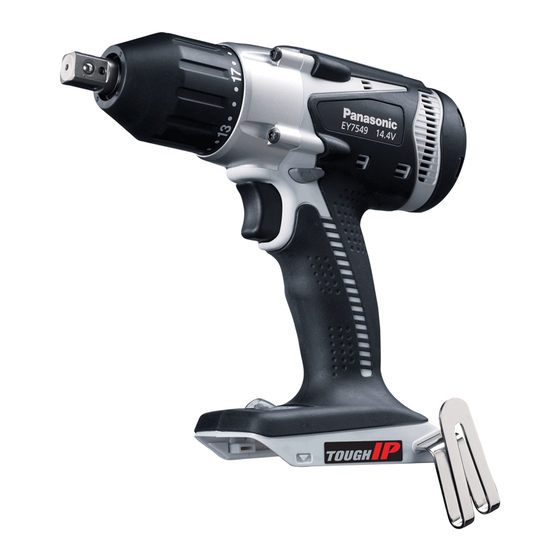
Cordless multi- impact & drill driver
Hide thumbs
Also See for EY7549:
- Operating instructions manual (58 pages) ,
- Operating instructions manual (140 pages)
Advertisement
Quick Links
TABLE OF CONTENTS
1 Warning -------------------------------------------------------------- 2
2 Specifications ----------------------------------------------------- 2
3 Troubleshooting Guide ----------------------------------------- 3
4 Disassembly and Assembly Instructions ---------------- 8
5 Wiring Connection Diagram ---------------------------------15
6 Schematic Diagram ---------------------------------------------15
7 Exploded View and Replacement Parts List -----------16
Cordless Multi- Impact & Drill Driver
Model No.
Europe
Oceania
PAGE
© Panasonic Eco Solutions Power Tools Co., Ltd.
2013. All rights reserved. Unauthorized copying and
distribution is a violation of law.
Order Number PTD1301X19CE
EY7549
PAGE
Advertisement

Related Manuals for Panasonic EY7549


Summary of Contents for Panasonic EY7549
-
Page 1: Table Of Contents
4 Disassembly and Assembly Instructions ---------------- 8 5 Wiring Connection Diagram ---------------------------------15 6 Schematic Diagram ---------------------------------------------15 7 Exploded View and Replacement Parts List -----------16 © Panasonic Eco Solutions Power Tools Co., Ltd. 2013. All rights reserved. Unauthorized copying and distribution is a violation of law. -
Page 2: Warning
1 Warning Caution: • Pb free solder has a higher melting point that standard solder; Typically the melting point is 50 - 70°F (30 - 40°C) higher. Please use a soldering iron with temperature control and adjust it to 750 ± 20°F (400 ± 10°C). In case of using high temperature solder- ing iron, please be careful not to heat too long. -
Page 3: Troubleshooting Guide
3 Troubleshooting Guide 3.1. Troubleshooting Guide... - Page 7 3.2. Trial Operation (After Checking Troubleshooting Guide) 3.2.1. Assembly • Confirm if there is no gap between housing A and B by pinching lead wires. • Confirm all screws are tightened firmly. 3.2.2. Operation • Check whether the tool operates properly in both the forward and reveres directions. •...
-
Page 8: Disassembly And Assembly Instructions
4 Disassembly and Assembly Instructions *To assemble the tool, start with 4-12 and proceed to 4-1 4.1. Removing the plate hook 4.2. Removing the Fixation cover assembly... - Page 9 4.3. Removing the housing 4.4. Removing the switch assembly...
- Page 10 4.5. Removing the Module assembly...
- Page 11 4.6. Removing the Driving assembly and Motor assembly 4.7. Removing the Carbon brush block...
- Page 12 4.8. How to attach the D/I change handle and L/H change handle...
- Page 13 4.9. Tips for installing the driving cover assembly onto the driving assembly...
- Page 14 4.10. Wiring and Assembly Points...
-
Page 15: Wiring Connection Diagram
5 Wiring Connection Diagram 6 Schematic Diagram... -
Page 16: Exploded View And Replacement Parts List
7 Exploded View and Replacement Parts List Model No. : EY7549 Exploded View... - Page 17 Model No. : EY7549 Parts List Ref. Safety Part No. Part Name & Description Q'ty Remarks WEY7549H7029 HOUSING AB SET 1 (for EUROPE) WEY7549H7020 HOUSING AB SET 1 (for OCEANIA) WEY7549K4058 FIXATION COVER ASSEMBLY WEY7548S0277 FIXATION COVER WEY7549K9038 TORX TAPPING SCREW...