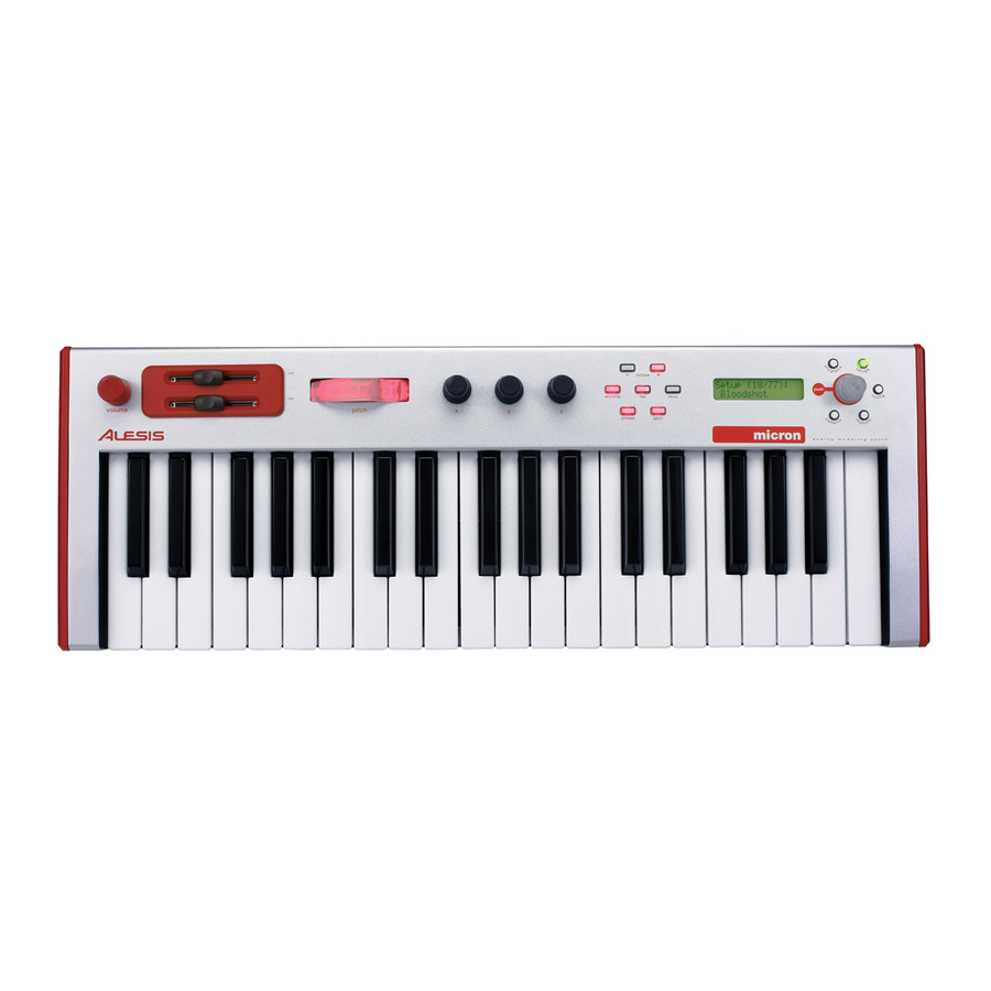
Alesis Micron Service Manual
Analog modeling synth
Hide thumbs
Also See for Micron:
- Reference manual (133 pages) ,
- Quick start owner's manual (33 pages) ,
- Programming chart (9 pages)
Advertisement
Table of Contents
- 1 Safety Instructions
- 2 Specifications
- 3 Control Knob Circle
- 4 Key Concepts
- 5 Navigating with the Transparent Control Knob and Its Buttons
- 6 Disassembly Procedures
- 7 Wiring Diagram
- 8 Packing Diagram
- 9 Explode Diagram
- 10 Visual Inspection
- 11 External Audio Input
- 12 Automated Tests
- 13 Firmware Update
- Download this manual
MICRON (Q02)
Service Manual
THIS DOCUMENT CONTAINS SENSITIVE
PROPRIETARY INFORMATION.
ALL RECIPIENTS MUST HAVE A CURRENT
NON-DISCLOSURE AGREEMENT ON FILE
COPIES OF THIS DOCUMENT
The information in this document contains privileged and confidential information.
It is intended only for the use of those authorized by Alesis. If you are not the
authorized, intended recipient, you are hereby notified that any review,
dissemination, distribution or duplication of this document is strictly prohibited. If
you are not authorized, please contact Alesis and destroy all copies of this
document. You may contact Alesis at servicemanuals@alesis.com or at
support@alesis.com.
Copyright © 2004 Alesis, LLC
Confidential
ALESIS
P/N: 8-31-0147-A
ATTENTION!
WITH ALESIS, LLC.
DO NOT MAKE ILLEGAL
Alesis Service Manual
8-31-0147-A
Advertisement
Table of Contents

Related Manuals for Alesis Micron


Summary of Contents for Alesis Micron
- Page 1 COPIES OF THIS DOCUMENT The information in this document contains privileged and confidential information. It is intended only for the use of those authorized by Alesis. If you are not the authorized, intended recipient, you are hereby notified that any review, dissemination, distribution or duplication of this document is strictly prohibited.
- Page 2 Your purchase of the Manual shall be for your own ultimate use and shall not be for purposes of resale or other transfer. As the owner of the copyright to the Manual, Alesis does not give you the right to copy the Manual, and you agree not to copy the Manual without the written authorization of Alesis. Alesis has no obligation to provide to you any correction of, or supplement to, the Manual, or any new or superseding version thereof.
- Page 3 ALL REPAIRS DONE BY ANY ENTITY OTHER THAN AN AUTHORIZED ALESIS SERVICE CENTER SHALL BE SOLELY THE RESPONSIBILITY OF THAT ENTITY, AND ALESIS SHALL HAVE NO LIABILITY TO THAT ENTITY OR TO ANY OTHER PARTY FOR ANY REPAIRS BY THAT ENTITY.
-
Page 4: Safety Instructions
The product is exposed to water or excessive moisture, c. The AC power supply plug or cord is damaged, d. The product shows an inappropriate change in performance or does not operate normally, or e. The enclosure of the product has been damaged. Confidential Alesis Service Manual 8-31-0147-A... -
Page 5: Specifications
8.25 lbs / 3.5 kg Effects: 4 Drive Effects (1 each per Part) plus Master Effects (Shared) Volume The (volume) knob on the far left-hand side of the Micron Audio Input raises and lowers Input Connectors: 2 Balanced 1/4” TRS jacks the volume. - Page 6 ALESIS MICRON (Q02) COMPONENTS Confidential Alesis Service Manual 8-31-0147-A...
-
Page 7: Control Knob Circle
Pressing one of these buttons – [programs], [setups], [config], [patterns], or [rhythms] – puts you into one of the Micron’s primary modes of operation. Turning the control knob then cycles through options. Pressing the control knob allows for editing. -
Page 8: Disassembly Procedures
DISASSEMBLY PROCEDURES 1. REMOVAL OF TOP AND BOTTOM PANEL (Fig.1) (A) TAKE OUT THE 8 PCS SCREW FIXING THE KEYBED FROM WHICH THE BOTTOM CHASSIS (B) TAKE OUT THE 7 PCS NUT OF 1/4”CONNECTORS FROM TOP PANEL (C) TAKE OUT THE 16 PCS SCREW FROM WHICH THE BOTTOM PANEL (Fig.1) 2. - Page 9 3. REMOVAL OF ASSY PCB (Fig.3) REMOVAL THE 3 PCS SCREW FROM THE TOP PANEL RIGHT PCB REMOVAL THE 4 PCS SCREW FROM THE LCD PCB REMOVAL THE 6 PCS SCREW FROM THE TOP PANEL CENTER PCB REMOVAL THE 4 PCS SCREW FROM THE TOP PANEL LEFT PCB REMOVAL THE 2 PCS SCREW FROM THE ASSY PITCH WHEEL (Fig.3)
-
Page 10: Wiring Diagram
WIRING DIAGRAM (US/EU/UK/AUS NZ) -
Page 11: Packing Diagram
PACKING DIAGRAM (US/EU/UK/AUS NZ) -
Page 12: Explode Diagram
EXPLODE DIAGRAM (US/EU/UK/AUS NZ) SEQUENCIAL NO OF EXPLODE DIAGRAM WILL BE MARKED ON REF. COLUMM OF BOM LIST... - Page 13 ALESIS MICRON (Q02) Confidential Alesis Service Manual 8-31-0147-A...
- Page 14 Q02 BOM DESCRIPTION LEVEL PT130442401 FIXED HOLDER MT1304449 FIXED METAL SC0308RBZI SCREW 19 3 SC0306RICI SCREW 23 4 9-15-0307 END CAP LEFT 7-10-0122 KEYBED 37 KEYS PT133030401 BOTTOM CHASSIS SC0310RBZI SCREW SC3506AICI SCREW 16 13 BAAR-034 PU STAND LAC22ALE27 STICKER BARCODE S/N PT131067101 CAP FADER PT130442301...
- Page 15 Q02 BOM DESCRIPTION LEVEL PITCH MOD轉輪 9-15-0301 TWPC04A02001 FRONT PANEL PCB ASS'Y PC04A020 FRONT PANEL PCB TWPC04A020A01 FRONT PANEL PCB ASS'Y CN0420002002 4P CONNECTOR (200mm) CN2625401301 26P CONNECTOR (130mm) PC04A020A FRONT PANEL PCB TE622000302 3P CONNECTOR (J6) TE812000411 4P CONNECTOR (J5) 0-09-0044 VR 2.5KB...
- Page 16 Q02 BOM DESCRIPTION LEVEL TE10200601 6P CONNECTOR TE612000202 2P CONNECTOR J11,16 WS073307IC WASHER (U3) 0-05-1399 RESISTOR 3.9O R91,92 0-16-2210 RESISTOR 221O (SMD)1% 10 R4,9,10,46,47,65,71,79,80,83 0-16-3650 RESISTOR 365O (SMD)1% 0-17-0103 RESISTOR 4×10K 1/16W R7,8,16,33,34,56,64,70 0-17-0221 RESISTOR 4×220O 1/16W R49,57~63 0-17-0470 RESISTOR 4×47O 1/16W R6,85,86,90 1-08-0222 ELECT 22UF/16V...
- Page 17 ALESIS MICRON (Q02) QC PROCEDURES Confidential Alesis Service Manual 8-31-0147-A...
-
Page 18: Visual Inspection
Q02 QC Test Procedures Items required for test (one each unless otherwise specified): • Q02 unit with current OS • 9VAC, 1.5A power adapter • MIDI cable • Sustain pedal • Pair of headphones • AP Computer w/ cables Setup 1) Connect power adapter to power outlet and to Q02. -
Page 19: External Audio Input
Audio Output Test 1) While listening to the headphones, press a key and turn the Master Volume knob clockwise until the sound is at a comfortable listening level (this verifies that the Master Volume pot is functional). Verify that both the left and right sides of the headphones produce a sound. -
Page 20: Automated Tests
AP Test 1) Unplug the headphones from the Q02 headphones jack. 2) Turn the Master Volume knob completely clockwise. 3) Connect the AP generator outputs A and B to the Q02 audio in left and right, respectively. 4) Connect the Q02 main output left and right to the AP analyzer inputs A and B, respectively. - Page 21 Press all keys. 1) Verify that the first line of the LCD says “Press all keys”. 2) When a key pressed, verify that the LCD says “Key ## down”, where ## is the key number. The leftmost key is number 0, and the rightmost key is number 36.
- Page 22 Turn knob x --> 1) Verify that the first line of the LCD says “Turn knob x -->”. 2) Turn knob x to the right until the number passes 1500. 3) Verify that the turning is smooth. If the number jumps around, the unit does not pass.
-
Page 23: Firmware Update
Push sus pedal. 1) Verify that the first line of the LCD says “Push sus pedal”.. 2) Verify that the sustain pedal is plugged into the sustain jack, and push and release the sustain pedal. Push: MIDI loop. 1) Verify that the first line of the LCD says “Push: MIDI loop”. 2) Verify that the MIDI in jack is connected to the MIDI out jack with a MIDI cable. - Page 24 ALESIS MICRON (Q02) SCHEMATIC FILES Confidential Alesis Service Manual 8-31-0147-A...
- Page 41 ALESIS MICRON (Q02) HISTORY Confidential Alesis Service Manual 8-31-0147-A...