Table of Contents
Advertisement
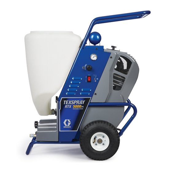
Operation, Parts
RTX5000 & RTX5500
Texture Sprayers
For water-Based Materials Only.
Models: RTX5000PI, RTX5000PX, RTX5500PI & RTX5500PX
100 psi (6.9 bar, 0.69 MPa) Maximum Working Pressure
Important Safety Instructions
Read all warnings and instructions in this manual and related manuals.
Be familiar with the controls and the proper usage of the equipment.
Save these instructions.
Related Manuals
Gun – 3A3373
Use only genuine Graco replacement parts.
The use of non-Graco replacement parts may void warranty.
3A3265A
ti27921a
EN
Advertisement
Table of Contents

Related Manuals for Graco RTX5000


Summary of Contents for Graco RTX5000
-
Page 1: Important Safety Instructions
Read all warnings and instructions in this manual and related manuals. Be familiar with the controls and the proper usage of the equipment. Save these instructions. Related Manuals Gun – 3A3373 ti27921a Use only genuine Graco replacement parts. The use of non-Graco replacement parts may void warranty. -
Page 2: Table Of Contents
RTX5000, RTX5500 Sprayer Parts ........ -
Page 2: Table Of Contents
RTX5000, RTX5500 Sprayer Parts List ........27... -
Page 3: Models
Models Models Model RTX5000pi 17H575 RTX5000pi Rental 17H576 RTX5000pi Rental HD 17K302 RTX5000px 17H579 RTX5000pi 17L288 RTX5000pi Rental 17L289 RTX5000px 17L292 110474 Certified to RTX5500px 17H581 CAN/CSA C22.2 No. 68 Conforms to UL 1450 RTX5500pi 17H577 230 Europe Multi RTX5500px 17H580 RTX5500pi 17H578... -
Page 3: Models
Models Models Model RTX5000pi 17H575 RTX5000pi Rental 17H576 RTX5000pi Rental HD 17K302 RTX5000px 17H579 RTX5500px 17H581 RTX5000pi 17L288 RTX5000pi Rental 17L289 110474 Certified to RTX5000px 17L292 CAN/CSA C22.2 No. 68 Conforms to UL 1450 RTX5500pi 17H577 230 Europe Multi RTX5500px 17H580 RTX5500pi 17H578... -
Page 4: Warnings
Warnings Warnings The following warnings are for the setup, use, grounding, maintenance, and repair of this equipment. The exclamation point symbol alerts you to a general warning and the hazard symbols refer to procedure-specific risks. When these symbols appear in the body of this manual or on warning labels, refer back to these Warnings. -
Page 4: Warnings
Warnings Warnings The following warnings are for the setup, use, grounding, maintenance, and repair of this equipment. The exclamation point symbol alerts you to a general warning and the hazard symbols refer to procedure-specific risks. When these symbols appear in the body of this manual or on warning labels, refer back to these Warnings. - Page 5 Do not kink or over-bend the material or air hose. • Do not expose the hose to temperatures or to pressures in excess of those specified by Graco. • Do not use the hose as a strength member to pull or lift the equipment.
- Page 5 Do not kink or over-bend the material or air hose. • Do not expose the hose to temperatures or to pressures in excess of those specified by Graco. • Do not use the hose as a strength member to pull or lift the equipment.
- Page 6 Warnings PRESSURIZED EQUIPMENT HAZARD Fluid from the equipment, leaks, or ruptured components can splash in the eyes or on skin and cause serious injury. • Follow the Pressure Relief Procedure when you stop spraying/dispensing and before cleaning, checking, or servicing equipment. •...
- Page 6 Warnings PRESSURIZED EQUIPMENT HAZARD Fluid from the equipment, leaks, or ruptured components can splash in the eyes or on skin and cause serious injury. • Follow the Pressure Relief Procedure when you stop spraying/dispensing and before cleaning, checking, or servicing equipment. •...
-
Page 7: Component Identification
Component Identification Component Identification ti27922a Gun Nozzle ON/OFF Switch Tool Box Burp Guard Material Hopper Prime Valve Hopper Connect/Disconnect Power Cord RotoFlex™ II Pump Hose - 25-ft (7.6 m) Pump Hose Outlet Material Thickness Gauge Handle Cleaning (Sponge) Ball Air Hose Outlet ProGuard Auxiliary Air Hose Inlet (px models Air control valve... -
Page 8: Preparation
Preparation Preparation Grounding Pressure Relief Procedure Follow the Pressure Relief The equipment must be grounded to Procedure whenever you see this reduce the risk of static sparking and symbol. electric shock. An electric or static spark can cause fumes to ignite or explode. An improper ground can cause electric shock. -
Page 9: Softstart/Smart Start System
Preparation Hose Size and Length Soft Start The Soft Start System is controlled by motor The system comes with a 25 ft (7.6m) long power and an air cylinder. When pressurized, hose set consisting of a material hose 1 in. or the air cylinder pushes the rollers into the 1.25 in. -
Page 10: Setup
Setup Setup Install spray nozzle. See Recommended Nozzle & Disc Selection Charts, page 15. Pulling trigger when installing nozzle makes assembly easier. NOTICE • Do not store sprayer under pressure. • Do not allow material to dry inside pump, hoses, gun or spray system. This may cause pump to fail. -
Page 11: Material Hopper
Setup Material Hopper Mixing Material Install Hopper Position hopper outlet over fitting as far as it will go. NOTE: Correct material mixture is essential. The pump will not operate if the mixture is too thick. Use water-based materials only. • Mix the material in a separate container before pouring it into hopper. -
Page 11: Material Hopper
Setup Material Hopper Mixing Material Install Hopper Position hopper outlet over fitting as far as it will go. NOTE: Correct material mixture is essential. The pump will not operate if the mixture is too thick. Use water-based materials only. • Mix the material in a separate container before pouring it into hopper. - Page 12 Setup Premix Allow ceiling texture to set for at least 15 minutes. Then remix prior to use. Slowly add approximately 2 to 4 quarts (1.9 to 3.8 liters) of water to a 5 gallon After texture material is thoroughly (18.9 liter) bucket of premix. mixed, gently set ball end of Material Thickness Gauge on surface of mixture.
- Page 12 Setup Premix Allow ceiling texture to set for at least 15 minutes. Then remix prior to use. Slowly add approximately 2 to 4 quarts (1.9 to 3.8 liters) of water to a 5 gallon After texture material is thoroughly (18.9 liter) bucket of premix. mixed, gently set ball end of Material Thickness Gauge on surface of mixture.
-
Page 13: Operation
Operation Operation For the best spraying experience always Trigger gun into waste pail until hopper follow the Setup and Operation process. This no longer contains water and all water is ensures that the material and sprayer are removed from hose and pump system. ready to spray resulting in a successful project. -
Page 14: Texture Spraying
Operation Alternate Method (Using Prime Valve) Use this method when air flow with material through gun is not desired Air hose fittings can get hot. Allow sprayer to cool down 15 minutes before removing Turn ON/OFF switch to ON position. air hose. -
Page 14: Texture Spraying
Operation Alternate Method (Using Prime Valve) Use this method when air flow with material through gun is not desired Air hose fittings can get hot. Allow sprayer to cool down 15 minutes before removing Turn ON/OFF switch to ON position. air hose. -
Page 15: Recommended Nozzle & Disc Selection Charts
Operation Follow Mixing Material, page 11. To achieve uniform spray pattern, adjust air control valve and flow adjustment nut Trigger gun into a pail. When texture on gun. If you do not achieve the desired material appears at nozzle, move gun to pattern, change nozzles, see hopper and circulate until there is a solid Recommended Nozzle &... -
Page 16: Adjusting The System
Operation Adjusting the System For Less Material Flow Try one or a combination of these methods: Sufficient fluid output (volume and pressure) and good atomization is a balance of • Open air control valve. atomizing air, material thickness/material • Turn gun flow adjustment nut to flow and nozzle selection. -
Page 16: Adjusting The System
Operation Adjusting the System For Less Material Flow Try one or a combination of these methods: Sufficient fluid output (volume and pressure) and good atomization is a balance of • Open air control valve. atomizing air, material thickness/material • Turn gun flow adjustment nut to flow and nozzle selection. - Page 17 Operation Smart Start/Soft Start Operation ProGuard This sprayer protects itself against high and Smart Start low voltage. If the sprayer is plugged into a power source that is too low or too high the Sprayer will start under the following sprayer will stop operating.
- Page 17 Operation Smart Start/Soft Start Operation ProGuard This sprayer protects itself against high and Smart Start low voltage. If the sprayer is plugged into a power source that is too low or too high the Sprayer will start under the following sprayer will stop operating.
-
Page 18: Shutdown And Cleanup
Shutdown and Cleanup Shutdown and Cleanup NOTE: Keep pump and hose clean when switching between materials. A dirty pump can release particles of texture into the finish. • To increase pump life, life turn ON/OFF ti27968a switch OFF when not spraying. •... -
Page 18: Shutdown And Cleanup
Shutdown and Cleanup Shutdown and Cleanup NOTE: Keep pump and hose clean when switching between materials. A dirty pump can release particles of texture into the finish. • To increase pump life, life turn ON/OFF switch OFF when not spraying. ti27968a •... -
Page 19: Gun
Shutdown and Cleanup 16. Open gun air control valve. Perform Lift material hopper straight up, off the Pressure Relief Procedure, page 8. unit. 17. Finish cleaning all components. Be sure Plug opening on bottom of material to keep air passages in needle clean and hopper with your hand. -
Page 20: Maintenance
Maintenance Maintenance Routine maintenance is important to ensure proper operation of your sprayer. Maintenance includes performing routine actions which keep your sprayer in operation and prevent trouble in the future. Component Task Interval Sprayer Inspect motor shield vents for Daily or each time you spray blockage. -
Page 21: Troubleshooting
Refer to Grounding and Electrical Requirements, page 8. Gun needle plugged Clean needle and retry. Worn compressor Replace compressor. Contact a qualified Graco Service Center. Loose belt Tighten belt by adjusting com- pressor Broken belt Replace belt Lines not connected Check all quick disconnect connections to gun and hoses. -
Page 21: Troubleshooting
Refer to Grounding and Electrical Requirements, page 8. Gun needle plugged Clean needle and retry. Worn compressor Replace compressor. Contact a qualified Graco Service Center. Loose belt Tighten belt by adjusting com- pressor Broken belt Replace belt Lines not connected Check all quick disconnect connections to gun and hoses. - Page 22 Motor or control is damaged Take sprayer to Graco cycle. authorized service center. Electric outlet is not providing Try a different outlet or plug in power.
- Page 22 Motor or control is damaged Take sprayer to Graco cycle. authorized service center. Electric outlet is not providing Try a different outlet or plug in power.
- Page 23 If material is hardened in sprayer, pump or pressure switch may need to be replaced. Take sprayer to Graco authorized service center. Prime valve is plugged Remove and clean prime valve. Gun is plugged.
- Page 23 If material is hardened in sprayer, pump or pressure switch may need to be replaced. Take sprayer to Graco authorized service center. Prime valve is plugged Remove and clean prime valve. Gun is plugged.
-
Page 24: Rtx5000, Rtx5500 Sprayer Parts
RTX5000, RTX5500 Sprayer Parts RTX5000, RTX5500 Sprayer Parts Ref. Torque Hand tighten 50-70 in-lb (5.7 - 7.9 N•m) See page 29. ti27972a 3A3265A... -
Page 24: Rtx5000, Rtx5500 Sprayer Parts
RTX5000, RTX5500 Sprayer Parts RTX5000, RTX5500 Sprayer Parts Ref. Torque Hand tighten 50-70 in-lb (5.7 - 7.9 N•m) See page 29. ti27972a 3A3265B... -
Page 25: Rtx5000, Rtx5500 Sprayer (Continued)
RTX5000, RTX5500 Sprayer Parts RTX5000, RTX5500 Sprayer (continued) Ref. Torque Ref. Torque Ref. Torque 10-14.5 ft-lb (13.5 - 19.7 9-11 in-lb (1 - 1.2 N•m) 50-70 in-lb (5.7 - 7.9 N•m) N•m) Hand tighten 40-45 in-lb (4.5 - 5.1 N•m) 27-32 in-lb (3.1 - 3.6 N•m) -
Page 26: Rtx5000, Rtx5500 Sprayer (Continued)
RTX5000, RTX5500 Sprayer Parts RTX5000, RTX5500 Sprayer (continued) Ref. Torque Ref. Torque Ref. Torque 37.5-42.5 ft-lb 200-230 in-lb 40-45 in-lb (4.5 - 5.1 N•m) (51 - 57.6 N•m) (22.6 - 26 N•m) 15-20 in-lb (1.1 - 2.3 N•m) 9-11 in-lb (1.0 - 1.2 N•m) 27-32 in-lb (3.1 - 3.6 N•m) -
Page 27: Rtx5000, Rtx5500 Sprayer Parts List
RTX5000, RTX5500 Sprayer Parts RTX5000, RTX5500 Sprayer Parts List Ref. Part Description Qty. Ref. Part Description Qty. 16V095 SCREW, machine, 24S149 KIT, repair, compressor self-tapping includes 31, 77, 119, 24S148 KIT, repair, accumulator 120, 146 includes 27, 45, 125, 24S154... -
Page 27: Rtx5000, Rtx5500 Sprayer Parts List
RTX5000, RTX5500 Sprayer Parts RTX5000, RTX5500 Sprayer Parts List Ref. Part Description Qty. Ref. Part Description Qty. 127282 GROMMET, rubber 24S149 KIT, repair, compressor 16V095 SCREW, machine, includes 31, 77, 119, self-tapping 120, 146 24S148 KIT, repair, accumulator 24S154 KIT, repair, cooler... - Page 28 RTX5000, RTX5500 Sprayer Parts Ref. Part Description Qty. Ref. Part Description Qty. SWITCH, rocker 119228 SCREW, mach, flat- 120059 120V head, all other models 126029 230V 16T483 PLUG, hole, switch 17J682 COVER, top, painted 17J675 BELT, synchronous 118866 WASHER, flat, thick...
- Page 28 RTX5000, RTX5500 Sprayer Parts Ref. Part Description Qty. Ref. Part Description Qty. SWITCH, rocker 119228 SCREW, mach, flat- 120059 120V head, all other models 126029 230V 16T483 PLUG, hole, switch 17J682 COVER, top, painted 17J675 BELT, synchronous 118866 WASHER, flat, thick...
-
Page 29: Compressor Assembly Parts
Compressor Assembly Parts Compressor Assembly Parts Ref. Torque Ref. Torque Piston retaining bolt and crankshaft bolts must torqued before head 165-185 ft-lb (18.6 - 20.9 N•m) bolts (14) are torqued. Hand tighten then one additional full 50-65 in-lb (5.7 - 7.3 N•m) turn. -
Page 30: Compressor Parts List
5, 8, 9, 17H555 O-RING, head, formed 10, 11, 12, 13, 14 , also square includes 146 found in 24S130 KIT, repair, compressor RTX5000, RTX5500 head includes 9, 10, 11 Sprayer Parts List 17H657 FILTER, intake muffler tube 3A3265A... -
Page 30: Compressor Parts List
Includes 9, 11 11* 17H555 O-RING, head, formed 24S151 KIT, repair, compressor square rebuild, also includes 146 12* 24S130 KIT, repair, compressor found in RTX5000, head includes 9, 10, 11 RTX5500 Sprayer Parts 13* 17H657 FILTER, intake muffler List tube 3A3265B... -
Page 31: Wiring Diagrams
Wiring Diagrams Wiring Diagrams 120V PRESSURE POWER CORD SWITCH FRAME COIL GREEN SOLENOID GREEN BLUE LED LIGHT CONTROL ASSEMBLY ORANGE VIOLET SWIRCH HOUR POWER METER* MOTOR SWIRCH FLOW SWITCH ti27982a 3A3265A... -
Page 31: Wiring Diagrams
Wiring Diagrams Wiring Diagrams 120V PRESSURE POWER CORD SWITCH FRAME COIL GREEN SOLENOID GREEN BLUE LED LIGHT BLACK CONTROL BLUE ASSEMBLY ORANGE VIOLET SWIRCH HOUR POWER METER* MOTOR SWITCH FLOW SWITCH ti27982b 3A3265B... -
Page 32: 230V
Wiring Diagrams 230V POWER CORD PRESSURE SWITCH FRAME FILTER BOARD SOLENOID GREEN BLUE LED LIGHT BLACK CONTROL BLUE ASSEMBLY ORANGE VIOLET SWITCH POWER MOTOR SWIRCH FLOW SWITCH ti27983a 3A3265A... -
Page 32: 230V
Wiring Diagrams 230V POWER CORD PRESSURE SWITCH FRAME GREEN FILTER BOARD SOLENOID BLUE LED LIGHT BLACK CONTROL BLUE ASSEMBLY ORANGE VIOLET SWITCH POWER MOTOR SWITCH FLOW SWITCH ti27983B 3A3265B... -
Page 33: Technical Specifications
Technical Specifications Technical Specifications Metric Sprayer Material Hopper Capacity 15 gal 57 l Maximum Delivery with Texture RTX5000 5.0 gpm 18.9 lpm RTX5500 5.5 gpm 20.8 lpm Maximum Fluid Working Pressure 100 psi 6.9 bar, 0.7 MPa Maximum Air Working Pressure 50 psi 3.5 bar, 0.35 MPa... -
Page 33: Technical Specifications
Technical Specifications Technical Specifications Metric Sprayer Material Hopper Capacity 15 gal 57 l Maximum Delivery with Texture RTX5000 5.0 gpm 18.9 lpm RTX5500 5.5 gpm 20.8 lpm Maximum Fluid Working Pressure 100 psi 6.9 bar, 0.7 MPa Maximum Air Working Pressure 50 psi 3.5 bar, 0.35 MPa... - Page 34 Technical Specifications Metric @ max air pressure) Noise** (dBa) Sound pressure 81.8 dBa* Sound power 90.9 dBa* Materials of Construction Wetted materials on all models brass, aluminum, plastic, stainless steel, plated carbon steel, elastomer Notes * Startup pressures and displacement per cycle may vary based on suction condition, discharge head, air pressure, and fluid type.
- Page 34 Technical Specifications Metric @ max air pressure) Noise** (dBa) Sound pressure 81.8 dBa* 90.9 dBa* Sound power Materials of Construction Wetted materials on all models brass, aluminum, plastic, stainless steel, plated carbon steel, elastomer Notes * Startup pressures and displacement per cycle may vary based on suction condition, discharge head, air pressure, and fluid type.
-
Page 35: Graco Standard Warranty
Graco’s written recommendations. This warranty does not cover, and Graco shall not be liable for general wear and tear, or any malfunction, damage or wear caused by faulty installation, misapplication, abrasion, corrosion, inadequate or improper maintenance, negligence, accident, tampering, or substitution of non-Graco component parts. -
Page 36: Graco Information
For the latest information about Graco products, visit www.graco.com. For patent information, see www.graco.com/patents. TO PLACE AN ORDER, contact your Graco distributor or call 1-800-690-2894 to identify the nearest distributor. All written and visual data contained in this document reflects the latest product information available at the time of publication. -
Page 36: Graco Information
For the latest information about Graco products, visit www.graco.com. For patent information, see www.graco.com/patents. TO PLACE AN ORDER, contact your Graco distributor or call 1-800-690-2894 to identify the nearest distributor. All written and visual data contained in this document reflects the latest product information available at the time of publication.