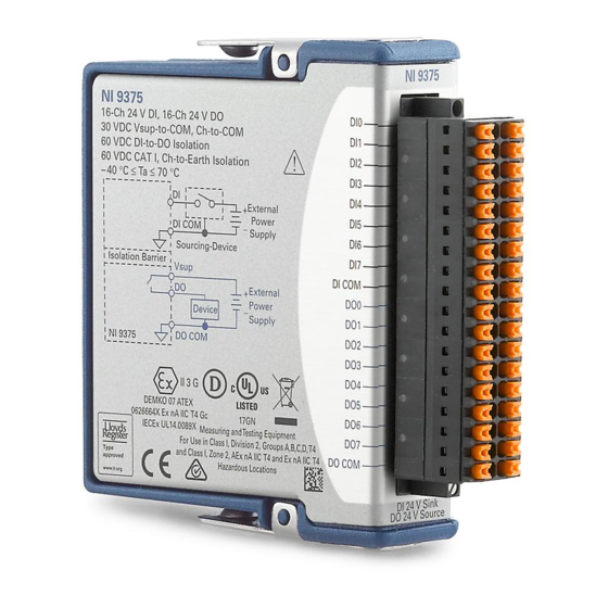
National Instruments NI 9375 Getting Started Manual
16 di/16 do, 30 vdc, 7 ?s sinking di, 500 ?s
sourcing do
Hide thumbs
Also See for NI 9375:
- Getting started manual (23 pages) ,
- Getting started (11 pages) ,
- Getting started (11 pages)
Summary of Contents for National Instruments NI 9375
- Page 1 GETTING STARTED GUIDE NI 9375 16 DI/16 DO, 30 VDC, 7 μs Sinking DI, 500 μs Sourcing DO...
-
Page 2: Safety Guidelines
This document explains how to connect to the NI 9375. In this document, the NI 9375 with spring terminal and the NI 9375 with DSUB are referred to inclusively as the NI 9375. Before you begin, complete the software and... -
Page 3: Safety Voltages
4,000 m dielectric withstand test Measurement Category II is for measurements performed on circuits directly connected to the electrical distribution system. This category refers to local-level electrical distribution, such as NI 9375 Getting Started Guide | © National Instruments | 3... -
Page 4: Ni 9375 With Dsub Isolation Voltages
2,000 m dielectric withstand test Measurement Category I is for measurements performed on circuits not directly connected to the electrical distribution system referred to as MAINS voltage. MAINS is a hazardous live 4 | ni.com | NI 9375 Getting Started Guide... -
Page 5: Safety Guidelines For Hazardous Locations
CAT III, or CAT IV. Safety Guidelines for Hazardous Locations The NI 9375 is suitable for use in Class I, Division 2, Groups A, B, C, D, T4 hazardous locations; Class I, Zone 2, AEx nA IIC T4 and Ex nA IIC T4 hazardous locations; and nonhazardous locations only. -
Page 6: Special Conditions For Hazardous Locations Use In Europe And Internationally
Special Conditions for Hazardous Locations Use in Europe and Internationally The NI 9375 has been evaluated as Ex nA IIC T4 Gc equipment under DEMKO 07 ATEX 0626664X and is IECEx UL 14.0089X 6 | ni.com | NI 9375 Getting Started Guide... - Page 7 II 3G and is suitable for use in Zone 2 hazardous locations, in ambient temperatures of -40 °C ≤ Ta ≤ 70 °C. If you are using the NI 9375 in Gas Group IIC hazardous locations, you must use the device in an NI chassis that has been evaluated as Ex nC IIC T4, Ex IIC T4, Ex nA IIC T4, or Ex nL IIC T4 equipment.
-
Page 8: Electromagnetic Compatibility Guidelines
Furthermore, any changes or modifications to the product not expressly approved by National Instruments could void your authority to operate it under your local regulatory rules. 8 | ni.com | NI 9375 Getting Started Guide... -
Page 9: Special Conditions For Marine Applications
In addition, take precautions when designing, selecting, and installing measurement probes and cables to ensure that the desired EMC performance is attained. NI 9375 Getting Started Guide | © National Instruments | 9... -
Page 10: Preparing The Environment
Preparing the Environment Ensure that the environment in which you are using the NI 9375 meets the following specifications. Operating temperature -40 °C to 70 °C (IEC 60068-2-1, IEC 60068-2-2) Operating humidity 10% RH to 90% RH, (IEC 60068-2-78) noncondensing... - Page 11 DI12 DI13 DI14 DI14 DI15 DI15 DI COM DI COM DO COM DO10 DO10 DO11 DO11 DO12 DO12 DO13 DO13 DO14 DO14 DO15 DO15 V sup Vsup DO COM NI 9375 Getting Started Guide | © National Instruments | 11...
- Page 12 Digital input signal connection DI COM Common reference connection for the digital inputs Digital output signal connection DO COM Common reference connection for the digital outputs No connection Vsup Voltage supply connection 12 | ni.com | NI 9375 Getting Started Guide...
-
Page 13: Sourcing-Output Connections
Connecting Digital Devices You can connect a variety of industrial devices, such as solenoids, motors, actuators, relays, and lamps to the NI 9375. You must connect an external power supply to the NI 9375. The power supply provides the current for the output channels. - Page 14 Vsup and COM pins is powered on. Ensure that the devices you connect to the NI 9375 are compatible with the output specifications of the NI 9375. Refer to the device datasheet at ni.com/manuals...
-
Page 15: Protecting The Digital Outputs From Flyback Voltages
Figure 2. Connecting a Flyback Diode External Power – Supply Flyback Inductive Diode Device DO COM NI 9375 NI 9375 Getting Started Guide | © National Instruments | 15... -
Page 16: Ni 9375 Connection Guidelines
NI 9375 with spring terminal. • For the NI 9375 with spring terminal, push the wire into the terminal when using a solid wire or a stranded wire with a ferrule. - Page 17 I/O Protection Each DO channel on the NI 9375 has circuitry that protects it from overcurrents resulting from a short-circuit or faulty loads. Overvoltage and reverse bias voltage Caution conditions can damage the NI 9375. Check the voltage specifications for all devices that you connect to the NI 9375.
-
Page 18: Where To Go Next
NI 9375 Datasheet NI 9375 Datasheet NI-RIO Help NI-DAQmx Help LabVIEW FPGA Help LabVIEW Help RELATED INFORMATION C Series Documentation Services & Resources ni.com/services ni.com/info cseriesdoc Located at ni.com/manuals Installs with the software 18 | ni.com | NI 9375 Getting Started Guide... -
Page 19: Worldwide Support And Services
You can obtain the DoC for your product by visiting ni.com/certification. If your product supports calibration, you can obtain the calibration certificate for your product at ni.com/calibration. NI 9375 Getting Started Guide | © National Instruments | 19... - Page 20 U.S. Government Customers: The data contained in this manual was developed at private expense and is subject to the applicable limited rights and restricted data rights as set forth in FAR 52.227-14, DFAR 252.227-7014, and DFAR 252.227-7015. © 2017 National Instruments. All rights reserved. 378026A-01 Jan17...


