Emerson Rosemount 3051SF Series Quick Start Manual
Pressure transmitter, flowmeter with advanced hart diagnostics
Hide thumbs
Also See for Rosemount 3051SF Series:
- Quick start manual (52 pages) ,
- Quick installation manual (36 pages) ,
- Quick start manual (48 pages)
Table of Contents
Advertisement
Quick Links
Download this manual
See also:
Quick Start Manual
Quick Start Guide
00825-0300-4801, Rev BB
June 2016
™
Rosemount
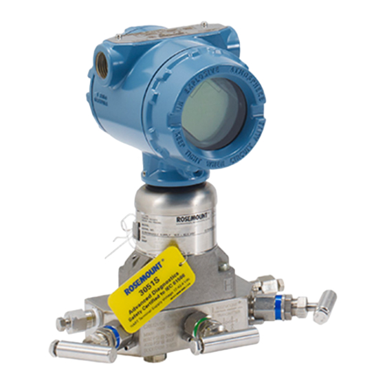
3051S Series Pressure Transmitter
and Rosemount 3051SF Series Flowmeter
®
with Advanced HART
Diagnostics
Note
Before installing the transmitter, confirm the correct device driver is loaded on the host systems.
See
page 3
for system readiness.
Advertisement
Table of Contents

Related Manuals for Emerson Rosemount 3051SF Series


Summary of Contents for Emerson Rosemount 3051SF Series
- Page 1 Quick Start Guide 00825-0300-4801, Rev BB June 2016 ™ Rosemount 3051S Series Pressure Transmitter and Rosemount 3051SF Series Flowmeter ® with Advanced HART Diagnostics Note Before installing the transmitter, confirm the correct device driver is loaded on the host systems.
-
Page 2: Table Of Contents
June 2016 Quick Start Guide NOTICE This guide provides basic guidelines for Rosemount 3051S Series Pressure Transmitters. It does not provide instructions for configuration, diagnostics, maintenance, service, troubleshooting, Explosion-proof, Flameproof, or intrinsically safe (I.S.) installations. Refer to the Rosemount 3051S Reference Manual, Rosemount 3051SFA... -
Page 3: System Readiness
Quick Start Guide June 2016 1.0 System readiness 1.1 Confirm HART Revision capability If using HART based control or asset management systems, confirm the HART capability of those systems prior to transmitter installation. Not all systems are capable of communicating with HART Revision 7 protocol. This transmitter can be configured for either HART Revision 5 or 7. -
Page 4: Transmitter Installation
June 2016 Quick Start Guide 2.0 Transmitter installation 2.1 Mount the transmitter Liquid applications 1. Place taps to the side of the line. 2. Mount beside or below the taps. 3. Mount the transmitter so the drain/vent Flow valves are oriented above process impulse piping. - Page 5 If the transmitter requires the use of a mounting bracket, use the images below ™ for instructions on how to properly mount the transmitter using the Emerson provided mounting brackets. Use only bolts provided with the transmitter or sold as Emerson spare parts.
- Page 6 If the transmitter installation requires assembly of the process flanges, manifolds, or flange adapters, follow these assembly guidelines to ensure a tight seal for optimal performance characteristics of the transmitters. Use only bolts supplied with the transmitter or sold by Emerson as spare parts. Figure 2 illustrates common transmitter assemblies with the bolt length required for proper transmitter assembly.
- Page 7 Quick Start Guide June 2016 Table 2. Torque Values for the Flange and Flange Adapter Bolts Bolt material Head markings Initial torque Final torque Carbon Steel (CS) 300 in-lb 650 in-lb Stainless Steel (SST) 150 in-lb 300 in-lb O-rings with flange adapters Failure to install proper flange adapter O-rings may cause process leaks, which can result in death or serious injury.
-
Page 8: Consider Housing Rotation
June 2016 Quick Start Guide 2.2 Consider housing rotation To improve field access to wiring or to better view the optional LCD display: 1. Loosen the housing rotation set screw using a -in. hex wrench. 2. Rotate the housing clockwise to the desired location. If the desired location cannot be achieved due to thread limit, rotate the housing counter clockwise to the desired location (up to 360°... -
Page 9: Connect The Wiring And Power Up
Quick Start Guide June 2016 Figure 5. Transmitter Switch and Jumper Configuration PlantWeb A. Meter/adjustment module B. Security C. Alarm 2.4 Connect the wiring and power up Use the following steps to wire the transmitter: 1. Remove and discard orange conduit plugs. 2. - Page 10 June 2016 Quick Start Guide Figure 6. PlantWeb Housing Wiring A. RL ≥ 250 Ω B. Power supply Note Installation of the transient protection terminal block does not provide transient protection unless the Rosemount 3051S case is properly grounded. Signal wiring grounding Do not run signal wiring in conduit or open trays with power wiring, or near heavy electrical equipment.
-
Page 11: Verify Configuration
Quick Start Guide June 2016 3. Reinstall the housing cover so metal contacts metal to meet explosion-proof requirements. 4. Plug and seal unused conduit connections with the provided conduit plug. Conduit electrical connector wiring (option GE or GM) For Rosemount 3051S with conduit electrical connectors GE or GM, refer to the cordset manufacturer’s installation instructions for wiring details. -
Page 12: Trim The Transmitter
June 2016 Quick Start Guide Table 3. Fast Key Sequence Function HART 7 Fast Keys HART 5 Fast Keys Damping 2, 2, 1, 1, 3 2, 1, 1, 1, 3 Date 2, 1, 1, 1, 1, 5 2, 1, 1, 1, 1, 4 Descriptor 2, 1, 1, 1, 1, 3 2, 1, 1, 1, 1, 2... -
Page 13: Safety Instrumented Systems
Quick Start Guide June 2016 Using the Field Communicator Fast Keys Steps 1. Equalize or vent the transmitter and connect Field Communicator. 3, 4, 1, 1, 1, 3 2. At the menu, input the Fast Key sequence. 3. Follow the commands to perform a zero trim. Using the transmitter zero adjustment button Push and hold the zero adjustment button for at least two seconds but no longer than ten seconds. -
Page 14: Product Certifications
June 2016 Quick Start Guide 4.0 Product Certifications Rev 1.5 4.1 European Directive Information A copy of the EC Declaration of Conformity can be found at the end of the Quick Start Guide. The most recent revision of the EC Declaration of Conformity can be found at EmersonProcess.com/Rosemount. - Page 15 Quick Start Guide June 2016 IE FM FISCO Certificate: 3012350 Standards: FM Class 3600 – 2011, FM Class 3610 – 2010, FM Class 3611 – 2004, FM Class 3810 – 2005, NEMA 250 – 2003 Markings: IS CL I, DIV 1, GP A, B, C, D; T4(-50 °C ≤ T ≤...
- Page 16 June 2016 Quick Start Guide Temperature class Process temperature -60 °C to +70 °C -60 °C to +80 °C -60 °C to +120 °C Special Conditions for Safe Use (X): 1. The device contains a thin wall diaphragm. Installation, maintenance and use shall take into account the environmental conditions to which the diaphragm will be subjected.
- Page 17 Quick Start Guide June 2016 Special Conditions for Safe Use (X): 1. The Model 3051S Transmitters fitted with transient protection are not capable of withstanding the 500 V test as defined in Clause 6.3.13 of EN 60079-11:2012. This must be taken into account during installation. 2.
- Page 18 June 2016 Quick Start Guide Special Conditions for Safe Use (X): 1. The device contains a thin wall diaphragm. Installation, maintenance and use shall take into account the environmental conditions to which the diaphragm will be subjected. The manufacturer’s instructions for installation and maintenance shall be followed in detail to assure safety during its expected lifetime.
- Page 19 Quick Start Guide June 2016 Model SuperModule 30 V 300 mA 1.0 W 30 nF 3051S...A; 3051SF…A; 3051SAL…C 30 V 300 mA 1.0 W 12 nF 3051S…F; 3051SF…F 30 V 300 mA 1.3 W 3051S …A…M7, M8, or M9; 60 μH 3051SF …A…M7, M8, or M9;...
- Page 20 June 2016 Quick Start Guide Parameters FISCO Capacitance C Inductance L Special Conditions for Safe Use (X): 1. If the apparatus is fitted with optional 90 V transient suppressor, it is not capable of withstanding the 500 V insulation test required by Clause 6.3.13 of IEC60079-11. This must be taken into account when installing the apparatus.
- Page 21 Quick Start Guide June 2016 Model 3051S…F…IB; 3051SF…F…IB 17.5 V 380 mA 5.32 W 3051S …A…M7, M8, or M9; 60 μH 3051SF …A…M7, M8, or M9; 30 V 300 mA 1.0 W 11.4 nF 3051SAL…C… M7, M8, or M9 33 μH 3051SAL or 3051SAM 30 V 300 mA...
- Page 22 June 2016 Quick Start Guide GB50257-1996 “Code for construction and acceptance of electric device for explosion atmospheres and fire hazard electrical equipment installation engineering” GB15577-1995 “Safe regulation for explosive dust atmospheres” GB12476.2-2006 “Electrical apparatus for use in the presence of combustible dust – Part 1-2: Electrical apparatus protected by enclosures and surface temperature limitation –...
- Page 23 Quick Start Guide June 2016 GB3836.15-2000 “Electrical apparatus for explosive gas atmospheres Part 15: Electrical installations in hazardous area (other than mines)” GB3836.16-2006 “Electrical apparatus for explosive gas atmospheres Part 16: Inspection and maintenance of electrical installation (other than mines)” GB50257-1996 “Code for construction and acceptance of electric device for explosion atmospheres and fire hazard electrical equipment installation engineering”...
- Page 24 June 2016 Quick Start Guide IP Republic of Korea Intrinsic Safety Certificate: 12-KB4BO-0202X [HART – Mfg USA], 12-KB4BO-0204X [Fieldbus – Mfg USA], 12-KB4BO-0203X [HART – Mfg Singapore], 13-KB4BO-0296X [Fieldbus – Mfg Singapore] Markings: Ex ia IIC T4 4.13 Combinations K1 Combination of E1, I1, N1, and ND K2 Combination of E2 and I2 K5 Combination of E5 and I5 K6 Combination of E6 and I6...
-
Page 25: Ec Declaration Of Conformity
Quick Start Guide June 2016 Figure 10. Rosemount 3051S Declaration of Conformity EC Declaration of Conformity No: RMD 1044 Rev. X Rosemount Inc. 8200 Market Boulevard Chanhassen, MN 55317-9685 declare under our sole responsibility that the product, Model 3051S Series Pressure Transmitters Model 3051SF Series Flowmeter Transmitters Model 300S Housings manufactured by,... - Page 26 June 2016 Quick Start Guide EC Declaration of Conformity No: RMD 1044 Rev. X EMC Directive (2004/108/EC) This directive is valid until 19 April 2016 EMC Directive (2014/30/EU) This directive is valid from 20 April 2016 All Models Harmonized Standards: EN 61326-1:2013, EN 61326-2-3:2013 PED Directive (97/23/EC) This directive is valid until 18 July 2016 PED Directive (2014/68/EU) This directive is valid from 19 July 2016...
- Page 27 Quick Start Guide June 2016 EC Declaration of Conformity No: RMD 1044 Rev. X Page 3 of 6 Document Rev: 2013_A...
- Page 28 June 2016 Quick Start Guide EC Declaration of Conformity No: RMD 1044 Rev. X ATEX Directive (94/9/EC) This directive is valid until 19 April 2016 ATEX Directive (2014/34/EU) This directive is valid from 20 April 2016 Model 3051S Pressure Transmitters and 3051SF Flowmeter Transmitters BAS01ATEX1303X –...
- Page 29 Quick Start Guide June 2016 EC Declaration of Conformity No: RMD 1044 Rev. X For 3051S transmitters, 300S housings, 3051SFx flowmeters without RTD option: KEMA00ATEX2143X – Flameproof Certificate Equipment Group II, Category 1/2 G Ex d IIC T6…T4 Ga/Gb Harmonized Standards: EN 60079-0:2012, EN 60079-1:2007, EN 60079-26:2007 For 3051SFx flowmeters with RTD options: KEMA00ATEX2143X –...
- Page 30 June 2016 Quick Start Guide EC Declaration of Conformity No: RMD 1044 Rev. X PED Notified Body 3051S Series Pressure Transmitters Det Norske Veritas (DNV) [Notified Body Number: 0575] Veritasveien 1, N-1322 Hovik, Norway ATEX Notified Bodies for EC Type Examination Certificate DEKRA Certification B.V.
- Page 31 Quick Start Guide June 2016 Rosemount 3051S China RoHS List of Rosemount 3051S Parts with China RoHS Concentration above MCVs / Hazardous Substances Hexavalent Polybrominated Polybrominated Part Name Lead Mercury Cadmium Chromium biphenyls diphenyl ethers (Pb) (Hg) (Cd) (Cr +6) (PBB) (PBDE) Electronics...
- Page 32 +65 6777 8211 Standard Terms and Conditions of Sale can be found at www.Emerson.com/en-us/pages/Terms-of-Use.aspx +65 6777 0947 The Emerson logo is a trademark and service mark of Emerson Enquiries@AP.EmersonProcess.com Electric Co. PlantWeb, SuperModule, Rosemount, and Rosemount logotype Middle East and Africa Regional Office are trademarks of Emerson Process Management.