Table of Contents
Advertisement
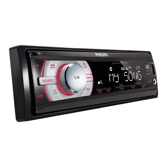
Car audio system
TABLE OF CONTENTS
Technical specification .............................................1-2
Version variation ......................................................1-2
Service measurement setup.....................................1-3
Service aids ............................................................1-4
Instructions on CD playability ..................................2-1..2-2
Disassembly diagram...............................................2
Set Block diagram....................................................3
Set Wiring diagram..................................................4
Circuit diagram
Main board.........................................................5,6
Panel board........................................................7
Tuner board........................................................8
Layout diagram
Main board..........................................................9,10
Panel board........................................................11,12
Tuner board........................................................13,14
Mechanical Exploded view ......................................15
Copyright 2011 Philips Consumer Electronics B.V. Eindhoven, The Netherlands
©
All rights reserved. No part of this publication may be reproduced, stored in a retrieval system or
transmitted, in any form or by any means, electronic, mechanical, photocopying, or otherwise without
the prior permission of Philips.
Published by LX 1145 Service Audio
Version 1.1
Printed in The Netherlands
Subject to modification
CE130/
55,
Page
CE130X
/78
3141 785 35401
Advertisement
Table of Contents

Related Manuals for Philips CE130/55


Summary of Contents for Philips CE130/55
- Page 1 Page Technical specification ..........1-2 Version variation ............1-2 Service measurement setup........1-3 Service aids ............1-4 Instructions on CD playability ........2-1..2-2 Disassembly diagram..........2 Set Block diagram............3 Set Wiring diagram..........4 Circuit diagram Main board............5,6 Panel board............7 Tuner board............8 Layout diagram Main board............9,10 Panel board............11,12 Tuner board............13,14 Mechanical Exploded view ........15 Copyright 2011 Philips Consumer Electronics B.V. Eindhoven, The Netherlands © All rights reserved. No part of this publication may be reproduced, stored in a retrieval system or transmitted, in any form or by any means, electronic, mechanical, photocopying, or otherwise without the prior permission of Philips. 3141 785 35401 Published by LX 1145 Service Audio Printed in The Netherlands Subject to modification Version 1.1...
-
Page 2: Technical Specification
1 - 2 TECHNICAL SPECIFICATION Display • Output power (MAX): 45Wx4 channels • Type: High contrast B/W LCD (8 characters) • Output power (RMS): 22Wx4 channels (4 ohms, • Key illumination: Red 10% T.H.D.) Audio Playback Connectivity • Playback Media: USB flash drive, SD Card •... - Page 3 MEASUREMENT SETUP Tuner FM Bandpass LF Voltmeter 250Hz-15kHz e.g. PM2534 e.g. 7122 707 48001 RF Generator e.g. PM5326 S/N and distortion meter e.g. Sound Technology ST1700B Use a bandpass filter to eliminate hum (50Hz, 100Hz) and disturbance from the pilottone (19kHz, 38kHz). Tuner AM (MW,LW) Bandpass LF Voltmeter...
- Page 4 SERVICE AIDS WARNING All ICs and many other semi-conductors are susceptible to electrostatic discharges (ESD). Careless handling during repair can reduce life drastically. When repairing, make sure that you are connected with the same potential as the mass of the set via a wrist wrap with resistance. Keep components and tools also at this potential.
- Page 5 2 - 1 INSTRUCTIONS ON CD PLAYABILITY Customer complaint "CD related problem" Set remains closed! check playability playability ok ? For flap loaders (= access to CD drive possible) "fast" lens cleaning cleaning method is recommended check playability playability ok ? Play a CD for at least 10 minutes check playability...
- Page 6 2 - 2 INSTRUCTIONS ON CD PLAYABILITY PLAYABILITY CHECK LIQUID LENS CLEANING Before touching the lens it is advised to clean the surface of the lens by blowing clean air over it. For sets which are compatible with CD-RW discs This to avoid that little particles make scratches on use CD-RW Printed Audio Disc ....7104 099 96611 the lens.
- Page 7 DISMANTLING INSTRUCTIONS Note:put on static belt during operation and keep yourself from electronic screw driver static. 1)Detach the the panel by press push button on it. 2)Remove screw on cover "A" 3)Remove cover on unit Main 4)Remove 6pcs 2X6BTP screw on panel button cover'B' 5)Detach the button cover Handy back 面咀+KB板...
- Page 8 BLOCK DIAGRAM...
- Page 9 WIRING DIAGRAM...
-
Page 10: Main Board
CIRCUIT DIAGRAM MAIN BOARD... -
Page 11: Main Board
CIRCUIT DIAGRAM MAIN BOARD... - Page 12 CIRCUIT DIAGRAM PANEL BOARD RED+8V CEM2000-LCD R963 NC BLUE+8V LCD1 RED+8V R964 Q901 BLUE+8V R935 LED7 LED9 LED11 LED3 LED6 Q903 LED13 LED15 R938 R939 R958 RED+8V BLUE+8V R937 C901 Q904 680P R965 Q902 R936 LED8 LED10 LED14 LED2 LED17 LED16 LED4 LED5...
-
Page 13: Tuner Board
CIRCUIT DIAGRAM TUNER BOARD TUNER PART R101 270K Q104 C101 3SK254 C121 R100 R108 L102 100R 220NH C123 C120 C122 C118 C115 TUNER-3V3 TUN-LCH 33NF C116 L106 33UH C102 RFGND TUN-RCH LOUT CHGND SI4740/41 C109 CTUNE ROUT CHGND C103 C110 Q102 R102 MF862... - Page 14 MAIN PCB COMPONENT LAYOUT TOP SIDE VIEW...
- Page 15 MAIN PCB COMPONENT LAYOUT BOTTOM SIDE VIEW...
- Page 16 PANEL PCB COMPONENT LAYOUT TOP SIDE VIEW...
- Page 17 PANEL PCB COMPONENT LAYOUT BOTTOM VIEW PANEL PCB COMPONENT LAYOUT BOTTOM VIEW...
- Page 18 TUNER PCB COMPONENT LAYOUT TOP SIDE VIEW...
- Page 19 TUNER PCB COMPONENT LAYOUT BOTTOM IDE VIEW...
- Page 20 SET EXPLODER VIEW DRAWING...
-
Page 21: Reset
TROUBLE SHOOTING CAUSE ANALYSIS NO. DEFECTIVE a. Whether the 7.5A fuse of ISO connector is normal b. Whether the power supply 5V of CPU--IC202 LM2950 is normal c. Whether there is any cold solder/bridge solder of CPU--IC201 MC81F4216D d. Whether there is any oscillation or detuning of crystal--CF201 32.768 e. - Page 22 BX8804/8805 User’s Manual Revision 0.93 May 23, 2008 ...
- Page 23 BX8804/8805 Revision History Revision Date Revision Description 0.91 May 21, 2008 First Release 0.92 May 22, 2008 ‐ Correct external interrupt 8, 9, 10, 11 of pin description (refer 1.5.1) ‐ Add PLL1_CON(0x88000C), PLL1_LOCK (refer 6.5) ‐ Add PLL3_CON(0x880014), PLL3_SEL, PLL3_LOCK (refer 6.5) ‐ Change reset value of DAC_CLK_CON(0x870048) (refer 7.3) ‐ Register HU0CON(0x88A000), RFTL, TFTL, bit/description modify (refer 12.2) ‐ Register GPMODE0(0x884010), GP02MODE, description modify (refer 15.2) ‐ Add electrical characteristics of USB (refer 21.2) 0.93 May 23, 2008 ‐ Correct PLL power pins of pin configuration (refer [Figure 1]) 2/21...
- Page 24 BX8804/8805 ABLE OF ONTENTS ............................... 9 RODUCT VERVIEW .............................. 10 NTRODUCTION ................................. 10 EATURES .............................. 12 PPLICATIONS ............................ 13 IN ONFIGURATION 1.4.1 ............................... 13 PIN ............................... 14 IN ESCRIPTION 1.5.1 ............................... 14 ................................ 18 IN ESCRIPTION ................................ 19 OWER ................................ 19 LOCK ................................ 19 ESET CD‐DSP...
- Page 25 BX8804/8805 4.7.6 ................................. 39 BORT 4.7.7 ......................... 40 OFTWARE INTERRUPT INSTRUCTION 4.7.8 .......................... 40 NDEFINED INSTRUCTION 4.7.9 ............................ 41 XCEPTION ECTORS 4.7.10 E ............................ 41 XCEPTION RIORITIES ................................ 41 ESET ............................ 43 NIFIED ACHE RCHITECTURE ................................ 44 VERVIEW ............................ 44 ACHE PERATION .............................. 46 YSTEM ONFIGURATIONS ................................ 47 VERVIEW ...
- Page 26 BX8804/8805 13.1 ............................... 145 EATURES 13.2 .............................. 145 EGISTERS 14. T .............................. 147 IMER ONTROLLER 14.1 .............................. 148 VERVIEW 14.2 ............................ 148 IMER EGISTERS 15. GPIO .................................. 154 15.1 .............................. 155 VERVIEW 15.2 GPIO ............................. 155 EGISTERS 16. I .............................. 195 NTERRUPT ONTROLLER 16.1 .............................. 196 VERVIEW 16.2...
- Page 27 BX8804/8805 List of Figures BX8805 (128‐TQFP‐1414 ) ............... 13 IGURE ACKAGE IAGRAM OF ARM7TDMI ........................ 30 IGURE EMORY ORMAT ...................... 33 IGURE EGISTER ORGANIZATION IN STATE ...................... 34 IGURE EGISTER ORGANIZATION IN HUMB STATE ‐ ARM‐ .............. 35 IGURE APPING OF HUMB STATE REGISTERS ONTO STATE REGISTERS ...................... 36 IGURE ...
- Page 28 BX8804/8805 IST OF ABLES BX8805 (144‐TQFP‐2020) .................... 14 ABLE IN ESCRIPTION OF ............................... 19 ABLE OWER .............................. 19 ABLE LOCK .............................. 19 ABLE ESET CD‐DSP .......................... 20 ABLE NTERFACE ............................. 20 ABLE NTERFACE ARM7TDMI™ ..................... 21 ABLE YSTEM ...
- Page 29 BX8804/8805 ‐P ........................ 243 ABLE ROCESSOR OMMAND .......................... 249 ABLE HARACTERISTICS .......................... 249 ABLE HARACTERISTICS 8/21...
- Page 30 BX8804/8805 1. P RODUCT VERVIEW 9/21...
-
Page 31: F Eatures
BX8804/8805 1.1 I NTRODUCTION T he BX8805 is designed as a System On a Chip: system controller and decoder controller for multi‐format digital audio player with access of various storage such as USB, SD/MMC card, NOR flash and etc. The independent dual 32‐bit RISC processors provide optimum performance and code density for the combination of control code and signal processing required for digital audio decoding, file system management and system control. The BX8805 integrates programmable and approved ARM7TDMI™ as a system controller, MCS Logic proprietary 32‐bit RISC‐DSP processor for advanced multi‐format digital audio (MP3/WMA/Ogg) decoding, low power dedicated hard‐ wired CDROM decoder, On‐chip SRAM and ROM, versatile audio interfaces of USB 1.1 host/device, SD/MMC card, and large number of GPIO (General Purpose Input Output) ports. In addition, SRS (WOW), MP3 encoding and WMA encoding features are available as system solutions. By utilizing advanced 0.13 micron technology, the BX8805 is the perfect solution for digital audio products with low power requirements; high performance and powerful processing in 144 TQFP and 128 TQFP packages. 1.2 F EATURES Process Low power 0.13 um CMOS technology Core Supply power : 1.2 V ± 10% IO supply power : 3.3 V ± 10% Operating up to 96 MHz Architecture Independent Dual Processor architecture 32 bit ARM7TDMI™ RISC processor for system control 32 bit MCS Logic proprietary RISC‐DSP processor for audio processing Package Type 128 TQFP Memory 4‐Kbyte Unified Cache SRAM 2‐Kbyte On‐chip Data SRAM 4‐Kbyte On‐chip general purpose Data SRAM Maximum 256‐Mbit SDRAM interface with 16‐bit data width Maximum 32‐Mbit parallel NVRAM interface with 16‐bit data width GPIO ... - Page 32 BX8804/8805 One 2‐wire Asynchronous serial interface with IrDA functionality One 4‐wire high speed Asynchronous serial interface CUART One 2‐wire Asynchronous serial interface with IrDA functionality I2C Master / Slave mode operation only Baud rate generation for serial clock I2S 4 wire audio data interface Basic Timer & Watchdog Timer Three timers with PWM functionality One Watchdog timer General Purpose DMA One general purpose DMA control block A/D Converter One 9‐bit resolution 8‐channel high speed ADC USB 1.1 Full‐speed Host controller USB Rev 1.1 compatible, Open HCI Rev 1.0 compatible Support for both low speed and full speed USB devices USB 1.1 Full‐speed Device controller 4 end point, 1152 byte FIFO Compliant to USB 1.1 specification Support FS(Full Speed, 12Mbps) Support Control, Bulk, ISO and Interrupt transfer Co‐processor and Functions MPEG 1/2/2.5 layer2 and 3 decoding Window Media Audio (WMA V9 compatible) decoding Audio decoding of Window Media Video (WMV) Advanced System Format (ASF) decoding Ogg Vorbis (by Q10) decoding High quality MLPCM voice recording MPEG 1/2/2.5 layer 3 Real time Encoding Window Media Audio (WMA V8) Real time Encoding Supports SRS (WOW) sound effect Supports software mute/pause/resume/volume Digital volume control 7‐band sound / graphic equalizer for MP3, WMA, Ogg and Red book audio CD Optional sampling rate conversion to 44.1Khz for off‐chip general audio DAC ...
- Page 33 BX8804/8805 High quality ESP sound with high compression rate Format Decoding ID3 tag V1.1, V2.2 , V2.3 extraction FAT12, FAT16, FAT32 file type ISO9660 CDROM Mode1/Mode2 format Joliet decoding both single session and multi session disc Joliet Level 3 UDF V1.02/V1.5/V2.01 UDF in packet writing format Sorting directories and files in name order playing list file 1.3 A PPLICATIONS Portable MP3/WMA/Ogg Player ( Flash or CD type ) MP3 Juke box Car Audio Digital audio Encoder/Decoder Digital Internet Radio server Multimedia Storage Device 12/21...
- Page 34 BX8804/8805 1.4 P IN ONFIGURATION 1.4.1 128 PIN GP05 GP04 GP03 GP29 ECSN GP30 EOEN GP31 EWEN GP32 EAD20 GP33 EAD19 GP34 EAD18 GP35 EAD17 GP36 RESETN CASN NTRST SDCLK VSS33 VSS33 TEST VDD33 BX8805 RASN VDD33 VSS12 VSS33 VDD12 USBVDD33...
- Page 35 BX8804/8805 1.5 P IN ESCRIPTION 1.5.1 128 [Table 1] BX8805 (144‐TQFP‐2020) IN ESCRIPTION OF Pin Name Type Description Alternative Function 1 ADIN1 I ADC analog input[1] 2 ADIN0 I ADC analog input[0] 3 AVDD33 P ADC Analog Power supply (3.3V) 4 AVSS33 P ADC Analog Ground 5 GP00 ...
- Page 36 BX8804/8805 39 AD11 O External SDRAM address bus [11] External program address bus [11] 40 AD12 O External SDRAM address bus [12] External program address bus [12] 41 BA0 O External SDRAM Bank selector 0 External program address bus [13] 42 BA1 O External SDRAM Bank selector 1 External program address bus [14] 43 LDQM O SDRAM Lower byte data mask External program address bus [15] 44 UDQM O SDRAM Upper byte data mask External program address bus [16] 45 SDCSN O SDRAM Chip select 46 VDD12 P Digital power supply (1.2V) 47 VSS12 ...
- Page 37 BX8804/8805 I2C SDA 76 GP17 B General Purpose IO 17 SPI1 CS 77 GP18 B General Purpose IO 18 SPI1 CK 78 GP19 B General Purpose IO 19 SPI1 MISO 79 GP20 B General Purpose IO 20 SPI1 MOSI External Interrupt 3 80 GP21 B General Purpose IO 21 SPI2 CS 81 DDATA O Audio serial data for external DAC 82 IOVDD33 P I/O Power supply (3.3V) 83 IOVSS33 P I/O Ground 84 ...
- Page 38 BX8804/8805 this pin. 99 TCK I JTAG Clock Input 100 GP29 B General Purpose IO 29 CDDSP SCOR0 101 GP30 B General Purpose IO 30 CDDSP BCLK0 102 GP31 B General Purpose IO 31 CDDSP DATA0 103 GP32 B General Purpose IO 32 CDDSP LRCK0 104 GP33 B General Purpose IO 33 SBDT0 105 GP34 B General Purpose IO 34 SBCK Timer0 Output 106 GP35 B General Purpose IO 35 ...
- Page 39 BX8804/8805 ACKAGE IMENSIONS 18/21...
- Page 40 BX8804/8805 20.1 BX8805 ACKAGE IMENSION 20.1.1 128 ...
- Page 41 BX8804/8805 LECTRICAL HARACTERISTICS 20/21...
-
Page 42: R Egisters
BX8804/8805 21.1 HARACTERISTICS [Table 47] HARACTERISTICS Name Description Max Unit PVDD/PVSS 3.3V IO Pre‐Driver Supply Voltage 3.6 DVDD/DVSS 3.3V IO Post‐Driver Supply Voltage 3.6 VDD/VSS 1.2V IO Pre‐Driver Supply Voltage 1.08 1.32 Temp Temperature ‐40 125 VIL Input Low Voltage ‐0.3 0.8 VIH Input High Voltage 5.5 VT+ Schmitt Trigger L‐to‐H Threshold 1.74 VT‐ Schmitt Trigger L‐to‐L Threshold 1.07 ... - Page 43 FEDD56V16160F-02 1 Semiconductor This version: March. 2001 Previous version : January. 2001 MSM56V16160F 2-Bank × × × × 524,288-Word × × × × 16-Bit SYNCHRONOUS DYNAMIC RAM DESCRIPTION The MSM56V16160F is a 2-Bank × 524,288-word × 16-bit Synchronous dynamic RAM fabricated in Oki’s silicon-gate CMOS technology.
- Page 44 FEDD56V16160F-02 1 Semiconductor MSM56V16160F PIN CONFIGURATION (TOP VIEW) DQ16 DQ15 DQ14 DQ13 DQ12 DQ11 DQ10 LDQM UDQM 50-Pin Plastic TSOP (II) (K Type) Pin Name Function Pin Name Function System Clock UDQM, LDQM Data Input / Output Mask Chip Select Data Input / Output Clock Enable Power Supply (3.3V)
- Page 45 FEDD56V16160F-02 1 Semiconductor MSM56V16160F PIN DESCRIPTION Fetches all inputs at the “H” edge. Disables or enables device operation by asserting or deactivating all inputs except CLK, CKE, UDQM and LDQM. Masks system clock to deactivate the subsequent CLK operation. If CKE is deactivated, system clock will be masked so that the subsequent CLK operation is deactivated.
-
Page 46: R Egisters
FEDD56V16160F-02 1 Semiconductor MSM56V16160F BLOCK DIAGRAM Latency Progra- & Burst Controller ming Controller Register Timing Register UDQM Bank LDQM Controlle Internal Col. Address Counter Input Input A0−A11 Data Buffers Registe Column Column Address Decoders Buffers Sense Amplifiers −DQ16 Read Output Buffers Data Internal... - Page 47 FEDD56V16160F-02 1 Semiconductor MSM56V16160F ELECTRICAL CHARACTERISTICS ABSOLUTE MAXIMUM RATINGS Parameter Symbol Value Unit Voltage on Any Pin Relative to V –0.5 to V + 0.5 Supply Voltage –0.5 to 4.6 Storage Temperature –55 to 150 °C Power Dissipation Short Circuit Output Current -20 to 85 °C Operating Temperature...
- Page 48 FEDD56V16160F-02 1 Semiconductor MSM56V16160F DC CHARACTERISTICS MSM56V16160 Condition F-10 Parameter Unit Note Symbol Bank Others Min. Max. Min. Max. Output High =−2.0mA Voltage Output Low =2.0mA Voltage Input Leakage −10 −10 µA...
-
Page 49: R Egisters
FEDD56V16160F-02 1 Semiconductor MSM56V16160F Mode Set Address Keys CAS Latency Burst Type Burst Length BT = 0 BT = 1 Reserved Sequential Interleave Reserved Reserved Reserved Reserved Reserved Reserved Reserved Reserved Reserved Reserved Full Page Reserved Notes: A7, A8, A9, A10 and A11 should stay “L” during mode set cycle. MSM56V16160F support two methods of Power on Sequence. - Page 50 FEDD56V16160F-02 1 Semiconductor MSM56V16160F AC CHARACTERISTICS (1/2) Note 1,2 MSM56V16160 Parameter Symbol Unit Note F-10 Min. Max. Min. Max. CL = 3 Clock Cycle Time CL = 2 CL = 1 CL = 3 ...
- Page 51 FEDD56V16160F-02 1 Semiconductor MSM56V16160F AC CHARACTERISTICS (2/2) Note 1,2 MSM56V16160 Parameter Symbol Unit Note F-10 Min. Max. Min. Max. Data Input Mask Time from Write Cycle Command Data Output High Impedance Time Cycle from Precharge Command Active Command Input Time from Mode Register Set Command Input Cycle (Min.)
- Page 52 FEDD56V16160F-02 1 Semiconductor MSM56V16160F TIMING CHART CAS Latency= = = = 2, Burst Length= = = = 4 Read & Write Cycle (Same Bank) @CAS ADDR Qa2 Qa3 Db0 Db1 Db2 Db3 UDQM, LDQM Row Active Row Active Read Command Precharge Command Write Command Precharge Command...
- Page 53 FEDD56V16160F-02 1 Semiconductor MSM56V16160F CAS Latency= = = = 2, Burst Length=4 Single Bit Read-Write-Read Cycle (Same Page) @CAS High ADDR UDQM, LDQM Row Active Write Command Precharge Command Read Command Read Command 11/31...
- Page 54 FEDD56V16160F-02 1 Semiconductor MSM56V16160F *Note: 1. When CS is set “High” at a clock transition from “Low” to “High”, all inputs except CKE, UDQM and LDQM are invalid. 2. When issuing an active, read or write command, the bank is selected by A11. Active, read or write Bank A Bank B...
- Page 55 FEDD56V16160F-02 1 Semiconductor MSM56V16160F CAS Latency= = = = 2, Burst Length=4 Page Read & Write Cycle (Same Bank) @CAS High Bank A Active ADDR Qa0 Qa1 Qb0 Qb1 Dc0 Dc1 Dd0 ∗Note 2 ∗Note 1 UDQM, LDQM Read Command Write Command Precharge Command Read Command...
- Page 56 FEDD56V16160F-02 1 Semiconductor MSM56V16160F Read & Write Cycle with Auto Precharge @ Burst Length= = = = 4 High ADDR CAS Latency=1 Qa1 Qa2 Qa3 Db0 Db1 Db2 Db3 A-Bank Precharge Start UDQM, LDQM CAS Latency=2 Qa0 Qa1 Qa2 Qa3 Db0 Db1 Db2 Db3 A-Bank Precharge Start UDQM,...
- Page 57 FEDD56V16160F-02 1 Semiconductor MSM56V16160F Bank Interleave Random Row Read Cycle @CAS Latency=2, Burst Length=4 High ADDR QAa0 QAa1 QAa2 QAa3 QBb1 QBb2 QBb3 QBb4 QAc0 QAc1 QAc2 QAc3 UDQM, LDQM Row Active Read Command Read Command Row Active (A-Bank) (B-Bank) (A-Bank) (B-Bank) Read Command...
- Page 58 FEDD56V16160F-02 1 Semiconductor MSM56V16160F Bank Interleave Random Row Write Cycle @CAS Latency=2, Burst Length=4 High ADDR DAa0 DAa1 DAa2 DAa3 DBb0 DBb1 DBb2 DBb3 DAc0 DAc1 UDQM, LDQM Row Active Row Active Precharge Command Write Command (A-Bank) (B-Bank) (A-Bank) (A-Bank) Precharge Command Write Command Precharge Command...
- Page 59 FEDD56V16160F-02 1 Semiconductor MSM56V16160F Bank Interleave Page Read Cycle @CAS Latency=2, Burst Length=4 High ∗Note 1 ADDR QAa0 QAa1 QAa2 QAa3 QBb0 QBb1 QBb2 QBb3 QAc0 QAc1 QBd0 QBd1 QAe0 QAe1 UDQM, LDQM Row Active Row Active Read Command Precharge Command (A-Bank) (B-Bank) (B-Bank)
- Page 60 FEDD56V16160F-02 1 Semiconductor MSM56V16160F CAS Latency=2, Burst Length= = = = 4 Bank Interleave Page Write Cycle @CAS High ADDR DAa0 DAa1 DAa2 DAa3 DBb0 DBb1 DBb2 DBb3 DAc0 DAc1 DBd0 UDQM, LDQM Row Active Row Active Write Command (A-Bank) (B-Bank) (B-Bank) Precharge Command...
- Page 61 FEDD56V16160F-02 1 Semiconductor MSM56V16160F CAS Latency=2, Burst Length=4 Bank Interleave Random Row Read/Write Cycle @CAS High ADDR QAa0 QAa1 QAa2 QAa3 QBb0 QBb1 QBb2 QBb3 QAc0 QAc1 QAc2 QAc3 UDQM, LDQM Row Active Row Active Write Command Read Command (A-Bank) (B-Bank) (B-Bank) (A-Bank)
- Page 62 FEDD56V16160F-02 1 Semiconductor MSM56V16160F CAS Latency=2, Burst Length=4 Bank Interleave Page Read/Write Cycle @CAS High CAa0 CBb0 CAc0 ADDR QAa0 QAa1 QAa2 QAa3 DBb0 DBb1 DBb2 DBb3 QAc0 QAc1 QAc2 QAc3 UDQM, LDQM Read Command Write Command Read Command (A-Bank) (B-Bank) (A-Bank) 20/31...
- Page 63 FEDD56V16160F-02 1 Semiconductor MSM56V16160F CAS Latency=2, Burst Length=4 Clock Suspension & DQM Operation Cycle @CAS ∗Note 1 ∗Note 1 ADDR Qa0 Qa1 Qb0 Qb1 ∗Note 3 ∗Note 2 UDQM, LDQM CLOCK Read Command Write Write DQM Read DQM Row Active Suspension Read Command Write...
- Page 64 FEDD56V16160F-02 1 Semiconductor MSM56V16160F CAS Latency=2, Burst Length=4 Read to Write Cycle (Same Bank) @CAS ∗Note 1 ADDR Db0 Db1 Db2 Db3 UDQM, LDQM Precharge Command Row Active Read Command Write Command *Note: 1. In Case CAS latency is 3, READ can be interrupted by WRITE. The minimum command interval is [burst length + 1] cycles.
- Page 65 FEDD56V16160F-02 1 Semiconductor MSM56V16160F Read Interruption by Precharge Command @Burst Length= = = = 8 High ADDR CAS Latency=1 ∗Note 1 Qa0 Qa1 Qa3 Qa4 Qa5 UDQM, LDQM CAS Latency=2 ∗Note 1 Qa0 Qa1 Qa2 Qa3 Qa4 Qa5 UDQM, LDQM CAS Latency=3 ∗Note 1 Qa0 Qa1 Qa2 Qa3 Qa4...
- Page 66 FEDD56V16160F-02 1 Semiconductor MSM56V16160F Burst Stop Command @Burst Length=8 High ADDR CAS Latency=1 Qa0 Qa1 Qa2 Qa3 Qa4 Qb0 Qb1 Qb2 Qb3 Qb4 UDQM, LDQM CAS Latency=2 Qa0 Qa1 Qa2 Qa3 Qa4 Qb0 Qb1 Qb2 Qb3 Qb4 UDQM, LDQM CAS Latency=3 Qa0 Qa1 Qa2 Qa3 Qa4 Qb0 Qb1 Qb2 Qb3 Qb4 UDQM,...
- Page 67 FEDD56V16160F-02 1 Semiconductor MSM56V16160F Power Down Mode @CAS Latency=2, Burst Length=4 ∗Note 2 ∗Note 1 (min.) ADDR Qa0 Qa1 Qa2 UDQM, LDQM Power-down Read Command Entry Active Power-down Clock Clock Precharge Command Exit Suspension Suspension Exit Entry *Note: 1. When both banks are in precharge state, and if CKE is set low, then the MSM56V16160F enters power-down mode and maintains the mode while CKE is low.
- Page 68 FEDD56V16160F-02 1 Semiconductor MSM56V16160F Self Refresh Cycle ADDR Hi-Z UDQM, LDQM Self Refresh Entry Self Refresh Exit Row Active 26/31...
- Page 69 FEDD56V16160F-02 1 Semiconductor MSM56V16160F Mode Register Set Cycle Auto Refresh Cycle High High ADDR Hi - Z Hi - Z UDQM, LDQM New Command Auto Refresh Auto Refresh 27/31...
- Page 70 FEDD56V16160F-02 1 Semiconductor MSM56V16160F FUNCTION TRUTH TABLE (Table 1) (1/2) Current ADDR Action State Idle ILLEGAL 2 ILLEGAL 2 Row Active NOP 4 Auto-Refresh or Self-Refresh 5 OP Code Mode Register Write Row Active CA, A10 Read CA, A10 Write ILLEGAL 2 Precharge ILLEGAL...
- Page 71 FEDD56V16160F-02 1 Semiconductor MSM56V16160F FUNCTION TRUTH TABLE (Table 2) (2/2) Current ADDR Action State ILLEGAL Write with Auto ILLEGAL 2 RA, A10 Precharge ILLEGAL NOP --> Idle after t RP Precharge NOP --> Idle after t RP ILLEGAL 2 ILLEGAL 2 ILLEGAL 2 NOP 4 ILLEGAL...
- Page 72 FEDD56V16160F-02 1 Semiconductor MSM56V16160F FUNCTION TRUTH TABLE for CKE (Table 2) Current State (n) CKEn-1 CKEn ADDR Action INVALID Self Refresh Exit Self Refresh --> ABI Exit Self Refresh --> ABI ILLEGAL ILLEGAL ILLEGAL NOP (Maintain Self Refresh) INVALID Power Down Exit Power Down -->...
- Page 73 FEDD56V16160F-02 1 Semiconductor MSM56V16160F NOTICE 1. The information contained herein can change without notice owing to product and/or technical improvements. Before using the product, please make sure that the information being referred to is up-to-date. 2. The outline of action and examples for application circuits described herein have been chosen as an explanation for the standard action and performance of the product.