Table of Contents
Advertisement
Jul. 2007
Table of Contents
Cautionary Notes ..............................................................2
Specications........................................................................2
Location of Controls .........................................................4
Location of Controls Parts List........................................5
Exploded View (Cabinet).................................................6
Exploded View (Cabinet) Parts List ...............................7
Exploded View (Chassis) .................................................8
Exploded View (Chassis) Parts List................................9
Parts List ...........................................................................10
Verifying the Version Number......................................14
Test Mode .........................................................................14
Block Diagram/Wiring Diagram..................................20
Copyright © 2007 ROLAND CORPORATION
All rights reserved. No part of this publication may be reproduced in any form without the written permission
of ROLAND CORPORATION.
Circuit Board (Main, XLR Board)..................................22
Circuit Diagram (Main Board: Digital) ........................24
Circuit Diagram (Main Board: Power Supply) ...........28
Circuit Board (Jack Board) .............................................30
Circuit Diagram (Jack Board) ........................................32
Circuit Board (Panel Board)...........................................34
Circuit Diagram (Panel Board)......................................36
Circuit Board ( PS1 Board)..............................................38
Circuit Diagram (PS1 Board) .........................................39
Circuit Board (Amp Board)............................................40
Circuit Diagram (Amp Board).......................................42
17058507E0
SERVICE NOTES
Issued by RJA
Printed in Japan (0400) (SC-MZ)
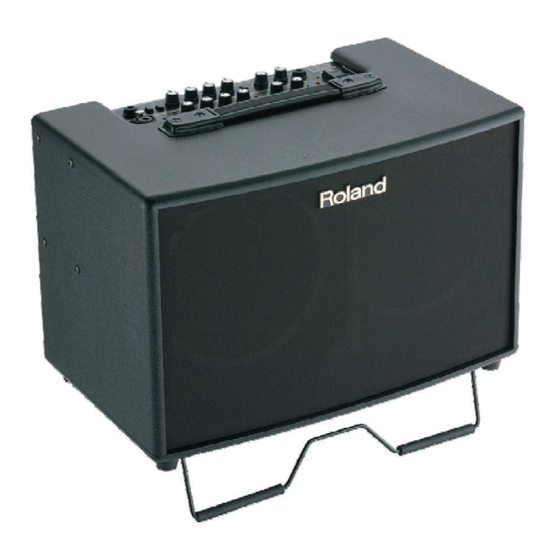
AC-90
Advertisement
Table of Contents

Related Manuals for Roland AC-90


Summary of Contents for Roland AC-90
-
Page 1: Table Of Contents
Test Mode .................14 Circuit Board (Amp Board)..........40 Block Diagram/Wiring Diagram........20 Circuit Diagram (Amp Board)........42 Copyright © 2007 ROLAND CORPORATION All rights reserved. No part of this publication may be reproduced in any form without the written permission of ROLAND CORPORATION. 17058507E0... -
Page 2: Cautionary Notes
Jul. 2007 AC-90 Cautionary Notes Specications AC-90:Acoustic Chorus Before beginning the procedure, please read ● Rated Power Output through this document. The matters described may 45W + 45W ● Nominal Input Level (1 kHz) differ according to the model. GUITAR Channel: -10 dBu... - Page 3 Jul. 2007 AC-90 ● Accessories Carrying Case (#SD000999) Owner’s Manual (multi-languages E/G/F/I/S/P/D) (#SD000994) ● Options Owner’s Manual (Japanese/#SD000992) Foot Switch: BOSS FS-5L (Mute On/Off) BOSS FS-5U BOSS FS-6 Connection Cable: PCS-31 * In the interest of product improvement, the specifications and/ or appearance of...
-
Page 4: Location Of Controls
Jul. 2007 AC-90 Location of Controls fig.panel.eps... -
Page 5: Location Of Controls Parts List
Jul. 2007 AC-90 Location of Controls Parts List Part Code Part Name Description Q’ty 13449146 6.5MM JACK YKB21-5102 (W/SW) 22150756 JACK NUT 2 SD000099 PUSH SWITCH ESB64619 SD000082 PUSH BUTTON SD000091 POTENTIOMETER RK09L1140 10KB 40452178 VR WASHER M9 17048630 VR ACCESSORY NUT M9... -
Page 6: Exploded View (Cabinet)
Jul. 2007 AC-90 Exploded View (Cabinet) fig.bunkai-cabinet.eps Speaker Jack Connection Diagram (Front View) Bottom View Rear View... -
Page 7: Exploded View (Cabinet) Parts List
Jul. 2007 AC-90 Exploded View (Cabinet) Parts List Parts Part Code Part Name Description Q’ty ******** CHASSIS ASSY SD001004 CABINET ASSY NOTE: ‘CABINET ASSYNOTE’ includes the following parts. ******** ACOUSTIC FOAM A ******** ACOUSTIC FOAM B ******** ACOUSTIC FOAM C... -
Page 8: Exploded View (Chassis)
Jul. 2007 AC-90 Exploded View (Chassis) fig.bunkai-chassis.eps Cushion Chassis Attachment (Front Panel) Affix lined up with the chassis border lines. The direction differs depending on the AC cord specifications. PS1 Board Fuse Rating Indication 100VJ/117VU/117VUC Specifications 230VE/230VG/240VA Specifications • Use Bel Fuse "5ST 5A 250V."... -
Page 9: Exploded View (Chassis) Parts List
Jul. 2007 AC-90 Exploded View (Chassis) Parts List Parts Part Code Part Name Description Q’ty SD001009 TRANSFORMER PT-BG435 100V/117V SD001010 TRANSFORMER PT-BG435 230V/240V SD000177 AC CORD PSE SP-18A WITH TERMINAL 100V SD000912 AC CORD ASSY SP-20 117V(2P) SD000913 AC CORD ASSY... -
Page 10: Parts List
Jul. 2007 AC-90 Parts List fig.part1e Due to one or more of the following reasons, SAFETY PRECAUTIONS: parts with parts code ******** cannot be supplied as service parts. The parts marked have safety-related characteristics. Use only listed parts for replacement. - Page 11 Jul. 2007 AC-90 PWB ASSY SD000990 AMP BOARD ASSY NOTE: ‘AMP BOARD ASSY’ includes the following part. ******** PS1 BOARD NOTE: excluding the fuse. SD000989 MAIN BOARD ASSY NOTE: ‘MAIN BOARD ASSY’ includes the following parts. ******** MAIN BOARD ********...
- Page 12 Jul. 2007 AC-90 PACKING SD001000 CUSHION PAD (DH NO.:604-AC-90) SD000518 BOTTOM PAD SD000998 PACKING CASE MISCELLANEOUS SD001013 CUSHION CHASSIS S CHASSIS SD001012 CUSHION CHASSIS L CHASSIS 03782323 SW HOLDER AT-218K SD000153 CABLE CLAMP 412-PGYL-3 STAY SD000853 CUSHION 3X32 HI CHASSIS...
- Page 13 Jul. 2007 AC-90...
-
Page 14: Verifying The Version Number
• The TIP: CHORUS, RING: REVERB/DELAY foot switch is indicated as • Boss FS-5U foot switches (sold separately) -- 2 [Foot SW 2]. • Roland PCS-31 foot-switch connection cable (sold separately)) -- 1 fig.footSW.eps • Tester (for measuring voltage) • Boss DI-1 (only when inspecting the signal level) •... - Page 15 • Depressing the [TIP] (white) foot switch makes execution advance to the MIC/LINE channel [CHORUS] LED next test item. [ANTI-FEEDBACK] LED [MUTE] LED • Inserting a plug into [Foot SW 1] on the AC-90 makes the following LEDs light up. GUITAR channel [CHORUS] LED MIC/LINE channel [CHORUS] LED [ANTI-FEEDBACK] LED [MUTE] LED 10.
- Page 16 • Set the measurement range on the tester to 50 V or higher. • Insert a PCS-31 plug into [Foot SW 1] on the AC-90 and depress the [TIP] • Bring [COM] (black) on the tester into contact with the [1: GND] (white) foot switch to make execution advance to the next inspection test.
- Page 17 [MUTE] LED • After that, the [ANTI-FEEDBACK] and [MUTE] LEDs light up as a display to identify the AC-90. * The LEDs are used to confirm whether inspection tests are passed or failed, so verify that the following LEDs are able to flash.
- Page 18 [MUTE] LED • After that, the [ANTI-FEEDBACK] and [MUTE] LEDs light up as a display to identify the AC-90. * The LEDs are used to confirm whether inspection tests are passed or failed, so verify that the following LEDs are able to flash.
- Page 19 Jul. 2007 AC-90 6. Output-level Confirmation With a dummy load resistor connected to the output jacks according to the following table, check the signal level at each end of the dummy resistor. * The values shown are a rough guide. Actual values are subject to volume-production fluctuations. (Approx. +/-1.5 dBu with respect to the values in the table below) * For the dummy load resistor, use the plug indicated under “Connection plug”...
-
Page 20: Block Diagram/Wiring Diagram
Jul. 2007 AC-90 Block Diagram/Wiring Diagram fig.AC90-block.eps@L... -
Page 21: Circuit Board (Main, Xlr Board)
Jul. 2007 AC-90 Circuit Board (Main, XLR Board) fig.AC90-pcb-main-01.eps@L... -
Page 22: Circuit Diagram (Main Board: Digital)
Jul. 2007 AC-90 Circuit Diagram (Main Board: Digital) fig.AC90-sch-main-digital.eps@L... -
Page 23: Circuit Diagram (Main Board: Analog, Xlr Board)
Jul. 2007 AC-90 Circuit Diagram (Main Board: Analog, XLR Board) fig.AC90-sch-main-analog.eps@L... -
Page 24: Circuit Diagram (Main Board: Power Supply)
Jul. 2007 AC-90 Circuit Diagram (Main Board: Power Supply) fig.AC90-sch-main-power-Sup.eps... - Page 25 Jul. 2007 AC-90...
-
Page 26: Circuit Board (Jack Board)
Jul. 2007 AC-90 Circuit Board (Jack Board) fig.AC90-pcb-jack-borad-01.eps@L... -
Page 27: Circuit Diagram (Jack Board)
Jul. 2007 AC-90 Circuit Diagram (Jack Board) fig.AC90-sch-main-jackborad.eps@L... -
Page 28: Circuit Board (Panel Board)
Jul. 2007 AC-90 Circuit Board (Panel Board) fig.AC90-pcb-panel-01.eps@L... -
Page 29: Circuit Diagram (Panel Board)
Jul. 2007 AC-90 Circuit Diagram (Panel Board) fig.AC90-sch-main-panel.eps@L... -
Page 30: Circuit Board ( Ps1 Board)
Jul. 2007 AC-90 Circuit Board ( ( ( ( PS1 Board) fig.AC90-pcb-PS1.eps... -
Page 31: Circuit Diagram (Ps1 Board)
Jul. 2007 AC-90 Circuit Diagram (PS1 Board) fig.AC90-sch-main-power.eps... -
Page 32: Circuit Board (Amp Board)
Jul. 2007 AC-90 Circuit Board (Amp Board) fig.AC90-pcb-amp-01.eps... - Page 33 Jul. 2007 AC-90 fig.AC90-pcb-amp-02.eps...
-
Page 34: Circuit Diagram (Amp Board)
Jul. 2007 AC-90 Circuit Diagram (Amp Board) fig.AC90-sch-amp.eps@L... - Page 35 Jul. 2007 AC-90 MEMO...