Table of Contents
Advertisement
Advertisement
Table of Contents

Related Manuals for Omega UWTC-1


Summary of Contents for Omega UWTC-1
- Page 1 User’s Guide UWTC-1/UWRTD-1 have been obsoleted. Please use the UWTC-2/UWRTD-2 for the substitute. Shop online at omega.com e-mail: info@omega.com For latest product manuals: www.omegamanual.info UWTC/UWRTD SERIES The Smart Connector Wireless Thermocouple/RTD Connector/Transmitter & Receiver...
- Page 2 Fax: (203) 359-7700 e-mail: info@omega.com For Other Locations Visit omega.com/worldwide The information contained in this document is believed to be correct, but OMEGA accepts no liability for any errors it contains, and reserves the right to alter specifications without notice.
-
Page 3: Table Of Contents
UWTC/UWRTD Series - The Smart Connector - Wireless Thermocouple/RTD Table of Contents Section Page Section 1 Introduction ..................1-1 1.1 Precautions ....................1-1 1.2 Safety Warnings and IEC Symbols ............1-1 1.3 Product Labeling ..................1-2 1.4 Statement on FCC and CE Marking ............ 1-4 1.5 General Description &... - Page 4 UWTC/UWRTD Series - The Smart Connector - Wireless Thermocouple/RTD Section 7 Troubleshooting ................. 7-1 7.1 Connector/Transmitter Troubleshooting ........... 7-1 7.2 Receiver Troubleshooting ..............7-1 Section 8 Service and Calibration ..............8-1 8.1 Service and Calibration ................8-1 Section 9 Specifications ..................9-1 9.1 Connector/Transmitter Specifications (Thermocouple Versions) .
- Page 5 RTD Connector Front Label ..............1-2 1-2B TC Connector Front Label ..............1-2 Connector Rear Label ................1-2 Transmitter Front Label UWTC-1, UWTC-2, UWRTD-1, UWRTD-2 ........1-2 1-5A Receiver Front Label UWTC-REC2-D ..........1-2 1-5B Receiver Front Label UWTC-REC1 ............ 1-2 1-6A Receiver Front Label UWTC-REC1-NEMA ........
- Page 6 UWTC/UWRTD Series - The Smart Connector - Wireless Thermocouple/RTD Table of Figures Figure Description Page Section 4 Connector Operation Continued 4-11 Send Settings To End Device Screen ..........4-8 4-12A Mounting Bracket Installation UWTC, UWRTD ......4-9 4-12B Mounting Dimensions UWTC-2-NEMA, UWRTD-2-NEMA ..4-9 4-13 Fresnel Zone ....................
-
Page 7: Section 1 Introduction
Introduction Section 1 - Introduction Please read this manual completely before installing and operating your wireless connector/transmitter and receiver system. It’s important to read and follow all notes, cautions, warnings and safety precautions before operating this device. “End Device” refers to your connector/transmitter or receiver unit. 1.1 Precautions •... -
Page 8: Product Labeling
LOW BATT LOW BATT UWRTD UWTC UNIVERSAL WIRELESS RTD CONNECTOR UNIVERSAL WIRELESS THERMOCOUPLE CONNECTOR Figure 1-2A. UWRTD-1, UWRTD-2, Figure 1-2B. UWTC-1, UWTC-2, Connector Front Label Connector Front Label 1.3.2 Connector Rear Label Colors: WIRELESS Blue = PMS 293 100% INDUSTRIAL TRANSMITTER Dark Gray = PMS 430 100% MADE IN U.S.A. -
Page 9: A Receiver Front Label Uwtc-Rec1-Nema
WIRELESS TRANSCEIVER 2.4 GHz 915 MHz ® ® OMEGA ENGINEERING, INC. OMEGA ENGINEERING, INC. Stamford, CT 06907 Stamford, CT 06907 This device complies with Part 15 of the FCC rules. This device complies with Part 15 of the FCC rules. -
Page 10: Statement On Fcc And Ce Marking
1.4.2 CE Marking It is the policy of OMEGA to comply with all worldwide safety and EMI/ EMC regulations that apply. OMEGA is constantly pursuing certification of its products to the European New Approach Directives. OMEGA will add the CE mark to every appropriate device upon certification. -
Page 11: Section 2 Hardware
(UWTC-1 and UWTC-2 only) • 1 Standard (AA) 3.6V Lithium Battery, (Omega No. UWTC-BATT) (for UWTC-1 & UWRTD-1) or 1 Standard (AA) 3.6V High pulse Lithium Battery (for UWTC-2 & UWRTD-2) or 1 standard (C) 3.6V Lithium Battery Assembly (Installed) Omega No. UWTC-BATT-C (for -NB9 or -NEMA versions). -
Page 12: Section 3 Software
Section 3 – Software 3.1 Getting Started The following program files are included on the UWTC User Software that can be downloaded from Omega's website. • Universal Wireless End Device Configuration Wizard • TC-Central Measurement and Data Logging Program 3.2 Software Installation 3.2.1 System Requirements... -
Page 13: Select Install Screen
From this screen you select the folder were you want the program files installed on your PC. The default setting will install the software under your “Program” folders in a new folder named “Omega” To continue with installing the program click the “Next >” button. -
Page 14: License Agreement Screen
Software Figure 3-4. License Agreement Screen From this screen you must select “Agree” to continue installing your program. After making your selection click the “Next >” button. The setup wizard will now install the software. Figure 3-5. Installation Complete Screen Congratulations! You have just successfully installed the TC-Central Program on your PC. -
Page 15: Usb Driver Installation
Software 3.3 USB Driver Installation To install the USB software drivers that are required for your UWTC system components to operate correctly follow these procedures. NOTE: You need to have the TC-Central User Software that was supplied with your receiver downloaded on your PC. Connect your UWTC receiver to your computer with the USB cable provided in the box with your device. -
Page 16: Install Software Automatically Wizard Screen
Software Figure 3-7. Install Software Automatically Wizard Screen Next, check the “Install the software automatically” button. Then click the “Next>” button to continue. Figure 3-8. Completing The Found New Hardware Wizard Screen This screen will be displayed to indicate that the software drivers have been installed. -
Page 17: Uwtc Universal Wireless End Device Configuration Wizard
Software 3.4 UWTC Universal Wireless End Device Configuration Wizard This utility is used to program your connector/transmitter for the following operating parameters: Thermocouple Type, Channel Number and Sample Rate. For complete instructions on using this program please see Section 4. 3.5 TC-Central Measurement and Recording Program To launch the TC-Central program on your PC begin by accessing the “Programs”... -
Page 18: Channel Configuration Screen
Software 3.5.3 Channel Configuration Figure 3-10. Channel Configuration Screen From the “Tools” pull-down menu select “Configure”….”Channel 1” or click the "Options" button in the channel box you wish to configure. This will open the program settings table were you can make selections on how you want your system to operate. -
Page 19: Channel Display Box Screen
Software ② Address Field Here you must set an address number into this box that corresponds to a matching Connector/Transmitter unit that you are using in your system. For the system to work correctly each Connector/Transmitter must have a number programmed that is different then other units in your system. - Page 20 Software ① Thermocouple Sensor Type This box indicates the type of thermocouple sensor that your connector/- transmitter has been programmed to operate with. As a default the thermocouple color codes have been set to the ANSI color codes. You can change these to IEC color codes, see section 3.5.2 ②...
-
Page 21: Charting Screen
Software 3.6 Chart Tab The “Chart” tab allows you to start, stop and view real-time data from the transmitters in a screen plot that you can save and print. Figure 3-13. Charting Screen ① Start Button The “Start” button will open the dialog box shown below. This dialog allows you to set all parameters related to logging and plotting data. - Page 22 Software Line Color You can change the color specified for each channel’s line. Click the “Change” button to select a new color for the Channel selected. Interval The total logging time is displayed for the interval setting selected. In general,the interval should normally be set to a value equal to or greater than the same sample time you programmed into the corresponding connector/ transmitter for that channel.
-
Page 23: Charting Options
Software 3.7 Charting Options You can access all of the charting options that are available by opening the chart option menu found under the “View” Tab. Alternatively, you can simply right click anywhere on the chart itself to bring up this menu. Figure 3-16. - Page 24 Software Reset Axes Reset Axes will effectively cancel the results of a Data Zoom and return the axes back to their original dimensions, but will not change the size of the chart. Chart (Mouse) Zoom Perform the same function as mentioned above, by moving the mouse up or down, or rolling the mouse wheel.
-
Page 25: Data Logging Screen
Software 3.8 Data Log Tab The “Data Log” tab allows you to view received data from a connector/ transmitter in a table format as it is being recorded. This data can be saved and printed. Figure 3-17. Data Logging Screen ①... -
Page 26: Menu Tabs
Software 3.9 Menu Tabs 3.9.1 File Menu Figure 3-18. File Menu Screen Open Data File... Displays a dialog box which allows you to choose a data file to open and display on the chart and in the data log. This file must be a file that was saved by the Save menu item in TC Central. -
Page 27: View Menu Screen
Software If you click the OK button, the data logging session will start, and “Recording Data” will flash in the status bar. The “Start” button above the chart and data log will change to “Stop”, indicating that if you click it again, the logging session will be terminated. -
Page 28: Tools Menu Tab Screen Configuration
Software Channels Performs the same functions as the Channels context menu, except for the Configure menu item. See Channels TAB Menu (Section 3.5) for an explanation of this menu. Additionally selection of channel tabs and thermocouple color codes can be made here. -
Page 29: End Device Screen
Software Auto Connect Receiver Normally disabled, if you have established communications with a receiver connected to your PC. If for some reason such as the receiver being replaced with a different one, this menu item will be available. When selected, TC Central will send “+++”... -
Page 30: Section 4 Transmitter/Connector Operation
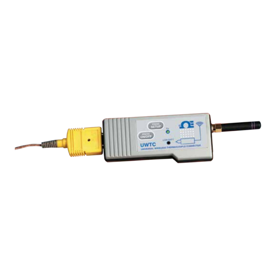
Transmitter Operation Section 4 – Transmitter/Connector Operation PRESS SETUP ® PRESS ON/OFF LOW BATT UWTC UNIVERSAL WIRELESS THERMOCOUPLE CONNECTOR Figure 4-1A. Thermocouple Connector (UWTC-1, UWTC-2) PRESS SETUP ® PRESS ON/OFF LOW BATT UWRTD UNIVERSAL WIRELESS RTD CONNECTOR (1) “ON/OFF” Button (2) “SETUP”... -
Page 31: Setup And Configuration
Connector Operation Industrial Probe (Thermocouple Versions) UWTC-NB9, UWTC-NB9-NEMA, UWTC-2-NEMA + TC INPUT NOT USED – TC INPUT Figure 4-2A. Thermocouple Version Industrial Probe (RTD Versions) RTD WIRING DETAIL UWRTD-NB9, UWRTD-NB9-NEMA, UWRTD-2-NEMA Figure 4-2B. RTD Version (1) “SETUP” Button (2) “ON/OFF” Button (3) Transmit Indicator (4) Battery Indicator (5) USB Port (6) Sensor Input 4.1 Setup and Configuration 4.1.1 Connecting your device... - Page 32 Connector Operation 4.1.2 Configure Your Connector/Transmitter Now that you have connected your USB cable to your PC and connector/ transmitter you will complete the following steps to configure your connector/ transmitter before placing the unit into operation. You will be using the configuration software utility that you installed onto your PC in Section 3.2.
-
Page 33: Setup Mode
Connector Operation RF Channel: Sets the channel number used for transmitting data to the receiver. Can be set in the for any value from 12 to 23. Network ID: Sets the ID of the network for the corresponding receiver. Receiver Address: Sets the address of the corresponding receiver. -
Page 34: Welcome To End Device Configuration Wizard
Connector Operation STEP 3. Programing your settings into a connector/transmitter. Figure 4-5. Welcome To End Device Configuration Wizard screen. After starting the setup utility program this will be the first screen you will see. Click the “Next >” button to proceed and continue setting up your connector/ transmitter. -
Page 35: Setup The End Device Screen
Connector Operation Figure 4-7. Setup The End Device Screen If you have not already placed your connector/transmitter into the “Setup” mode you should do this now before continuing. After your unit has been placed into the “Setup” mode click the “Next >” button to proceed and continue setting up your connector/transmitter. -
Page 36: Read Settings Screen
Connector Operation Figure 4-9. Read Settings Screen Figure 4-10. Choose Options Screen... -
Page 37: Send Settings To End Device Screen
Connector Operation From this screen you will select the main operating settings for your connector/transmitter. Start by selecting the type of Thermocouple you will be using. Then select the address setting for this unit. NOTE: Each connector/transmitter must have a different address number than other units in your system for proper operation). -
Page 38: Mounting, Installation And Antenna Connection
80.0 (3.15) MOUNTING SCREWS Figure 4-12A. Mounting Bracket Installation Figure 4-12B. Mounting Dimensions UWTC-1, UWTC-2, UWRTD-1, UWRTD-2 UWTC-2-NEMA, UWRTD-2-NEMA 4.2.2 Mounting When mounting your connector/transmitter, care should be taken to make sure it is as far away from any metal objects. If nearby metal gets too close... - Page 39 4.2.4 Antenna Connection Your device has been shipped to you a standard antenna already attached. You may remove and install Omega No. UWTC-ANT-LR high gain antenna to improve range and signal strength if needed. This antenna is sold as an accessory.
-
Page 40: Thermocouple Connections
Omega’s Miniature (SMP) Series and Standard (OST) Series of connectors will plug directly into the side of your unit. Omega’s line of thermocouple probes with connectors attached will also plug directly into your unit. -
Page 41: Rtd Connection
4.4 RTD Connection Your connector/transmitter has been designed with a RTD input that will interface with Omega’s TA4F connector. This connector will plug directly into the side of your unit as shown below. A mating connector was provided in the box with your unit (UWRTD-1, UWRTD-2 only). - Page 42 Figure 4-18B. Battery Placement UWTC-2-NEMA, UWRTD-2-NEMA Your NEMA transmitter is equipped with a “C” size lithium power cell assembly, Omega Part Number: UWTC-BATT-C. To install a replacement battery assembly, follow the steps outlined here. A. Remove the two screws that secure the main circuit board assembly.
- Page 43 Refer to the Omega technical data sheet or this manual for the temperature ranges over which the battery can be operated. Use of the battery outside this temperature range may damage the Transmitter or reduce the performance and life of the battery.
-
Page 44: Section 5 Receiver Operation
Operation is subject to the following two conditions: 1) This device may not cause harmful interference; 2) This device must accept any interference received, including interference that may cause undesired operation. OMEGA ENGINEERING, INC. omega.com Made in U.S.A. Stamford, CT 06907 Figure 5-1. Receiver Operation - UWTC-REC1... -
Page 45: Receiver Operation - Uwtc-Rec2-D
Pin#8 - Alarm Output (Open AMBIENT TEMPERATURE Drain to Pin#8, 10K 2.4 GHz ® pull-up toPin#7, UWTC-REC2-D SIDE VIEW OMEGA ENGINEERING, INC. Stamford, CT 06907 200 mA Max) omega.com Made in USA 12–16 Vdc Pin#9 - Analog Output (–) (6) Power LED... -
Page 46: Receiver Operation - Uwtc-Rec3
(3) Power LED (4) DC Power Jack POWER (5) Reset (6) Ethernet Connection (RJ45) TRANSMIT OMEGA UWTC SERIES 2.4 GHz Omega Engineering Inc. Stamford, CT 06907 omega.com Made in USA UWTC-REC3 SIDE VIEW DIAGNOSTICS NETWORK LINK ACTIVITY Figure 5-5. Receiver Operation - UWTC-REC3... -
Page 47: B Receiver Operation - Uwtc-Rec2-D-Tc-Nema
Receiver Operation Section 5 - Receiver Operation Cont. UWTC-REC2--D-TC-NEMA (1) Antenna (2) USB NEMA 4X Connector Sealing Cap (3) USB NEMA 4X Connector Cable (4) Indicator Lights (5) 8 Pin Analog I/O Waterproof Cable Cable Configuration: Orange Wire: Alarm Power Yellow Wire: Alarm Output Blue Wire: Digital Ground (6) Thermocouple Cable... -
Page 48: Receiver Operation - Uwtc-Rec4
Receiver Operation ANTENNA ANALOG JACK OUTPUT CONNECTOR POWER/ALARM CONNECTOR POWER LED 12-24 Vdc @ 250 mA RECIEVE LED + POWER SUPPLY STATUS LED – POWER SUPPLY STATUS STATUS Figure 5-6. Receiver Operation - UWTC-REC4 Figure 5-7. Power Supply Connection ANALOG OUTPUT - 4 (–) ANALOG OUTPUT - 4 (+) ANALOG OUTPUT - 3 (–) ANALOG OUTPUT - 3 (+) -
Page 49: Ma Output Example
Receiver Operation 4-20 mA ANALOG OUTPUT 0-5 Vdc ANALOG OUTPUT INTO PLC OR DATA LOGGER INTO PLC OR DATA LOGGER – – – 12 - 24 Vdc FROM HOST INSTRUMENT – STATUS STATUS 24 Vdc POWER SUPPLY Figure 5-10. 4-20 mA Output Example Figure 5-11. -
Page 50: Connecting Your Receiver To Your Pc
Receiver Operation 1N4004* – 0-24 VDC POWER – SUPPLY ALARM RELAY 300 mA MAX *DIODE REQUIRED FOR MAGNETIC RELAYS. NOT REQIRED FOR FOR SOLID STATE RELAYS, OR MAGNETIC RELAYS WITH INTERNAL DIODE. DRIVING A RELAY OR LOW IMPEDANCE INPUT (OPEN DRAIN) 0-24 VDC –... -
Page 51: A Rj45 Connector
Receiver Operation Ethernet Version (UWTC-REC3) The 10BASE-T Ethernet network (RJ-45) system is used in the UWTC-REC3 receiver for network connectivity. The 10 Mbps twisted-pair Ethernet system operates over two pairs of wires. One pair is used for receiving data signals. This means that four pins of the eight-pin connector are used. - Page 52 Receiver Operation The voltage on the Analog Output pin on the REC2 will correspond to the value of this sensor. Timeout: This setting is to indicate the number of seconds you want the REC2 to wait before displaying a NO SIGNAL message on the display. Process Units: Choose the units which will be used to set the limits of the analog output scaling.
-
Page 53: B Uwtc Rec2 Setup Screen
Receiver Operation REC2 Figure 5-15B. UWTC-REC2 Setup Screen REC4 Figure 5-15C. UWTC-REC4 Setup Screen 5-10... - Page 54 Receiver Operation 5-11...
- Page 55 Receiver Operation 5-12...
-
Page 56: Installation
Receiver Operation 5.2.2 Installation When installing your receiver it is important to position your device in such a way as to optimize the antenna location within what’s known as the “Fresnel Zone”. The Fresnel Zone can be thought of as a football-shaped invisible tunnel between two locations that provides a path for RF signals between your connector/transmitter and your receiver. - Page 57 Receiver Operation NOTES: 5-14...
-
Page 58: Section 6 System Operation
PRESS PRESS ON/OFF ON/OFF LOW BA TT LOW BATT UWTC UWTC UNIVERSAL WIRELESS THERMOCOUPLE CONNECTOR UNIVERSAL WIRELESS THERMOCOUPLE CONNECTOR Figure 6-1. Basic System Overview Up to 48 each of UWTC-1 or UWTC-2 connector/transmitters can be used with one UWTC-REC1 receiver. -
Page 59: Connector/Transmitter Operation
System Operation 6.4 Connector/Transmitter Operation 6.4.1 Button Operation (1.) “PRESS ON/OFF” The “PRESS ON/OFF” button on the front of your connector/transmitter is used to turn your unit “ON” or “OFF” (2.) “PRESS SETUP” The “PRESS SETUP” button on the front of your connector/transmitter is only used during the setup and configuration of your unit. -
Page 60: Receiver Operation
System Operation PRESS SETUP ® PRESS ON/OFF LOW BATT UWTC UNIVERSAL WIRELESS THERMOCOUPLE CONNECTOR Figure 6-3. Transmit and Low Battery Lights 6.5 Receiver Operation 6.5.1 Indicator Lights (1) Transmit (TX) Green Indicator Light The top green indicator light marked “TX” on the front of the receiver will only blink when the receiver is connected to your PC and you initialize your measurement software. -
Page 61: Environment/Operating Conditions
System Operation 6.6 Environment/Operating Conditions 6.6.1 Environment Omega’s UWTC or UWRTD series connector/transmitter and receiver unit has been designed to be fixed mounted and operated in a clean and dry indoor environment. Care should be taken to prevent the components of... -
Page 62: Determining And Maximizing Range
Position your receiver in a central location When multiple connector/transmitters are in operation, position your receiver unit in a central space if possible in equal distance to each connector transmitter. Figure 6-5. Determining Maximum Range STORAGE ROOM UWTC-1 CHAN 3 UWTC-2 CHAN 6 UWTC-2 CHAN 1... -
Page 63: Operation In Buildings
System Operation 6.7.1 Operation in Buildings Your Connector/Transmitter sends wireless data transmissions to a receiver connected to your PC. Radio signals are electromagnetic waves. A radio signal becomes weaker the further it travels. Range is decreased by different types of materials found in the direction of the signals propagation. -
Page 64: Antenna Basics
Operation is subject to the following two conditions: 1) This device may not cause harmful interference; 2) This device must accept any interference received, including interference that may cause undesired operation. OMEGA ENGINEERING, INC. omega.com Stamford, CT 06907 Made in U.S.A. 9–24 Vdc Figure 6-7. -
Page 65: Factory Preset Values
Figure 6-8. Vertical Antenna Placement transmitters and under normal operating conditions. For Version UWTC-1 or UWRTD-1 Transmit Time Estimated Battery Life 1 Sample/2 Seconds 12 days 1 Sample/3 Seconds... - Page 66 System Operation For UWTC-2, UWRTD-2, UWRH-2 Transmit Time Estimated Battery Life 1 Sample/2 Seconds 6 days 1 Sample/3 Seconds 9 days 1 Sample/5 Seconds 15 days 1 Sample/10 Seconds 30 days 1 Sample/15 Seconds 45 days 1 Sample/30 Seconds 90 days 1 Sample/45 Seconds 135 days 1 Sample/60 Seconds...
-
Page 67: Section 7 Troubleshooting
System. If the problems and solutions outlined here do not solve your problem, please contact Omega’s customer service department. Contact information can be found in Section 2 of this manual or by visiting omega. com. 7.1 Connector/Transmitter Troubleshooting... - Page 68 Troubleshooting Problem Solution If the problem persists a. Run the “End Device Configuration Wizard” after checking and (TC Central) with the device connected. correcting one or more b. When at the screen where all the settings appear, of the above conditions, click the “Copy to Clipboard”...
-
Page 69: Section 8 Service And Calibration
Service and Calibration Section 8 – Service & Calibration Your UWTC and UWRTD Series components have been built and factory calibrated to meet or exceed the specifications listed here in this manual. The following section provides information on how to have your device serviced and also on how to re-calibrate your unit in the field. -
Page 70: Section 9 Specifications
Specifications Section 9 – Specifications 9.1 Connector/Transmitter Specifications (Thermocouple Versions) Thermocouple (TC) Input UWTC-1, UWTC-2, J, K, T, E, R, S, B, C or N UWTC-2-NEMA: (User Field Selectable) UWTC-NB9: J, K, T, E, R, S, B, C or N... - Page 71 UWTC-1: 0dBm (1 mW) UWTC-2, UWTC-2-NEMA, UWTC-NB9: 10dBm (10 mW) Range of RF Link: UWTC-1: Up to 60 m (200') outdoor line of UWTC-1: sight. Up to 20 m (65') indoor/urban. UWTC-2, UWTC-2-NEMA, UWTC-NB9: Up to 120 m (400') outdoor line of sight. Up to 40 m (130') indoor/urban.
-
Page 72: Rtd Connector/Transmitter Specifications
0°C or above 400°C (752°F) RTD Measurement Resolution: 1°C/1°F Operating Environment: -10 to 70°C (14 to 158°F) RTD Connection UWRTD-1, UWRTD-2: Omega Series “T” receptacle. Use Omega Version TA4F mating connector (one included) UWRTD-2-NEMA, UWRTD-NB9: Integral Terminal Block Computer Interface:... -
Page 73: Uwtc-Rec1/Uwtc-Rec2 Receiver Specifications
Specifications UWRTD-2-NEMA, UWRTD-NB9: One Standard 3.6 V lithium Battery, 7.2 Ah capacity (C). Omega No: UWTC-BATT-C Battery Life: See Section 6 of this manual Data Transmitted to Host: RTD reading, connector ambient reading, RF transmit strength and battery condition Dimensions... -
Page 74: Uwtc-Rec4 Specifications
Specifications Output Scaling - Analog Output Accuracy: Mode Accuracy Resolution Range Scalable ±0.1% FS 8 uA 4 to 20.2 mA -1000 to +100000 Process Units ±0.2% FS 1 mV 0 to 5.05V -1000 to +100000 Process Units ±0.1% FS 1 mV 0 to 10.1V -1000 to +100000 Process Units... -
Page 75: Fcc (Domestic Use: Usa & Canada)
10.2 International Usage & CE Marking (Pending) The UWTC and UWRTD Series system components are CE marked and certified for use in several European countries. Please contact OMEGA for information on International Regulatory Compliance for each country. The single exception to this conformity is with the UWTC-REC2-TC receiver. -
Page 76: Patent Notice
UWTC/UWRTD Series 10.4 Patent Notice UWTC PATENT NOTICE (Product is covered by patents for Super MCJ, Uniconnector and pending wireless connector) PATENT NOTICE: U.S. PAT. NO. 6,074,089 / Canada 2,228,333 / UK GB 2,321,712 / Israel 123052 Other U.S. and international patents pending. 10-2... - Page 77 Department will issue an Authorized Return (AR) number immediately upon phone or written request. Upon examination by OMEGA, if the unit is found to be defective, it will be repaired or replaced at no charge. OMEGA’s WARRANTY does not apply to defects resulting from any action of the purchaser, including but not limited to mishandling, improper interfacing, operation outside of design limits, improper repair, or unauthorized modification.
-
Page 78: Data Acquisition
Where Do I Find Everything I Need for Process Measurement and Control? OMEGA…Of Course! Shop online at omega.com TEMPERATURE M U Thermocouple, RTD & Thermistor Probes, Connectors, Panels & Assemblies M U Wire: Thermocouple, RTD & Thermistor M U Calibrators & Ice Point References M U Recorders, Controllers &...