
Related Manuals for Omega MWTC SERIES


Summary of Contents for Omega MWTC SERIES
- Page 1 User’s Gui d e Shop online at omega.com e-mail: info@omega.com For latest product manuals: www.omegamanual.info MWTC/MWTC-D SERIES The Smart Connector Wireless Thermocouple/ Connector/ Transmitter/ Logger and Receivers...
- Page 2 Fax: (203) 359-7700 e-mail: info@omega.com For Other Locations Visit omega.com/worldwide The information contained in this document is believed to be correct, but OMEGA accepts no liability for any errors it contains, and reserves the right to alter specifications without notice.
-
Page 3: Table Of Contents
MTWC/MWTC-D Series - The Smart Connector Wireless Thermocouple/Connector/Transmitter/Logger & Receivers Table of Contents Section Page Section 1 Introduction ..................1-1 1.1 Precautions ....................1-1 1.2 Safety Warnings and IEC Symbols ............1-1 1.3 Product Labeling ..................1-2 1.4 Statement on FCC and CE Marking ............1-3 1.5 General Description &... - Page 4 MTWC/MWTC-D Series - The Smart Connector Wireless Thermocouple/Connector/Transmitter/Logger & Receivers Section 7 Troubleshooting ................. 7-1 7.1 Connector/Transmitter Troubleshooting ..........7-1 7.2 Receiver Troubleshooting ................ 7-1 7.3 LED Indications vs Operation ..............7-1 Section 8 Service and Calibration ..............8-1 8.1 Service and Calibration ................8-1 Section 9 Specifications ..................
- Page 5 MTWC/MWTC-D Series - The Smart Connector Wireless Thermocouple/Connector/Transmitter/Logger & Receivers Table of Figures Figure Description Page Section 1 Introduction Figure IEC Symbols ..................1-1 TC Connector Front Label ..............1-2 Connector Rear Label ................ 1-2 MWTC-REC1 Receiver Front and Rear Labels ......1-2 System Components ................
- Page 6 MTWC/MWTC-D Series - The Smart Connector Wireless Thermocouple/Connector/Transmitter/Logger & Receivers Section 4 Connector Operation Continued Figure Description Page Choose Options Screen ..............4-7 4-10 Data Logging Options Menu ............4-7 4-11 Typical Data File ................4-8 4-12 Send Settings to The Transmitter Screen ........4-9 4-12A LED Indications vs.
-
Page 7: Section 1 Introduction
Introduction Section 1 - Introduction Please read this manual completely before installing and operating your wireless connector/transmitter and receiver system. It’s important to read and follow all notes, cautions, warnings and safety precautions before operating this device. “Device” refers to your connector/transmitter or receiver unit. 1.1 Precautions •... -
Page 8: Product Labeling
1) This device may not cause harmful interference; 2) This device must accept any interference received, including interference that may cause undesired operation. PATENTS & PATENTS PENDING OMEGA ENGINEERING, INC. omega.com ® Stamford, CT 06907 Made in U.S.A. Figure 1-3. Connector Rear Label 1.3.3 MWTC-REC1 Receiver Front and Rear Labels... -
Page 9: Statement On Fcc And Ce Marking
It is the policy of OMEGA to comply with all worldwide safety and EMI/ ® EMC regulations that apply. OMEGA is constantly pursuing certification of its products to the European New Approach Directives. OMEGA will add the CE mark to every appropriate device upon certification. For additional information see Section 10 - Approvals & Regulatory Compliance. 1.5 General Description & System Components 1.5.1 General Description... -
Page 10: Section 2 Hardware
• 1 Connector/Transmitter • 1 Type-K Thermocouple Sensor (Omega No. SC-GG-K-30-36-PP) (MWTC models only) • 1 Standard (AAA) 1.5V Lithium Battery, (Omega No. MWTC-A-BATT) for use with Model MWTC. • 1 Mounting Bracket Kit • 1 Micro-B USB Cable for MWTC-D (Data Logger) With Model MWTC-REC1, MWTC-REC5, or MWTC-REC6 Receiver: •... -
Page 11: Section 3 Software
• Windows 2000, XP, Vista (32bit), or 7 Operating System 3.2.2 Software Installation Insert the MWTC Series User CD that was included with your receiver unit into the CD-ROM drive on your PC. Your system should begin the installation process automatically. If the software installation does not start automatically please see the “Troubleshooting”... -
Page 12: Select Install Screen
From this screen you select the folder were you want the program files installed on your PC. The default setting will install the software under your “Program” folders in a new folder named “Omega” To continue with installing the program click the “Next >” button. “Program” folders in a new folder named “Omega” To continue with installing the program click the “Next >”... -
Page 13: License Agreement Screen
Software From this screen you must select “Agree” to continue installing your program. After making your selection click the “Next >” button. The setup wizard will now install the software. Figure 3-4. License Agreement Screen Congratulations! You have just successfully installed the TC-Central Program on your PC. -
Page 14: Usb Driver Installation
Software 3.3 USB Driver Installation To install the USB software drivers that are required for your MWTC system components to operate correctly follow these procedures. NOTE: You need to have the TC-Central User Software CD that was supplied with your receiver loaded into the CD drive on your PC. - Page 15 Software Figure 3-7. Install Software Automatically Screen Next, check the “Install the software automatically” button. Then click the “Next>” button to continue. Figure 3-8. Completing The Found New Hardware Wizard Screen This screen will be displayed to indicate that the software drivers have been installed.
-
Page 16: Mwtc Connector/Transmitter Setup Utility Program
Software 3.4 MWTC Connector/Transmitter Setup Utility Program This utility is used to program your connector/transmitter for the following operating parameters: Channel Number, Sample Rate, and data logging (MWTC-D). For complete instructions on using this program please see Section 4. 3.5 TC-Central Measurement and Recording Program To launch the TC-Central program on your PC begin by accessing the “Programs”... -
Page 17: Channel Configuration
Software This is a partial view of the TC-Central Program in operation. You will not have any blocks receiving data until you have programmed and placed into operation your connector/transmitters. 3.5.2 Setting up the TC-Central Program Before you can make wireless measurements with your connector/transmitter the TC-Central software must be configured properly. The following steps outline how to setup your program. -
Page 18: Channel Display Box
Software ② Address Field Here you must set an address number into this box that corresponds to a matching Connector/Transmitter unit that you are using in your system. For the system to work correctly each Connector/Transmitter must have a number programmed that is different then other units in your system. Click with your mouse on the “Up”... - Page 19 Software codes have been set to the ANSI color codes. You can change these to IEC color codes, see section 3.5.2 Reference ② This location will display the reference name you typed into the “Description” field when this box was configured. This can be changed at any time Address ③ The number displayed here is the address number you specified when this display box was configured. This number must match the corresponding Connector/Transmitter that has the same number specified or your system will not receive the correct data readings.
-
Page 20: Charting Screen
Software 3.6 Chart Tab CHART TAB Figure 3-14. Chart TAB Menu Screen The “Chart” tab allows you to start, stop and view real-time data from the transmitters in a screen plot that you can save and print. Figure 3-15. Charting Screen Start Button ①... - Page 21 Software Line Color You can change the color specified for each channel’s line. Click the “Change” button to select a new color for the Channel selected. Interval The total logging time is displayed for the interval setting selected. In general, the interval should normally be set to a value equal to or greater than the same sample time you programmed into the corresponding connector/transmitter for that channel.
-
Page 22: Charting Options
Software 3.7 Charting Options You can access all of the charting options that are available by opening the chart option menu found under the “View” Tab. See below. Figure 3-17. Charting Options Screen Zoom In/Zoom Out Allow you to change the size of the chart on the screen. You can also use the Control-Up Arrow and Control-Down Arrow keys as well. - Page 23 Software Reset Axes will effectively cancel the results of a Data Zoom and return the axes back to their original dimensions, but will not change the size of the chart. Floating Cursor When checked, will display a crosshair type cursor that you can move with the mouse. You can use the Floating Cursor to pinpoint a particular temperature and time.
-
Page 24: Data Logging Screen
Software 3.8 Data Log Tab DATA LOG TAB Figure 3-18. Date Log TAB Screen The “Data Log” tab allows you to view received data from a connector/ transmitter in a table format as it is being recorded. This data can be saved and printed. - Page 25 Software Line Color You can change the color specified for each channel’s line. Click the “Change” button to select a new color for the Channel selected. Interval The total logging time is displayed for the interval setting selected. In general, the interval should normally be set to a value equal to or greater than the same sample time you programmed into the corresponding connector/transmitter for that channel.
-
Page 26: Menu Tabs
Software 3.9 Menu Tabs 3.9.1 File Menu Figure 3-21. File Menu Tab Open… Displays a dialog box which allows you to choose a data file to open and display on the chart and in the data log. This file must be a file that was saved by the Save menu item in TC Central. If the file has been modified externally, you may not be able to open it. Save… Displays a dialog box which allows you to save the data currently displayed on the chart and in the data log. The file format is (*.csv) (comma separated values), which can be opened by Microsoft Excel for further analysis and charting. It is strongly recommended that you do not modify this file, or you may not be able to open it again in TC Central. -
Page 27: View Menu Tab
Software Stop Data Logging… Performs the same function as the “Stop” buttons on the Chart and Data Log Tabs, by terminating any data logging/plotting session in progress. Export Chart… Displays a dialog box that allows you to either save an image of the current chart on the Chart Tab, or copy it to the clipboard. -
Page 28: Tools Menu Tab
Software Chart Performs the same functions as the Chart context menu. See Chart Tab Menu (Section 3.6) for an explanation of this menu. Data Log Performs the same functions as the “Auto Scroll Rows” checkbox and the “Adjust” button on the data log. See Data Log Menu (Section 3.8) for an explanation of these functions. - Page 29 Software Manual Connect Receiver Is available if you do not want TC Central to send “+++” to all of your serial ports. If you know the COM port number used by your receiver, you can connect to it from this menu without disturbing other COM ports. You can also use this menu to connect to a second receiver connected to the PC on a different COM port.
-
Page 30: Section 4 Transmitter/Connector Operation
Transmitter Operation Section 4 – Transmitter/Connector Operation Figure 4-1 shows the general dimensions. 15.2 82.5 (3.25) (0.6) 25.4 (1.0) FEMALE UNI-CONNECTOR ACCEPTS STANDARD MALE OSTW OR MINIATURE MALE SMPW MATING CONNECTIONS DIMENSIONS mm (in) MWTC-D USB PORT Figure 4-1. MWTC Overall Dimensions... -
Page 31: Setup And Configuration
Connector Operation 4.1 Setup and Configuration 4.1.1 Connecting Your Device Connect the USB programming cable to your connector/transmitter unit and also to an available USB port on your computer. See figures below. This cable was provided in the box with your receiver unit. For the MWTC-D, the USB cable is included with the transmitter. Simply connect the cable to the USB connector on the side of the transmitter (you do not need to open the unit) and into an available USB port on your PC, see Fig. - Page 32 Connector Operation 4.1.2 Configure Your Connector/Transmitter Now that you have connected your USB cable to your PC and connector transmitter you will complete the following steps to configure your connector/ transmitter before placing the unit into operation. You will be using the configuration software utility that you installed onto your PC in Section 3.2. If you have not installed the configuration software utility you should do so now. During this procedure you will be setting the following parameters in your connector transmitter.
-
Page 33: Setup Mode
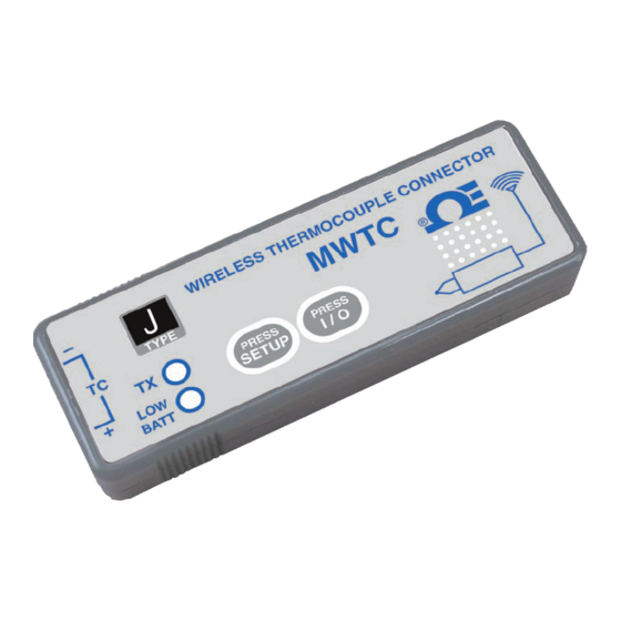
Connector Operation WIRELESS THERMOCOUPLE CONNECTOR – MWTC TYPE ® PRESS PRESS SETUP I / O BATT SETUP BUTTON ON/OFF BUTTON Figure 4-3. Setup Mode Press and hold the “ON/OFF” button. While the “ON/OFF” button is being held, press the “SETUP” button one time and then release the “ON/OFF” button. -
Page 34: Welcome To Universal Wireless Screen
Connector Operation STEP 3. Programing your settings into a connector/transmitter. Figure 4-5. Welcome To Universal Wireless Screen After starting the setup utility program this will be the first screen you will see. Click the “Next >” button to proceed and continue setting up your connector/ transmitter. Each screen will provide instruction details on how to proceed. Figure 4-6. -
Page 35: Connect The Transmitter Screen
Connector Operation Figure 4-7. Connect The Transmitter Screen If you have not already connected your connector/transmitter to a USB port on your PC you must do this now before continuing. After your unit has been connected click the “Next >” button to proceed and continue setting up your connector/transmitter. -
Page 36: Choose Options Screen
Connector Operation Figure 4-9. Choose Options Screen From this screen you will select the main operating settings for your connector/ transmitter. Start by selecting the address setting for this unit. (Note: Each connector/transmitter must have a different address number than other units in your system for proper operation). Then select the sample rate that your unit will transmit data to the receiver. -
Page 37: Data Logging Options Menu
Connector Operation Figure 4-10. Data Logging Options Menu Figure 4-11. Typical Data File... - Page 38 Connector Operation Figure 4-12. Send Settings To Transmitter Screen Congratulations! You have successfully programmed your connector transmitter. After your unit has been programmed click the “Finish” button to close the utility program or click the “Start” button to begin setting up a second unit. You can now disconnect your connector transmitter from the programming cable.
-
Page 39: Mounting, Installation And Antenna Connection
Connector Operation Here is a Figure 4-12A showing the operation status vs. the LED indications for MWTC-D: Operation Status LED Indications Open Sensor Input Red LED blinks immediately after every Green LED blink Wireless Transmission, Green LED blinks every transmission interval when pressing I/O key Logging Mode, Red LED blinks once, then the Green LED... -
Page 40: Mounting Bracket Installation
Connector Operation NOTE: TIP: Use the plate as a template to mark the location of the mounting holes you need to drill before installing the mounting kit onto the connector transmitter. MOUNTING MOUNTING SCREW BRACKET SPACER MWTC UNIT I / 0 Figure 4-13. - Page 41 Connector Operation In order to achieve maximum range, the football-shaped path in which radio waves travel must be free of all obstructions. Obstacles in the path (especially metal) will decrease the communication range between your connector/ transmitter and receiver. Also, If the antennas are mounted just barely off the ground, over half of the Fresnel zone ends up being obstructed by the earth resulting in significant reduction in range. To avoid this problem, the antennas should be mounted high enough off of the ground so that the earth does not interfere with the central diameter of the Fresnel zone.
-
Page 42: Thermocouple Connections
Omega’s Miniature (SMP) Series and Standard (OST) Series of connectors will plug directly into the side of your unit. Omega’s line of thermocouple probes with connectors attached will also plug directly into your unit. -
Page 43: Battery Installation Or Replacement
Connector Operation SAFE THERMOCOUPLE AMBIENT AREA MEASUREMENT AREA CONNECTOR/TRANSMITTER WIRELESS THERMOCOUPLE CONNECTOR – MWTC TYPE ® PRESS PRESS SETUP I / O BATT THERMOCOUPLE PROBE MATING CONNECTOR Figure 4-16. Recommended Thermocouple Placement CAUTION: Installing your connector/transmitter in an application were the device will be exposed to ambient temperatures above or below the operating limits specified in this manual will damage your unit and cause the unit to malfunction and produce incorrect operation. - Page 44 Refer to the Omega technical data sheet or this manual for the temperature ranges over which the battery can be operated. Use of the battery outside this temperature range may damage the MWTC Transmitter or reduce the performance and life of the battery.
-
Page 45: Section 5 Receiver Operation
① Antenna ② USB Port (mini-B) ③ Indicator Lights USB RECEIVER MWTC SERIES WIRELESS RECEIVER ® Figure 5-1. Receiver Operation - Model MWTC-REC1 5.1 Mounting, Installation 5.1.1 Mounting A mounting bracket was included with included with your receiver. The diagram below shows dimensions and mounting hole location. Rubber bumpers have also been supplied with your receiver should you wish to use the device on a desk or a work bench next to your PC. -
Page 46: Mounting
Receiver Operation 3.2 (0.125) DIA. 2 PLACES MWTC SERIES WIRELESS RECEIVER 23 (0.87) ® 79 (3.12) DIMENSIONS mm (in) Figure 5-2. Mounting 5.1.2 Installation When installing your receiver it is important to position your device in such a way as to optimize the antenna location within what’s known as the “Fresnel Zone”. -
Page 47: Section 6 System Operation
Based on the physical principle of the propagation of radio waves, certain basic conditions should be observed. The following simple recommendations are provided to insure proper installation and correct operation of your MWTC Series system. 6.2 RF Communication Basics The Model MWTC wireless Thermocouple Connector/Transmitter sends wireless transmissions to the MWTC-REC1, MWTC-REC5, or MWTC-REC6 receiver. -
Page 48: Connector/Transmitter Operation
System Operation 6.4 Connector/Transmitter Operation 6.4.1 Button Operation (1.) “PRESS ON/OFF” The “PRESS ON/OFF” button on the front of your connector/transmitter is used to turn your unit “ON” or “OFF” (2.) “PRESS SETUP” The “PRESS SETUP” button on the front of your connector/transmitter is only used during the setup and configuration of your unit. See Section 4.1.2 for more information. -
Page 49: Receiver Operation
SETUP I / O BATT Figure 6-3. Transmit and Low Battery Lights 6.5 Receiver Operation 6.5.1 Indicator Lights USB RECEIVER MWTC SERIES WIRELESS RECEIVER ® Figure 6-4. Indicator Lights ① Power (PWR) Green Indicator Light ② Transmit/Receive (TX) Red Indicator Light The red indicator light marked “TX”... -
Page 50: Environment/Operating Conditions
System Operation 6.6 Environment/Operating Conditions 6.6.1 Environment Omega’s MWTC series connector/transmitter and receiver unit has been designed to be fixed mounted and operated in a clean and dry indoor environment. Care should be taken to prevent the components of your wireless system from being exposed to moisture, toxic chemicals and extreme cold or hot temperature that are outside the specifications listed in this manual. -
Page 51: Determining And Maximizing Range
System Operation 6.7 Determining and Maximizing Range NOTE: The available maximum range specified for the wireless Series system in this manual is only achievable under optimum installation conditions. Mounting height, obstructions in your “Fresnel Zone” and ambient conditions can cause a decrease in signal strength resulting in a shorter range between your transmitter/connector and receiver unit. -
Page 52: Operation In Buildings
System Operation 6.7.1 Operation in Buildings Your Connector/Transmitter sends wireless data transmissions to a receiver connected to your PC. Radio signals are electromagnetic waves. A radio signal becomes weaker the further it travels. Range is decreased by different types of materials found in the direction of the signals propagation. Radio waves can penetrate most types of wall materials, but they are dampened more than they would be by a direct line-of-sight installation. -
Page 53: Antenna Basics
System Operation 6.8 Antenna Basics 6.8.1 Antenna Basics By definition, an antenna is a device used to transform an RI signal, traveling on a conductor, into an electromagnetic wave in free space. Antennas demonstrate a property known as reciprocity, this means that an antenna will always maintain the same characteristics regardless if it is used to transmit or receive. Most antennas are resonant devices, which means they operate efficiently over a relatively very narrow frequency band. -
Page 54: Factory Preset Values
Many factors such as ambient temperature conditions and transmitting rate can have a big effect on the life of the battery used in your connector/transmitter. Transmitting data places MWTC SERIES WIRELESS RECEIVER ® a big demand of the battery in your connector/ transmitter. The transmit rate is the single most contributing factor in the life of your battery. -
Page 55: Section 7 Troubleshooting
System. If the problems and solutions outlined here do not solve your problem, please contact Omega’s customer service department. Contact information can be found in Section 2 of this manual or by visiting omega.com. 7.1 Connector/Transmitter Troubleshooting Problem Solution 1. -
Page 56: Led Indications Vs Operation
Troubleshooting Operation Status LED Indications Open Sensor Input Red LED blinks immediately after every Green LED blink Wireless Transmission, Green LED blinks every transmission interval when pressing I/O key Logging Mode, Red LED blinks once, then the Green LED when pressing I/O key blinks every recording interval Wireless &... -
Page 57: Section 8 Service And Calibration
Service and Calibration Section 8 – Service & Calibration Your MWTC Series components have been built and factory calibrated to meet or exceed the specifications listed here in this manual. The following two sub- sections provide information on how to have your device serviced and also on how to re-calibrate your unit in the field. 8.1 Service & Calibration If any of your wireless system components require service or calibration, please call our Customer Service Department at 1-800-622-2378 or 203-359-1660. -
Page 58: Section 9 Specifications
Specifications Section 9 – Specifications 9.1 Connector/Transmitter Specifications (Thermocouple Models) Thermocouple Types: J, K, T, E, R, S, B, C or N (Factory Set) Thermocouple J: -100 to 760°C (-148 to 1400°F) Measurement Range: K: -100 to 1260°C (-148 to 2300°F) T: -200 to 400°C (-328 to 752°F) E: -200 to 1000°C (-328 to 1832°F) R: 260 to 1760°C (500 to 3200°F) -
Page 59: Receiver Specifications
Specifications Battery: One 1.5 V lithium, 1200 mA capacity (AAA) (included), also works with 1.5V alkaline and 3.6V lithium Battery Life (Typical): 7.2 months at 1 sample/minute reading rate @25°C (77°F) Data Transmitted to Receiver: Thermocouple reading and connector ambient reading, and battery voltage Dimensions: 82.5 L x 25.4 W x 15.2 H mm (3.25 x 1 x 0.6") -
Page 60: Fcc (Domestic Use: Usa & Canada)
Approvals, Regulatory Compliance & Patent Notice Section 10 – Approvals, Regulatory Compliance & Patent Notice NOTE: All approvals outlined in this manual are based on testing that was done with antennas that are supplied with your wireless Series System Components. Removing and or installing a different antenna will void the product compliance demonstrated in these documents. -
Page 61: International Usage & Ce Marking (Pending)
Transmitting Power Your MWTC Series System Components have been designed and manufactured so that the transmitting power will not exceed 10 dBm (10 mW). 10.3 Declaration of Conformity (DOC) Contact OMEGA for status on CE marking and DOC availability. - Page 62 MTWC/MWTC-D Series - The Smart Connector Wireless Thermocouple/Connector/Transmitter/Logger & Receivers NOTES: 10-3...
- Page 63 Department will issue an Authorized Return (AR) number immediately upon phone or written request. Upon examination by OMEGA, if the unit is found to be defective, it will be repaired or replaced at no charge. OMEGA’s WARRANTY does not apply to defects resulting from any action of the purchaser, including but not limited to mishandling, improper interfacing, operation outside of design limits, improper repair, or unauthorized modification.
- Page 64 Where Do I Find Everything I Need for Process Measurement and Control? OMEGA…Of Course! Shop online at omega.com TEMPERATURE M U Thermocouple, RTD & Thermistor Probes, Connectors, Panels & Assemblies M U Wire: Thermocouple, RTD & Thermistor M U Calibrators & Ice Point References M U Recorders, Controllers &...