Table of Contents
Advertisement
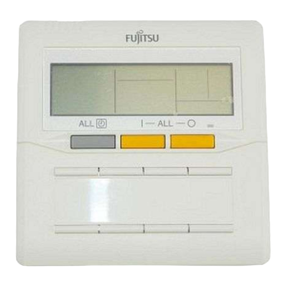
Group Remote Controller (UTB- * D * )
INSTALLATION INSTRUCTION SHEET
(PART NO. 9374707034)
For authorized service personnel only.
CONTENTS
SAFETY PRECAUTIONS ............................................... 1
STANDARD PARTS ........................................................ 2
FLOW OF INSTALLATION .............................................. 2
INSTALLATION ............................................................... 3
SETTING ......................................................................... 5
• EXPLANATION OF TERMS ......................................... 5
• NAME OF PARTS ......................................................... 6
SAFETY PRECAUTIONS
G Before using the appliance, read these "SAFETY PRECAUTIONS" thoroughly and operate in the correct way.
G The instructions in this section all relate to safety; be sure to maintain safe operating conditions.
This mark indicates procedures which, if improperly performed, might lead to the death or serious
WARNING
injury of the user.
G
For the air conditioner to operate satisfactorily, install
it as outlined in this installation instruction sheet.
G
Do not turn on the power until all installation work is
complete.
Let the customer keep this installation instruction sheet because it is needed when the air conditioner or remote controller is
serviced or moved.
This mark indicates procedures which, if improperly performed, might possibly result in personal harm
CAUTION
to the user or damage to property.
G
Do not wire the remote controller cord and the bus
wire together with or parallel to the connection ca-
bles, transmission cords, and power supply cords
of the indoor and outdoor units. It may cause erro-
neous operation.
G
Do not expose the controller directly to water.
G
Do not operate the controller with wet hands.
G
Do not touch the switches with sharp objects.
G
Always turn off the electrical breaker whenever
cleaning the controller, the air conditioner or the
air filter.
• TURN ON THE POWER ............................................... 7
• SETTINGS .................................................................... 7
• REMOTE CONTROLLER SETTINGS .......................... 8
• INDOOR UNIT REGISTRATION ................................ 11
• FINAL STEP ............................................................... 13
• ERROR CODE ........................................................... 14
G
Installation work must be performed in accordance with
national wiring standards by authorized personnel only.
G
Check the condition of the installation stand for
damage.
G
Ensure that any electronic equipment is at least
one meter away from the controller.
G
Avoid installing the controller near a fireplace or
other heating apparatus.
G
When installing the controller, take precautions to
prevent access by infants.
G
Do not use inflammable gases near the controller.
En-1
Advertisement
Table of Contents

Related Manuals for Fujitsu UTB-YDB


Summary of Contents for Fujitsu UTB-YDB
-
Page 1: Table Of Contents
Group Remote Controller (UTB- * D * ) INSTALLATION INSTRUCTION SHEET (PART NO. 9374707034) For authorized service personnel only. CONTENTS SAFETY PRECAUTIONS ..........1 • TURN ON THE POWER ..........7 STANDARD PARTS ............2 • SETTINGS ..............7 FLOW OF INSTALLATION ..........2 •... -
Page 2: Standard Parts
STANDARD PARTS The following installation parts are supplied. Use them as required. Name and Shape Application Name and Shape Q’ty Application Q’ty Group remote Use for air conditioner Tapping screw For installing the remote (M4 × 16 mm) controller operation controller Binder For remote controller... -
Page 3: Installation
INSTALLATION 1. SPECIFICATION Unit: mm (in.) 33.5 (1-3/16) (1-5/16) 120 (4-3/4) (29/32) Hole (11/16) (11/32) 4.5 (3/16) (1/4) Hole × 2 Hole × 3 When connecting the Group remote controller and Convertor, use the following wiring. Size Wire type Remarks Remote controller cord 0.33 mm (AWG22) - Page 4 3. INSTALLING THE REMOTE CONTROLLER CAUTION • Do not touch the group remote controller Circuit board and Circuit board parts directly with your hands. • When working with the wiring, be careful not to scratch or damage the wires. Open the operation panel on the front of the remote controller, Fig.
-
Page 5: Setting
SETTING EXPLANATION OF TERMS Remote System controller group Refrigerant system Refrigerant pipe Indoor unit Wireless remote Wired remote Group remote controller controller controller Outdoor unit Convertor Transmission line Controller line Controller related items G System: This is all of the indoor units, outdoor units and controller units connected by the same transmission line. G Refrigerant system: [Not for J-series*] This is a system composed of indoor and outdoor units connected by the same refrigerant pipe. -
Page 6: Name Of Parts
NAME OF PARTS G With cover closed Indoor Unit Operation Indicators Operation Lamp ALL OFF Button ALL ON Button ALL TIMER Button ON/OFF Button Indoor Unit Name Labels G With cover open Timer and Clock Displaying the Status Display and setting and Controlling indoor units Transmission Display... -
Page 7: Turn On The Power
TURN ON THE POWER Turn on the power Once the installation and wiring has been completed, use the following procedure to turn on the power. 1. Turn on the power for all connected indoor units. 2. Turn on the power for all connected outdoor units. 3. -
Page 8: Remote Controller Settings
REMOTE CONTROLLER SETTINGS Remote Controller Settings Initial Screen Remote Controller Settings G To select the setting : Setting the Group remote controller address → Page 8 Settings : Forbidden → Page 9 : Time Display Settings → Page 9 : Timer Operation Settings → Page 9 Press the DAY button to select the item to be set. - Page 9 Forbidden To move to the following settings Forbidden Press the DAY button to move to “ Time Display Settings. ” Forbidden Press the DAY button to move to “ Setting the Group remote controller address. ” Time Display Settings (This switches the time display.) To switch the time display Decrement Increment Check that it is...
- Page 10 Temperature Range Settings (This changes the temperature range.) To set the temperature range Decrement Increment Check that it is Press the Set Time buttons to set the temperature range. Temperature range setting G The temperature range set for heating operation is different. : 10 °C –...
-
Page 11: Indoor Unit Registration
INDOOR UNIT REGISTRATION G A maximum of 8 remote controller groups can be registered for a Group remote controller. G Remote controller groups in 2 different refrigerant systems that are connected to a single convertor can be registered. G The remote controller groups registered can be monitored and controlled. G When registering indoor units to each of the buttons, consult the customer. - Page 12 When a remote controller group made up of multiple indoor units is registered, the remote controller address and the indoor unit address are selected. G Remote controller address selection Refrigerant circuit address Indoor unit address G Indoor unit address selection ex.: Refrigerant circuit address “...
-
Page 13: Final Step
Moving to “ REMOTE CONTROLLER SETTINGS” To set the remote controller Press the Set Temperature button seven times or press the Pressing seven times moves Set Temperature button once to move to remote controller to remote controller settings settings. Pressing once moves to remote controller settings Completing All of the Settings To complete Settings... -
Page 14: Error Code
ERROR CODE The air conditioning system must be inspected if “E✽:✽✽” (error code) appears on the Timer and Clock Display, or the operation lamp is flashing. The following explains the meaning of each of the error codes. Model code : Outdoor unit Model code : Indoor unit : Group remote controller...