
Related Manuals for 3M Peltor DECT-Com II


Summary of Contents for 3M Peltor DECT-Com II
- Page 1 Peltor DECT-Com II Full Duplex Wireless Intercom Instruction Manual...
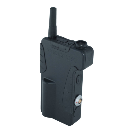
- Page 2 Switch DECT-Com II unit on as base or with a connected auxiliary equipment. [M] & [–] Switch DECT-Com II unit on as portable Press twice to talk in conference 3 [PTT1] Manually transmit in DECT-Com conference 1 Press once to listen in conference 3 Press twice to talk in conference 1 Press once to listen in conference 1 [+] & [–] All call (simplex transmission) For latest revised full user’s instructions, please see www.3m.com/peltorcomms on the Internet. Look in section “Rest of the world” and find “PDF LIBRARY”, where you can read or download multilingual information about the 3M Peltor DECT-Com II system. Antenna Function indication ring Headset connector [M] Mode LED (Light Emitting Diode) Clip [+] Up [–] Down PTT1 Push-To-Talk 1 PTT2 Push-To-Talk 2 PTT3 Push-To-Talk 3 (Fig.
-
Page 3: Table Of Contents
POWER SUPPLY 6.1 Internal Batteries 6.2 External Batteries 6.3 Fixed Mounted Power Supply 6.4 Mains Adapter ANTENNAS 7.1 General Antenna 7.2 Omnidirectional Vehicle Antenna EXTERNAL EQUIPMENT 8.1 External Equipment PELTOR DECT-Com II UNITS 9.1 MAIN UNITS, SPECIAL 1.9 GHz VERSION 9.2 ACCESSORIES AND SPARE PARTS 10 TECHNICAL DATA OF MAIN UNIT 11 APPROVALS 12 WARRANTY 13 PROGRAMMING DECT-Com II UNITS 14 DECLARATION OF CONFORMITY 15 VOICE MESSAGES... -
Page 4: Introduction
2.1 PREPAIRING THE MAIN UNIT Open the main unit box. Mount one of the three antenna rings on the antenna connector. The indication rings should be used to seal the antenna; green color for portable units, red for base units or black for “discrete” use. NOTICE! The ring should be turned correctly to fit on the screw nut! Screw the antenna tightly on top of the ring. Mount the battery in the battery compartment and close the lid with the screw. Mount the attachment clip on the back of the unit. Turn it to the tagged end down! To charge the battery, place the unit in a charger/holder. 2.2 PELTOR DECT-Com II SYSTEM 2.2.1 MAIN UNITS, GENERAL 1.9 GHz DC2911 1.9 GHz portable unit DC2912 1.9 GHz base/portable unit DC2915 1.9 GHz Ext. base/portable unit 2.3 SWITCHING A MAIN UNIT ON AND OFF • Switch a DECT-Com II main unit on by pressing the [M] button. -
Page 5: Main Units
The Sound Solution 2.4 BASE/PORTABLE UNIT 2.4.1 SWITCHING A BASE/PORTABLE UNIT ON • Switch a base unit on by pressing the [M] button. In a headset, connected in the headset connector on the unit, a voice confirmation “BASE, POWER ON” is given and the LED (light emitting diode) is flashing, showing that the base unit is setting up the system. Notice: Initially, a base/portable unit is starting up as a base. (See also ALTERNATIVE OPERATION MODES OF BASE/PORTABLE UNITS below.) After approximately 20 seconds, the system is ready and a voice message “GROUP 1” is given. The LED on the unit is flashing slower, showing that the base unit is ready for use and portable units can be logged on. (The LED can be switched off with use of special DECT-Com II software.) 2.4.2 SWITCHING A BASE/PORTABLE UNIT OFF • Switch a base unit off by pressing and holding the [M] button for approximately 2 seconds. A voice confirmation “POWER OFF” is given, the LED is unlit, and the unit is turned off. 2.4.3 ALTERNATIVE OPERATION MODES OF BASE/PORTABLE UNITS By different start-up sequences the base/portable main units can be set up to work either as a base or as a portable unit. - Page 6 Notice: All main units are delivered open for registration from factory and a DECT-Com II system can be started directly “out of the box” by first starting a base/portable unit as a base as described above and after that, all portable units, sequentially and continually, as described above. After the first turn off of the base unit, the configuration of the system is fixed and all future change of any units has to be handled by your Authorized Peltor DECT-Com II Dealer*). If your system is delivered pre-registered in a certain configuration by your Authorized Peltor DECT-Com II Dealer*, all future registration also has to be handled by your Authorized Peltor DECT-Com II Dealer*). 2.5 PORTABLE UNIT 2.5.1 SWITCHING A PORTABLE UNIT ON • Switch the portable unit on by pressing the [M] button. In a headset, connected in the headset connector on the unit, a voice confirmation “POWER ON” is given and the LED on the unit is flashing green, showing that the unit is logging on to the base. When the unit is ready for use, a voice message “BASE #1, GROUP #1” is given and the LED is steady green. Notice: All portable units normally start in listen only mode in group 1. At first start up a voice message “SEARCHING” is given. When a base is found a voice message BASE (number), GROUP 1” is given. When restarting a portable unit, which is programmed to be able to work with more than one base, it will try to log on to the last us ed base.
- Page 7 2.5.5 LOGGING ON A NEW PORTABLE UNIT TO A BASE If another portable unit shall be logged on to the base, the actual base unit must be set in REGISTRATION mode (see 2.1.4). The portable unit must be in SEARCH mode (see 2.2.7). Notice: All main units are delivered open for registration from factory and a DECT-Com II system can be started directly “out of the box” by first starting a base/portable unit as a base as described above and after that, all portable units, sequentially and continually, as described above. After the first turn off of the base unit, the configuration of the system is fixed and all future change of any units has to be handled by your Authorized Peltor DECT-Com II Dealer*.) If your system is delivered pre-registered in a certain configuration by your Authorized Peltor DECT-Com II Dealer*, all future registration also has to be handled by your Authorized Peltor DECT-Com II Dealer*). 2.5.6 SEARCHING A BASE FROM A PORTABLE UNIT • In BASE SELECTION mode on a portable unit; double press on the [M] button to enter BASE SEARCH mode. A voice confirmation “SEARCHING” is given repeatedly, confirming that the unit is searching for active bases in range. When a base is found a voice confirmation “BASE (number), GROUP 1” is given.
-
Page 8: Autotalk
3.3 LOGGING IN AS AN ACTIVE CONFERENCE MEMBER IN ANOTHER CONFERENCE GROUP • Press on another [PTT #] button to become a member in another conference. A tone is confirming that you are a member in the selected conference. 3.4 AUTOTALK A system for maximum 9 users can be programmed in a configuration where all the portables always should be in TALK MODE. Automatic talk mode makes it possible to ensure that all the members in the small group are speakers in the conference as soon as they are in range of the base unit. (For further information; contact your Authorized Peltor DECT-Com II Dealer*).) 4 CONTROLS 4.1 MODE The mode button [M] controls functions of the unit. • Step forward through the MENU mode steps by pressing briefly on the [M] button. Voice messages “VOX”, “MICROPHONE”, “VOLUME” are given respectively to confirm the actual mode. • Step backwards through MENU mode steps by double press on the mode button. Voice messages “MICROPHONE”, “VOX”, “VOLUME” are given respectively to confirm the actual mode. • Use the [+] and [–] buttons to adjust the settings respectively. Current settings are stored when the unit is switched off. Notice: A double-press in VOLUME mode and LISTEN ONLY mode on a base unit will put the unit in REGISTRATION mode (see 2.1.4). Double press in VOLUME mode and LISTEN ONLY mode on a portable unit will put the unit in BASE SELECTION mode (see 2.2.6). -
Page 9: Controls
The synchronisation should be done by starting the systems in range of each others. If this function should always be accessible, the bases have to constantly be in range (for instance as fixed mounted bases). If the bases have been out of range of each others, it may take up to 20 minutes to get them synchronised again! • Press and hold UP [+] and DOWN [–] buttons simultaneously to transmit a short message. A double tone is confirming that the ALL-CALL is activated. The transmission period is limited, normally to max. 30 seconds. 4.4 LOCKED BUTTONS To avoid unwanted changes in the settings of functions, it is possible to lock all buttons, so that only the ON/OFF function is active. This can preferably be combined with the automatic talk mode function. (See also AUTOTALK above.) Notice: Many of the functions and settings in DECT-Com II can be adjusted according to the user’s demands. For further information; contact your Authorized Peltor DECT-Com II Dealer*). 5 OUT OF RANGE Peltor DECT-Com II is a short range communication system. (See TECHNICAL DATA OF MAIN UNIT below.) If the portable unit is close to the actual maximum working range from the base unit, a voice message “SIGNAL LOW“is given in the connected headset. When the portable unit is out of range from the base unit, a voice message “SIGNAL LOW, OUT OF RANGE is given in the connected headset. After another 20 seconds, the may try to find another base and a voice message “SEARCHING” is given. When the portable unit is in range again, or another base is found, a voice message “BASE (number)” is given in the connected headset. If automatic talk mode function is activated, a portable unit, after being out of range, always return to TALK MODE as soon as it is in... -
Page 10: Power Supply
6 POWER SUPPLY A main unit can generally be powered from a rechargeable battery pack DC2033. The external battery carrier DC2032, for 6 or 3 type AA batteries, can also be used to increase the usage time of the unit. Also, a main unit can be continuously power supplied in a power supply holder DC2068. 6.1 INTERNAL BATTERIES 6.1.1 BATTERY PACK The main units require a special Peltor battery pack DC2033. 6.1.2 CHANGING THE INTERNAL BATTERY PACK • Switch the unit off by pressing and holding the [M] button for approximately 2 seconds. A voice confirmation “POWER OFF” is given and the LED is turned off. Turn the clip aside and loosen the screw with a suitable tool (see figure 1). (n Warning: Do not use your nail! It may break.) Open the battery lid and replace the battery (see fig. 2). Push the battery pack down firmly to get the connecting plates in contact with the pins (see fig. 3). Hook the battery lid on to the bottom of the unit, close it, press down and tighten the screw again with the tool (see fig. 4). (n Warning: Do not use your nail! It may break.) n The message “BATTERY LOW” indicates that the energy in the battery is low and you should change or charge battery as soon as possible. n The message “BATTERY EMPTY” indicates that the energy in the battery is very close to empty and the unit will automatically switch off! 6.1.3 CHARGING AN INTERNAL BATTERY PACK A rechargeable NiMH-battery DC2033 has to be charged in a main unit with an appropriate Peltor charger/holder. -
Page 11: Fixed Mounted Power Supply
6.3.1 AUTOMATIC RESTART OF A BASE UNIT With the Connector Sealing Plug DC2078 it is possible to have a base unit, which is placed in a power supply DC2068, automatically restarted after a power failure. Instead of a headset in the connector on top of the base unit, the “arm” of the connector sealing plug is pressing on the “MODE” button of the main unit, enabling automatic restart after shorter power outages. 6.4 MAINS ADAPTER There is also a separately sold mains adapter DC2061, with exchangeable European, UK and US type mains connectors, for the input of 100 - 240 Volt AC, 50/60 Hz. It may replace a faulty mains adapter for a charger/holder DC2064 or a power supply/holder DC2068. (It may also be used with a programming charger/holder DC2065, but which is only available for Authorized Peltor DECT-Com II Dealers.) 7 ANTENNAS 7.1 GENERAL ANTENNA A DECT-COM II main unit normally works with one of two antennas; one internal on the printed circuit board and one external antenna, mounted in a connector on top of the unit. The external antenna DC2041, which is delivered with all DECT-Com II main units, should normally be mounted on the main unit together with a plastic ring (see UNIT FUNCTION INDICATORS below). 7.1.1 UNIT FUNCTION INDICATORS A package DC2048 with 3 differently coloured plastic rings is enclosed in the box of each DECT-Com II main unit. The rings are meant to seal around the antenna connector, but also to indicate the function of the unit; for instance a red ring for a base unit, a green ring for a portable unit and a black ring for an “other” unit. 7.2 OMNIDIRECTIONAL VEHICLE ANTENNA If a base unit is placed inside a vehicle, the omnidirectional antenna DC2046, with magnetic foot, can replace the external antenna DC2041 to improve communication with portable units outside of the vehicle. Contact your Authorized Peltor DECT-Com II Dealer*) for the following options! -
Page 12: Antennas
8 EXTERNAL EQUIPMENT 8.1 EXERNAL EQUIPMENT The Extension Base/Portable unit DC2815 is equipped with a connector for connecting external equipment, like communication radios, telephones etc. In the list of PELTOR DECT-Com II PRODUCTS (see below) you will find adapter cables for the most common communication radios, a general telephone cable and a cable for ground mechanic. 9 PELTOR DECT-Com II UNITS 9.1 MAIN UNITS, GENERAL 1.9 GHz DC2911 1.9 GHz portable unit DC2912 1.9 GHz base/portable unit DC2915 1.9 GHz Extension base/portable unit 9.2 ACCESSORIES AND SPARE PARTS DC2031 Battery lid for use with 3xAA standard batteries in main unit. DC2032 Battery carrier for 6xAA auxiliary batteries (excl. batteries). DC2033 Rechargeable NiMH-accumulator (2100 mAh) -
Page 13: Technical Data Of Main Unit
The Sound Solution 10 TECHNICAL DATA OF MAIN UNIT UPCS Frequency range: 1920 – 1930 MHz Operation mode: Duplex Output power: Max. 250 mW, average 10 mW (portable) / 120 mW (base) Current consumption: Base/Portable unit as base typ. 320 mA (4 portables system) DC2812, DC2815 as portable; typ. 160 mA in talk mode Portable unit DC2811 40 mA (listen only) / 60 mA (talk mode) Working range: Outdoors typ. 250 m (line of sight) Indoors typ. 50 m Battery life cycle: With rechargeable battery approx. 6 h (base unit) Peltor DC2033 approx. 40 h (portable unit) With 6xAA additional 2100... -
Page 14: Approvals
13 PROGRAMMING DECT-Com II UNITS Special software and a programming holder are available for customizing several functions in the DECT-Com II system. Contact your Authorized Peltor DECT-Com II Dealer*) for further information! 14 DECLARATION OF CONFORMITY A copy of the Declaration of Conformity (in English) is found on the last pages of this user’s manual. *) For address to your nearest Authorized Peltor DECT-Com II Dealer, contact your 3M office! **) For address to your nearest Peltor Repair Center, contact your 3M office! - Page 15 The Sound Solution 15 VOICE MESSAGES Message Part Content BASE 2.2.6 SELECT A BASE FROM A PORTABLE UNIT BASE POWER ON 2.1.1 SWITCH A BASE UNIT ON 2.1.3.1 START THE UNIT AS A BASE UNIT BASE (number) 2.2.4 LOG ON A PORTABLE UNIT TO A BASE 2.2.6 SELECT A BASE FROM A PORTABLE UNIT 2.2.7 SEARCH A BASE FROM A PORTABLE UNIT 3.1 LOG IN AS A LISTEN-ONLY CONFERENCE MEMBER 5 OUT OF RANGE BATTERY EMPTY 6.1.3 CHANGE OF INTERNAL BATTERY PACK 6.2.2 CHANGE OF DRY BATTERIES IN EXTERNAL BATTERY CARRIER BATTERY LOW 6.1.3 CHANGE OF INTERNAL BATTERY PACK 6.2.2 CHANGE OF DRY BATTERIES IN EXTERNAL BATTERY CARRIER EXTERNAL BATTERY 6.2.1 MOUNTING OF EXTERNAL BATTERY CARRIER GROUP 1 2.1.1...
-
Page 16: Warranty
3M Peltor 3M Canada Company 5457 West 79th Street 14 Plastics Ave Indianapolis, IN 46268 Toronto, Ontario M8Z4B7 Attn: Repair Department In The UK In Sweden 3M United Kingdom PLC 3M Svenska AB Personskydd 3M Centre Bollstanäsvägen 3 Cain Road 191 89 Sollentuna Bracknell, RG12 8HT When sending repairs to 3M Peltor please include the following information: 1. Name 2. Address 3. Phone 4. Fax if one is available 5. Enclose a letter stating the problem 6. If unit is under warranty, a copy of the receipt must be included 7. If unit is not under warranty, a FREE repair estimate will be provided to the customer within 2-3 days of receipt of the product by 3M Peltor. 8. We recommend the customer use a courier for shipping product to 3M Peltor for repair so proof of delivery can be tracked. Please keep all tracking numbers to insure your package is received. - Page 17 The Sound Solution...