
Related Manuals for Fagor ACSD series


Summary of Contents for Fagor ACSD series
- Page 1 FAGOR AUTOMATION S.COOP Brushless AC Servo Drives ~ ACSD series ~ Ref.1609 Original instructions...
- Page 2 34-943-719200 34-943-771118 (Technical Support ) The information described in this manual may be subject to changes due to technical modifications. FAGOR AUTOMATION, S. Coop. reserves the right to change the contents of this manual without prior notice. The contents of this manual have been verified and matched with the product described here.
- Page 3 The warranty period will have an initial duration of 24 months, applicable to all FAGOR products from the date the material is shipped to the customer. The manufacturers (OEM) or distributors will have a maximum period of 12 months from the time the product leaves FAGOR AUTOMATION warehouse to register the warranty.
- Page 4 In Mondragón September 1st 2016 INTRODUCTION FAGOR offers you a wide range of servo drive systems (AC Brushless motor + Digital Drive) for applications requiring between 1.2 and 33.6 N·m at speeds between 1200 rev/min and 4000 rev/min for FXM motors and between 1.7 and 23.5 N·m at speeds between 2000 rev/min and 6000 rev/min for FKM motors.
-
Page 5: Table Of Contents
General considerations ....................33 Electrical connections ....................34 Cables ........................40 CAN field bus connection ...................41 Codes of the FAGOR cables..................42 Connecting a drive to a PC. RS-232 serial line ............43 Diagram of the electrical cabinet ................44 Initialization and adjustment ..................45 PARAMETERS, VARIABLES & COMMANDS ............49 Notation........................49... - Page 6 This page intentionally left blank ACSD-6/80 Digital Brushless AC Servo Drive system - Ref.1609...
-
Page 7: Brushless Ac Motors, Fxm
BRUSHLESS AC MOTORS, FXM Introduction FXM1 FXM3 FXM5 FXM7 FXM series synchronous servo motors are AC Brushless, with permanent magnets. They are ideal for any application requiring great positioning accuracy. They have a uni- form output torque, high reliability and low main- tenance. - Page 8 ACSD-8/80 Digital Brushless AC Servo Drive system - Ref.1609...
- Page 9 Digital Brushless AC Servo Drive system - Ref.1609 ACSD-9/80...
- Page 10 ACSD-10/80 Digital Brushless AC Servo Drive system - Ref.1609...
-
Page 11: Dimensions
Dimensions FXM1 series Dimensions in mm, 1 in = 25.4 mm ±0.1 ±0.1 Dimension Units mm in FXM11 136 5.35 Dimension FXM12 171 6.70 Units mm in mm in mm in mm in FXM13 206 8.11 FXM14 241 9.48 FXM1 0.19 5 0.19 20... - Page 12 FXM5 series Dimensions in mm, 1 in = 25.4 mm ±0.1 ±0.25 WITH BRAKE: LB+28 Dimension Units mm in FXM53 9.33 Dimension FXM54 272 10.71 Units mm in mm in mm in FXM55 307 12.09 FXM5 0.31 7 0.27 40 1.58 27 1.07 M8x19...
-
Page 13: Power Connector
Power connector The power connector includes the brake terminals (E, F). A voltage between 22 and 26 V DC releases the shaft. When installing the motor, verify that the brake releases the shaft completely before turning it for the first time. Connecting the motor windings in the order indicated on the connector (U, V, W), the shaft will turn clockwise (CWR, Clock Wise Rotation). -
Page 14: Motor Feedback Connector
Motor feedback connector Pins of 9 and 10 of the connector of the incremental TTL encoder correspond to the thermistor used to monitor motor overheating. PIN SIGNAL IOC-17 +5 VDC THERMISTOR THERMISTOR M V+ N V- VIEWED FROM OUTSIDE THE MOTOR O W+ IO. -
Page 15: Holding Brake
Holding brake FXM motors have an optional holding brake that applies friction to the shaft. Its purpose is to immobilize or lock vertical axes, not to brake a moving axis. Technical data The characteristics depending on the type of brake are: T. -
Page 16: Sales Reference
Sales reference FAGOR SYNCHRONOUS MOTOR SIZE 1, 3, 5, 7 LENGTH 1, 2, 3, 4, 5 RATED 12 1200 rev/min 20 2000 rev/min SPEED 30 3000 rev/min 40 4000 rev/min 220 V AC WINDING 400 V AC Incremental encoder (2500 ppt) -
Page 17: Brushless Ac Motors, Fkm
BRUSHLESS AC MOTORS, FKM Introduction FKM2 FKM4 FKM6 FKM synchronous servo motors are AC brushless with permanent magnets. They are ideal for any application requiring great positioning accuracy. They have a uniform output torque, high reliability and low maintenance. They are designed to meet the IP 64 protection standard and, therefore, they are immune to liquid and dirt. - Page 18 ACSD-18/80 Digital Brushless AC Servo Drive system - Ref.1609...
- Page 19 Digital Brushless AC Servo Drive system - Ref.1609 ACSD-19/80...
-
Page 20: Dimensions
Dimensions FKM2 series Dimensions in mm, 1 in = 25.4 mm ±0.1 ±0.1 Dimension ØD j6 Unidades mm in FKM2 0.74 Dimension LB Units Dimension F Units mm in mm in mm in FKM21 4.17 208 8.19 FKM22 5.11 232 9.13 FKM2 0.23... -
Page 21: Power Connector
FKM6 series Dimensions in mm, 1 in = 25.4 mm ±0.25 ±0.1 Dimension ØD k6 Dimension LB Units mm in Units mm in mm in FKM6 1.26 FKM62 136 5.35 260 10.24 FKM63 172 6.77 296 11.65 Dimension F Units mm in mm in... -
Page 22: Motor Feedback Connector
Motor feedback connector Pins 9 and 10 on the connector of the TTL incremental encoder (ref. I0) correspond to the thermal sensor of the motor that monitors its heating. Note that the PTC KTY84-130 thermistor has polarity, (pin 9 - / pin10 +), while the PTC Pt1000 does not. IOC-17 PIN SIGNAL SEALING: IP 65 STANDARD... -
Page 23: Holding Brake
Holding brake FKM motors have an optional holding brake that applies friction to the shaft. Its purpose is to immobilize or lock vertical axes, not to brake a moving axis. Technical data Its main characteristics depending on the type of brake are: T. -
Page 24: Sales Reference
Sales reference MOTOR SERIES SIZE 2, 4, 6 LENGTH 1, 2, 3, 4, 6 20 2000 rev/min 45 4500 rev/min RATED 30 3000 rev/min 50 5000 rev/min SPEED 40 4000 rev/min 60 6000 rev/min 400 V AC WINDING 220 V AC FEEDBACK TYPE A3 Multi-turn absolute sinusoidal 1Vpp ·1024 ppt·... -
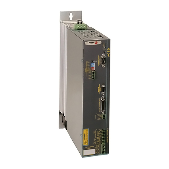
Page 25: Compact Servo Drive, Acsd
COMPACT SERVO DRIVE, ACSD Introduction ACSD is a compact speed servo drive family for controlling synchronous AC brushless servomotors. It has two series depending on the supply voltage they can be connected to: Hence, we will refer to: ACSD (H series) if the power supply voltage is 400 V AC ACSD (L series) if the power supply voltage is 220 V AC... -
Page 26: Dimensions
Dimensions 67 mm (2.63") 245 mm (9.64") ACSD 6 mm (0.23") 11 mm (0.43") F. 14 ACSD drives. Dimensions. Technical data · 220 V · L series · 400 V · H series Rated output current (A) Peak current (0.5 s) (A) 3 AC 220/240 V ±... -
Page 27: Connectors
Connectors Power terminals POWER INPUTS L1, L2, L3. Mains input terminals. POWER OUTPUTS U, V, W. Output terminals for the voltage applied to the motor. Current control with PWM on a carrier fre- quency of 8 kHz. When connecting to the motor, watch the matching of phases U-U, V-V and W-W. -
Page 28: Indicators
DRIVE OK. Drive Ok. (pins 6 and 7 of X2). Relay contact that closes when the internal status of the drive control is OK. It must be included in the electrical maneuver. PROG. DIGIT. INPUT Programmable digital input, (pins 8 and 9 of X2). Programmable digital input. -
Page 29: Push-Buttons And Switches
CROWBAR (ON). Indicator light on top of the RESET button. When lit, it indicates that the voltage of the internal bus has exceeded the preset voltage values and the ballast resistor has been activated. VBUS OK. Indicator light on top of the RESET button. When lit, it indicates that there is power voltage. -
Page 30: Front Panel And Pinout Of The Connectors
Front panel and pinout of the connectors B. Connector X1 -12V ±12 V RESET Power Supply +12V +5 V ACTIVITY NODE SELECT C. Connector X2 SPEED SELECT TERM INAL RESISTOR GNDa PROG. DIG. CANL SHIELD OUTPUT CANH SHIELD SPEED ENABLES DRIVE COMMON DRIVE OK... - Page 31 E. Input connector for motor fee Signal Function back and temperature sensor. A + signal B + signal Z + signal Phase switching U - Phase switching W - Phase switching V - N.C. Not connected N.C. N.C. A - signal B - signal Z - signal Phase switching U +...
-
Page 32: Unit Identification
Unit identification The specifications and version labels that come with each FAGOR ACSD digital drive show the following information: F. 16 A. Version label. B. Characteristics label. SOF, SOFP, MOT, CAN, CTR, POT and VAR indicate manufacturing related aspects (hardware design versions) that are useful for technical consultations and repairs. -
Page 33: Installation
INSTALLATION General considerations At the motor Remove the anti-corrosion paint of the shaft before mounting them on to the machine. The motor may be mounted as IM B5, IM V1 and IM V3. Watch for the ambient conditions mentioned in the section on general characteristics and also: ... -
Page 34: Electrical Connections
>50mm >30mm >10mm >50mm F. 18 Installation of ACSD modules. About the connection All the cables must be shielded, to reduce the interference on the control of the motor due to the commutation of the PWM. The shield of the motor power cable must be connected to the chassis screw at the bottom of the module and it, in turn, to mains ground. - Page 35 THREE PHASE Warning. Never make this connection because there is a risk of destroying the module. Autotransformer or Autotransformer or three -phase transformer three -phase transformer 3x2.5 mm² 3x2.5 mm² 220 or 380 V AC 220 or 380 V AC 380 V AC 380 V AC fuses...
- Page 36 NOTE. A thermal switch may optionally replace the fuses. NOTE. The secondary windings must have a star connection with its middle point con- nected to ground. Types of mains Depending on the diagram of the electric energy distribution circuit, there are three types of mains: TN, TT and IT.
- Page 37 TT diagram Distribution diagram that has a point directly connected to ground and the conduc- tive parts of the installation are connected to this ground point independently from the ground electrode of the power supply system. FACTORY LINE FACTORY LINE TRANSFORMER TRANSFORMER DIFFERENTIAL...
- Page 38 Use KV41 to indicate to the drive that an external ballast resistor has been connected. ACSD Drive ACSD Drive Internal External Ballast Ballast 2.5 mm F. 24 Ballast resistor connection diagram. Power connection. Drive - motor FAGOR cables MPC- 4x1.5+(2x1) , MPC- 4x1.5 MOTOR MPC- 4x2.5+(2x1) , MPC- 4x2.5 Holding brake OUTPUT (option)
- Page 39 MPC-4x1.5+(2x1) MPC-4x2.5 MPC-4x2.5+(2x1) NOTE. The length of the MPC cable must be specifically ordered (in meters). Codes of the sales reference of FAGOR power cables. MOTOR POWER CABLE Ex. MPC 4 x 0.5 M otor P ower C able On motors without brake...
-
Page 40: Cables
E3. SinCos taper shaft encoder 1024 ppt A1. SinCos multi-turn encoder 1024 ppt A3. SinCos multi-turn encoder 1024 ppt Cables FAGOR provides these full connections (cables + connectors): IECD, EEC-SP and CAN (without connectors). TTL encoder connecting cable, IECD The IECD cable transfers the motor feedback signals from the incremental TTL encoder (ref.I0) to the drive. -
Page 41: Can Field Bus Connection
Ready made cable EEC-SP-3/5/6/7/8/9/10/11/12/15/20/25/30/35/40/45/50/60 I TYPE Length in meters; connectors included Cable 3x2x0.14+4x0.14+2x0.5 Signal Pin (HD, Sub-D, Green M26) Yellow REFCOS Blue Front view E0C-12 Purple REFSIN Front view Black +485 Brown -485 Black (0.5 mm (0.5 mm +8 V White TEMP - Grey... -
Page 42: Codes Of The Fagor Cables
This cable ist supplied without connectors. Signal Signal Pin Brown White F. 32 Connection diagram of the cable for the CAN communication bus. Codes of the FAGOR cables Example: IECD- ENCODER-DRIVE CABLE CABLE OF INCREMENTAL ENCODER LENGTH (m) 05, 07, 10, 15, 20, 25, 30... -
Page 43: Connecting A Drive To A Pc. Rs-232 Serial Line
Example: EEC-SP- 20 ENCODER-DRIVE CABLE CABLE FOR SINUSOIDAL ENCODER LENGTH (m) 03, 05, 06, 07, 08, 09, 10, 11, 12, 15, 20, 25, 30, 35, 40, 45, 50, 60 SUB-D EOC-12 HD M26 F. 34 Sales reference of the EEC-SP cable. Example: CAN CABLE CAN CABLE CAN CABLE... -
Page 44: Diagram Of The Electrical Cabinet
Diagram of the electrical cabinet This is an orientative diagram for the installation of the electrical cabinet. This diagram may be modified according to the requirements of each application. It includes a simple circuit for the voltage supply of the brake of the servo motors. NOTE. -
Page 45: Initialization And Adjustment
Initialization and adjustment The system can only be initialized and adjusted using the CAN field bus (communication interface included in the ACSD drive). This process is carried out from the master device (CNC). NOTE. Remember that the serial line can only be used to down- load the software to the drive. - Page 46 SPEED SELECT Selector that can help the NODE SELECT select the node number and can confirm the communication speed of the CAN bus. How to select the bus speed? Proceed as follows to select the bus speed: Start the drive up (or do a reset) with the rotary switch in the “0” position.
- Page 47 Examples. To assign node number 13 to a drive, the SS selector must be in the OFF position and the rotary selector NS in the D position (13 in decimal), which results from the previous formula the node value: Node = 13+(16x0) = 13 To assign node number 20 to a drive, the SS switch must be in the ON position and the rotary selector NS in the 4 position, which results from the formula the node value:...
- Page 48 BUS ACTIVITY. This LED is the only element that, without a mas- ter CAN device, allows displaying the status of the unit. This indi- cator light informs of the status of the CAN bus and the status of the drive. The following table shows the different situations of the indicator light and their meanings.
-
Page 49: Parameters, Variables & Commands
PARAMETERS, VARIABLES & COMMANDS The parameters, variables and commands of the drive that are shown next may be used with any device that works as master. Besides all these, there are others that may be used to communicate the drive with the CNC. Notation <Group>... - Page 50 Note that all the parameters have the (RW), i.e. they can be read and written. Example of a modifiable variable: DV32 Fagor, RW: D Group, (V) Variable, (Nr) 32, (Fagor) Access level, (RW) modifiable. Parameter that cannot be modified with torque. Any parameter that for any reason cannot be modified while the unit has torque will have an asterisk (*) identifying it as such next to its access level.
-
Page 51: Groups
Groups B. Non-programmable inputs and outputs BV14 FAGOR, RO S32972 NotProgrammableIOs Function Indicates the logic values of the electrical signals of the drive's control. 24 V at the electrical input mean a logic 1 at the bits of this variable. - Page 52 CP30 FAGOR, RW S33076 CurrentCommandFilter1Type Function Parameter in charge of disabling/enabling the current filter. Valid values 0/1 Disable/Enable. Default value Disable. CP31 FAGOR, RW S33080 CurrentCommandFilter1Frequency Function Sets the natural frequency in Hz of a notch filter that acts upon the current command.
- Page 53 - 50.00 ... 50.00 Arms (rms value). CV10 Current CV11 reading _sin _cos CV10 FAGOR, RO S33073 Current1Offset Function Value of the automatic compensation of the current feed- back offset of phase V. Valid values - 2.000 ... 2.000 A (depends on the drive connected).
- Page 54 4 ... 1 Reserved DriveStatusWordToggleBit Version Modified in version 02.04. Bit 10 has been added. DV32 FAGOR, RW S00134 MasterControlWord Function This variable contains a numerical data coded into 16 binary bits and represents the control signals that act upon the drive through the serial line.
- Page 55 Valid values 1 ... 9999 ms, 0 (infinite). Default value 50 ms. AutomaticInitialization GP15 FAGOR, RW S33494 Function When having a SinCos or SinCoder encoder it enables reading MP1 directly from the sensor and consequently loading certain drive parameter automatically.
- Page 56 0 and 1 (with 1, it resets the unit). GV16 BASIC, RO S33484 MotorTableVersion Function Version of the motor table. GV75 FAGOR, RO S00375 ErrorList Function List of the error numbers active in the unit. Valid values - 32 768 ... 32 767.
- Page 57 • Execute GC3. The motor will start positioning and it will be completed after about 30 or 40 seconds. At this instant, the new Rho has been calculated. Its value may be displayed in the RV3 variable. • Select MP1 and edit the motor type. •...
- Page 58 K. Monitoring USER, RW S33882 ExtBallastPower Function Contains the value of power of the external ballast resistor. Valid values 200 ... 2 000 W. Default value 200 W. USER, RW S33884 ExtBallastEnergyPulse Function Contains the value of the energy pulse that can be dissipated by the external ballast resistor.
- Page 59 Contains the motor rated current. Manipulating MP3 may affect parameter CP20 directly. See parameter CP20. Valid values 0.00 ... 50.00 Arms. Depends on the motor connected. Default value 10.00 Arms. MP24 *FAGOR, RW S33988 MotorMomentumOfInertia Function Motor inertia. Valid values 0.1 ...
- Page 60 Valid values 0.00 ... 1 000.00 %. Default value 0.00 %. NP116 FAGOR, RO S00116 ResolutionOfFeedback1 Function Parameter that cannot be modified by the user that “tells” the CNC the number of pulses of the motor feedback.
- Page 61 0 and 1. X2.1 OV10 PROG_DIGIT_OUTPUT X2.2 P. Position loop PP217 FAGOR, RW S00348 AccelerationFeedForwardPercentage Function It sets the how much acceleration feed-forward is applied in position control and in velocity control. It is similar to parameter ACFGAIN <P26> of the axes of the 8055/55i CNC.
- Page 62 FAGOR CNC. ACTIVATE the control with FAGOR CNCs QP17= 0 QP17= 1 DEACTIVATE the control with FAGOR CNCs Bit Nr Meaning 15...7 Reserved...
- Page 63 Default value With FAGOR CNC as Set all the bits to 0. master device With another master It is recommended to set all the device bits to 1, except bit 5 to 0. QV22 FAGOR, RO S00022 IDNListOfInvalidOperationDataForCP3 Function Variable containing the parameters that are readjusted by the drive when it issues an “error E.502: incompatible...
- Page 64 FAGOR, RW S34270 FeedbackSineOffset FAGOR, RW S34271 FeedbackCosineOffset Function Compensation (offset mode) of the sine/cosine signal that goes from the motor feedback to the drive. Valid values - 2 000 ... 2 000. Default value RP20 USER, RW S34305 StegmanABLevelSense Function Motor feedback failure protection sensitivity adjustment.
- Page 65 SP2: 0.1... 999.9 ms. Default value Depends on the motor-drive combination. SP10 BASIC, RW S00091 VelocityLimit Function Maximum velocity limit for SV7 (VelocityCommandFinal). Valid values 0 ... 110 % of the motor rated speed in rpm. Default value 1 000 rpm. SP42 USER, RW S00124...
- Page 66 SP50 BASIC, RW S34782 VelocityFeedbackFilterFrequency Function Cutoff frequency of the first-order low-pass filter after the velocity feedback. Valid values 0 (the filter is not applied) ... 4 000 Hz. Default value 800 Hz. Low-pass filter SP50>0 1Vpp fc=SP50 encoder SP50=0 SP60 BASIC, RW S00138...
- Page 67 If anytime during the sequence, the Drive Enable is interrupted, the motor will turn by inertia. SP65=0 cancels this limiting effect. Power Off Power Off Motor free Motor Motor Speed Speed Drive Drive Enable Enable Speed Speed Enable Enable Valid values 0.0 (by default), ..., 400.0 rpm/ms.
- Page 68 T. Torque and power TP10 USER, RW S34670 ConstantPositiveTorqueCompensation Function Constant friction compensation in the positive direction of the velocity. It is a constant value for all the positive reference speeds. See the figures later on. Valid values 0.0 (by default), ..., 100.0 N·m. ConstantNegativeTorqueCompensation TP11 USER, RW...
- Page 69 TP14 USER, RW S34676 TorqueCompensationTimeConstant Function Time constant of the torque compensation. Before applying it, it is filtered with a low-pass filter to improve the friction behavior in velocity direction changes. The constant friction suddenly changes when changing the sign of the reference speed. The filters “smoothes” the compensation torque preventing jerks in the system when reversing the moving direction and better modeling the behavior of friction.
- Page 70 TP15 USER, RW S34677 TorqueCompensationSpeedHysteresis Function Amplitude of the hysteresis in friction torque compensation. NOTE. With TP15=0, the drive internally sets a fixed Hysteresis amplitude of about SP10 rpm /10 000 to compensate the friction torque. Remember that SP10 is the maximum speed of the application;...
-
Page 71: Error Codes
ERROR CODES E.001 Internal Contact Fagor Automation. E.003 With torque, there is a drop at the power bus Probably one of the three-phase lines has dropped or a drive has failed. Verify that the lines and the drives are in good condition and restart the system. - Page 72 IF t1<GP3 THE AFTER GP9 MOTOR TORQUE ON=0; ELSE [MOTOR TORQUE ON=0 AND E.004] SP42 Time E.106 Extreme temperature at the heatsink (of the IGBT's) The drive is carrying out a task that overheats the power devices. Stop the system for several minutes and decrease the effort demanded from the drive.
- Page 73 The parameters may be wrong or there is a fault at the drive. Contact Fagor Automation. After displaying E.214, one of the codes of the following table will be displayed. The drive where the alarm has been detected is:...
- Page 74 The error will disappear when the parameters (readjusted in RAM memory by the drive) are saved into E²PROM memory using the GC1 command. E.506 Motor table missing Contact Fagor Automation. ACSD-74/80 Digital Brushless AC Servo Drive system - Ref.1609...
- Page 75 Some of the sine or cosine signals of the encoder has reached a peak level lower than 150 mV. + 0.15 V - 0.15 V Contact Fagor Automation. E.801 Encoder not detected The drive has not detected the rotor sensor.
-
Page 76: Parameters, Variables & Commands. Ids
PARAMETERS, VARIABLES & COMMANDS. ID Mnem. Name Level IDSER Ac Min. Max. Def. Units Pag. BV14 NotProgrammableIOs Fagor 32972 65535 CurrentProportionalGain Fagor 00106 RW 0 CurrentIntegralTime Fagor 00107 RW 0 CP20 CurrentLimit Basic 33075 RW 0.00 50.00 0.00 CP30 CurrentCommandFilter1Type... - Page 77 Mnem. Name Level IDSER Ac Min. Max. Def. Units Pag. NP123 FeedConstant Fagor 00123 RW 0 50000 DigitalOutputPolarity User 34184 RW 0 OV10 DigitalOutputs User 34178 PC146 NCControlledHoming Fagor 00146 RW 0 PP217 AccelerationFeedforwardPercentage Fagor 00348 RW 0.0 120.0 PV51...
- Page 78 User notes ACSD-78/80 Digital Brushless AC Servo Drive system - Ref.1609...
- Page 79 User notes Digital Brushless AC Servo Drive system - Ref.1609 ACSD-79/80...
- Page 80 Fagor Automation S. Coop. B.º San Andrés, 19 - Apdo. 144 E-20500 Arrasate-Mondragón, Gipuzkoa ·Spain· Tel: +34 943 719 200 +34 943 039 800 Fax: +34 943 791 712 E-mail: info@fagorautomation.es www.fagorautomation.com ACSD-80/80 Digital Brushless AC Servo Drive system - Ref.1609...
- Page 81 Encoder not initialized E.803 fc=SP50 SP50=0 MOTOR PARAMETERS Motor type TTL ENCODER MOTOR SERIES Torque constant FAGOR SYNCHRONOUS MOTOR 1VPP ENCODER SIZE 2, 4, 6 Rated current SIZE 1, 3, 5, 7 LENGTH 1, 2, 3, 4, 6 MP24 Inertia...
- Page 82 ERROR FUNCTIONS Function "E.003" Power Supply fault Function "E.106" Function "E.200" Overspeed Drive Overtemp speed 1, 2 or 3 lines lost 1 line lost Power Supply 1.12 x rated motor speed 105 ºC Rated motor speed Drive Enable "E.106" Speed Enable "E.200"...