Advertisement
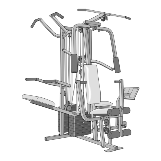
Class HC Fitness Product
Model No. WEEVSY62000
Serial No.
Write the serial number in the
space above for reference.
Serial Number Decal (Under Seat)
QUESTIONS?
As a manufacturer, we are com-
mitted to providing complete
customer satisfaction. If you
have questions, or if there are
missing or damaged parts, we
will guarantee complete satisfac-
tion through our Customer
Service Department.
Please CALL:
0345-089009
Or WRITE:
ICON Health & Fitness Ltd.
Unit 4
Revie Road Industrial Estate
Revie Road
Leeds
LS11 8JG
CAUTION
Read all precautions and instruc-
tions in this manual before using
this equipment. Save this manual
for future reference.
USER'S MANUAL
Visit our website at
www.weiderfitness.com
TM
Advertisement
Table of Contents

Related Manuals for Weider WEEVSY62000


Summary of Contents for Weider WEEVSY62000
- Page 1 Class HC Fitness Product Model No. WEEVSY62000 USER'S MANUAL Serial No. Write the serial number in the space above for reference. Serial Number Decal (Under Seat) QUESTIONS? As a manufacturer, we are com- mitted to providing complete customer satisfaction. If you...
- Page 2 Note: A PART IDENTIFICATION CHART and a PART LIST/EXPLODED DRAWING are attached in the centre of this manual. Remove the PART IDENTIFICATION CHART and the PART LIST/EXPLODED DRAWING before beginning assembly. WEIDER is a registered trademark of ICON Health & Fitness, Inc.
-
Page 3: Important Precautions
IMPORTANT PRECAUTIONS WARNING: To reduce the risk of serious injury, read the following important precautions before using the home gym system. 1. It is the responsibility of the owner to ensure arms before kneeling on the assist arm. The that all users of the home gym system are assist arm can drop quickly when your body adequately informed of all precautions. -
Page 4: Before You Begin
Whether your goal is ing. The model number is WEEVSY62000. The serial to tone your body, build dramatic muscle size and number can be found on a decal attached to the strength, or improve your cardiovascular system, the home gym system (see the front cover of this manual). -
Page 5: Assembly
ASSEMBLY Before beginning assembly, carefully read the • As you assemble the home gym system be sure following information and instructions: that all parts are oriented as shown in the drawings. • Place all parts of the home gym system in a cleared area and remove the packing materials;... - Page 6 2. Slide the Assist Upright (74) and the Leg Press Upright (56) onto the indicated 5/16” x 2 1/2” Carriage Bolts (1) in the Stabiliser (5). The high side of the brackets on the Assist Upright and Leg Press Upright should be on the side shown.
-
Page 7: On The Base (4) As Shown. Set Two Weight
4. Press a 2” Square Inner Cap (27) into the end of the Top Frame (55). Press a 1 3/4” Square Inner Cap (44) into each end of the crossbar on the Top Frame. Press two Round Inner Caps (111) into the top of the crossbar. Attach the Top Frame (55) to the Assist Upright (74) and the Leg Press Upright (56) Crossbar... - Page 8 7. Press a Weight Tube Bumper (64) into the end of the Short Weight Tube (108). Insert the Holes Weight Tube into the front stack of Weights (25). Be sure that the pin on the Weight Tube is sitting in the pin grooves in the top Weight.
- Page 9 9. Attach the upper ends of the Short Weight Guides (73) to the Top Frame (55) with a 5/16” x 6” Bolt (60), two 1/2” x 3/4” Spacers (61), and a 5/16” Nylon Locknut (3). Attach the upper ends of the Long Weight Guides (62) to the Top Frame (55) in the same manner.
- Page 10 12. Press a 1” Round Inner Cap (49) into one of the Press Arms (46). Press a 1 3/4” Square Inner Cap (44) into the Press Arm. Attach the Press Arm (46) to one side of the Press Frame (17) with two 5/16” x 2 1/2” Bolts (22) and two 5/16”...
- Page 11 15. See the inset drawing. Attach the Military Press Arm (84) to the Pivot Arm (101) with two 5/16” x 2 1/4” Bolts (33) and two 5/16” Nylon Locknuts (3). Press two 1 1/2” Square Inner Caps (32) into the Military Press Arm (84). Press two 1” Round Inner Caps (49) into the Military Press Arm.
-
Page 12: Cable Diagrams
17. Attach the Left Pull-up Arm (75) and the Right Pull-up Arm (77) to the Assist Upright (74) with two 5/16” x 2 3/4” Bolts (11) and two 5/16” Nylon Locknuts (3). Attach the Left Dip Arm (78) and the Right Dip Arm (79) to the Assist Upright (74) with two 5/16”... - Page 13 20. Wrap the High Cable (58) around a “V”-Pulley (50). Attach the “V”-Pulley and a Long Cable Trap (31) to the indicated bracket on the Front Upright (42) with a 3/8” x 2 1/2” Bolt (86) and a 3/8” Nylon Locknut (21). Be sure that the Long Cable Trap is positioned to hold the Cable in place.
-
Page 14: Do Not Tighten The Nylon Locknuts Yet
24. See the inset drawing. Wrap the High Cable (58) around a 3 1/2” Pulley (15). Attach the Pulley and a set of Pulley Covers (114) to the Small tabs upper hole in a Long “U”-Bracket (57) with a should be up. 3/8”... - Page 15 27. Locate the Low Cable (23). Route the Low Cable under the 3 1/2” Low Pulley (102). Be sure that the end of the Cable with the ball is on the indicated side of the Press Frame (17) and that the Cable is between the Pulley and the crossbar on the Press Frame.
-
Page 16: Bracket
31. Attach the end of the Low Cable (23) to the Long “U”-Bracket (57) with a 1/4” Nylon Locknut (2) and a 1/4” Flat Washer (10). Do not completely tighten the Nylon Locknut. It should be threaded onto the end of the Cable so only a couple of threads are showing above the Nylon Locknut, as shown in the inset drawing. - Page 17 34. Wrap the Military Press Cable (72) around a “V”-Pulley (50). Attach the “V”-Pulley to the Top Frame (55) with a 3/8” x 2 1/2” Bolt (86) and a 3/8” Nylon Locknut (21). Wrap the Military Press Cable (72) around a 3 1/2”...
- Page 18 36. Slide a 5/16” Flat Washer (8) onto a 5/16” x 2 3/4” Bolt (11). Insert the Bolt through the indi- cated hole in the Pivot Arm (101). The Bolt must be inserted from the side shown. Slide another 5/16” Flat Washer (8) onto the Bolt.
- Page 19 38. Locate the Leg Press Cable (99). Attach the end of the Leg Press Cable to the Long “U”- Bracket (57) with a 1/4” Nylon Locknut (2) and a 1/4” Flat Washer (10). Do not completely tighten the Nylon Locknut. It should be threaded onto the end of the Cable only a couple of turns, as shown in the inset drawing.
- Page 20 40. Locate and open the parts bag labelled “SEAT ASSEMBLY.” Insert a 1/4” x 2 1/2” Carriage Bolt (92) through the centre hole in a Seat Plate (37). Attach the Seat Plate to the Rear Backrest (85) with two 1/4” x 3/4” Screws (18). Insert the 1/4”...
- Page 21 43. Attach the Front Backrest (41) to the Front Upright (42) with two 1/4” x 2 1/2” Screws (43) and two 1/4” Flat Washers (10). The Backrest must be oriented as shown. Thick 44. Press a 1 1/2” Square Inner Cap (32) into the Front Seat Frame (36).
- Page 22 47. Press two 3/4” Round Inner Caps (34) into each Pad Tube (28). Insert a Pad Tube (28) into the Front Seat Frame (36). Slide a Foam Pad (30) onto each end of the Pad Tube. Insert the other Pad Tube (28) into the Leg Lever (29).
-
Page 23: How To Use The Home Gym System
HOW TO USE THE HOME GYM SYSTEM The instructions below describe how each part of the home gym system can be adjusted. IMPORTANT: When attaching the lat bar or nylon strap, make sure that the attachments are in the cor- rect starting position for the exercise to be performed. - Page 24 ATTACHING AND REMOVING THE SEAT To attach the Seat (13), set the bracket on the Front Seat Frame (36) onto the indicated pins on the Front Upright (42). Attach the Front Seat Frame to the Front Upright with the 5/16” x 2 3/4” Carriage Bolt (14) and the Seat Knob (40).
-
Page 25: Weight Resistance Chart
WEIGHT RESISTANCE CHART This chart shows the approximate weight resistance at each weight station. “Top” refers to the 6,5-pound top weight. The other numbers refer to the 12,5-pound weight plates. The butterfly arm resistance listed is the resis- tance for each butterfly arm. Note: The actual resistance at each weight station may vary due to differ- ences in individual weight plates, as well as friction between the cables, pulleys, and weight guides. - Page 26 TROUBLE-SHOOTING AND MAINTENANCE Inspect and tighten all parts each time you use the home gym system. Replace any worn parts immediately. The home gym system can be cleaned using a damp cloth and mild non-abrasive detergent. Do not use solvents. TIGHTENING THE CABLES Woven cable, the type of cable used on the home gym system, can stretch slightly when it is first used.
- Page 27 CABLE DIAGRAMS The cable diagrams on this page show the proper routing of the High Cable (58), the Low Cable (23), the Military Press Cable (72), and the Leg Press Cable (99). Use the diagrams to be sure that the four cables and the cable traps have been assembled correctly.
-
Page 28: Ordering Replacement Parts
Tel: Country Code: 0345-089009 Fax: 0113-2411120 To help us assist you, please be prepared to give the following information: 1. The MODEL NUMBER of the product (WEEVSY62000) 2. The NAME of the product (WEIDER ® PRO 9645 home gym system) 3. - Page 29 Note: Assembly is divided into four stages: 1) frame assembly, 2) arm assembly, 3) cable and pulley assembly, and 4) seat and backrest assembly. The hardware for each stage is packaged separately. WAIT UNTIL YOU BEGIN EACH ASSEMBLY STAGE TO OPEN THE PARTS BAG LABELLED FOR THAT ASSEMBLY STAGE. WEEVSY62000 R0301A...
- Page 30 2" Square Inner Cap (27) 2" Square Outer Cap (51) 1 1/2" Square Inner Cap (32) 1 3/4" Square Inner Cap (44) 1" x 2" Inner Cap (107) 1" Round Inner Cap (49) Round Inner Cap (111) 1 1/4" Round Inner Cap (109) 3/4"...
- Page 32 REMOVE THIS PART LIST/EXPLODED DRAWING CHART FROM THE MANUAL...
- Page 33 PART LIST—Model No. WEEVSY62000 R0301A Key Qty. Description Key Qty. Description Key Qty. Description 5/16” x 2 1/2” Carriage Front Backrest Handle Bolt Front Upright 5” Plastic Handgrip 1/4” Nylon Locknut 1/4” x 2 1/2” Screw Military Press Arm 5/16” Nylon Locknut 1 3/4”...
- Page 34 EXPLODED DRAWING—Model No. WEEVSY62000 R0301A...