YASKAWA F7 User Manual
Hide thumbs
Also See for F7:
- Instruction manual (463 pages) ,
- Programming manual (202 pages) ,
- Connection manual (64 pages)

Related Manuals for YASKAWA F7


Summary of Contents for YASKAWA F7
- Page 1 Aotewell Email: Sales@aotewell.com F7 Drive User Manual Model: CIMR-F7U Document Number: TM.F7.01 Tel: +(86) 755 8660 6182 Aotewell http://www.aotewell.com...
- Page 2 YASKAWA must be supplied to the end user with appropriate warnings and instructions as to that part’s safe use and operation. Any warnings provided by YASKAWA must be promptly provided to the end user. YASKAWA offers an express warranty only as to the quality of its products in conforming to standards and specifications published in the YASKAWA manual.
- Page 3 To avoid unnecessary fault displays caused by contactors or output switches placed between Drive and motor, auxiliary contacts must be properly integrated into the control logic circuit. YASKAWA is not responsible for any modification of the product made by the user; doing so will void the warranty. This •...
- Page 4 Version 3020. The F7 Drive is a Pulse Width Modulated Drive for AC 3-Phase induction motors. This type of Drive is also known as an Adjustable Frequency Drive, Variable Frequency Drive, AC Drive, AFD, ASD, VFD, VSD, and Inverter. In this manual, the F7 Drive will be referred to as the “Drive”.
- Page 5 http://www.aotewell.com Aotewell Email: Sales@aotewell.com Drive Output Specifications The standard Drive specifications are listed in the following tables. 208-240Vac Table i.2 208-240Vac Drive Specifications 208-240Vac 208-230Vac Model Number CIMR-F7U 20P4 20P7 21P5 22P2 23P7 25P5 27P5 2011 2015 2018 2022 2030 2037 2045 2055 2075 2090 2110...
- Page 6 http://www.aotewell.com Aotewell Email: Sales@aotewell.com 480Vac Table i.3 480Vac Drive Specifications Model Number CIMR-F7U 40P4 40P7 41P5 42P2 43P7 44P0 45P5 47P5 4011 4015 4018 4022 Rated output 13.0 18.0 24.0 30.0 34.0 capacity (kVA) 0.5/0.75 1.5/2 Horsepower Rated output current (A) 12.5 17.0 24.0...
- Page 7 http://www.aotewell.com Aotewell Email: Sales@aotewell.com Notes: Tel: +(86) 755 8660 6182 Aotewell http://www.aotewell.com...
-
Page 8: Table Of Contents
Warnings and Cautions..................i Introduction ..................... iii Table of Contents................... vii Chapter 1 - Physical Installation ................1-1 F7 Model Number, Enclosure, Heat Loss, and Weight.........1-2 Confirmations upon Delivery.................1-3 Component Names ..................1-5 Exterior and Mounting Dimensions ...............1-7 Checking and Controlling the Installation Site ..........1-11 Installation Orientation and Clearances ............1-12... -
Page 9: Table Of Contents
http://www.aotewell.com Aotewell Email: Sales@aotewell.com Chapter 4 - Start-Up ....................4-1 Drive Start-Up Preparation ................4-2 Drive Start-Up Procedures ................4-5 Chapter 5 - Basic Programming ................5-1 Description of Parameter Tables ..............5-2 Control Method ..................... 5-2 Speed Command Source ................5-3 Run Command Source ................. -
Page 10: Table Of Contents
Removing and Mounting the Terminal Card ..........7-7 Appendix A - Parameters..................A-1 F7 Parameter List ..................A-3 F7 Monitor List ................... A-38 F7 Fault Trace List ..................A-41 F7 Fault History List ................... A-41 Appendix B - Capacity Related Parameters............B-1 Drive Capacity Selection................B-2 Parameters Affected by Drive Capacity Setting........... - Page 11 Branch Circuit Short Circuit Protection ............E-2 Branch Circuit Overload Protection ............. E-5 Peripheral Devices ..................E-6 Appendix F - Spare Parts ..................F-1 F7 Primary Spare Parts - 208/230/240Vac...........F-2 F7 Primary Spare Parts - 480Vac..............F-3 Index ...................... Index-1 Support Services ..............Inside rear cover...
-
Page 12: Table Of Contents
Aotewell Email: Sales@aotewell.com Chapter 1 Physical Installation This chapter describes the requirements for receiving and installing the F7 Drive. F7 Model Number, Enclosure, Heat Loss, and Weight ..1-2 Confirmations upon Delivery ..........1-3 Component Names ............1-5 Exterior and Mounting Dimensions ........1-7 Checking and Controlling the Installation Site.... -
Page 13: F7 Model Number, Enclosure, Heat Loss, And Weight
Aotewell Email: Sales@aotewell.com F7 Model Number, Enclosure, Heat Loss, and Weight Table 1.1 F7 Model Number and Enclosure Style Input Heat Loss (watts) Weight Voltage Enclosure Style Model-Number lb (kg) Heatsink Internal Total 3-Phase CIMR-F7U20P4 NEMA Type 1 (IP20) -
Page 14: Confirmations Upon Delivery
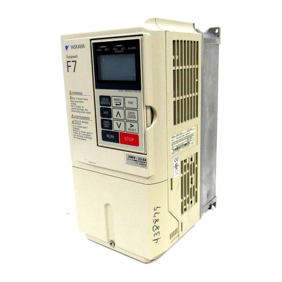
Use a screwdriver or other tool to check for tightness. If there are any irregularities in the above items, contact the shipping company, or the distributor / representative who sold the Drive, or a Yaskawa office immediately. Nameplate Information A nameplate is attached to the right side of each Drive. The following nameplate is an example for a standard Drive. - Page 15 Aotewell Email: Sales@aotewell.com Drive Model Numbers The model number on the nameplate indicates the design specification, voltage, and rating of the Drive in alphanumeric codes. CIMR – F7 U 2 0 2 2 AC Drive F7 Family Spec Rating...
-
Page 16: Component Names
http://www.aotewell.com Aotewell Email: Sales@aotewell.com Component Names Models CIMR-F7U20P4 thru 2018 and 40P4 thru 4018 The external appearance, component names, and terminal arrangement of the Drive are shown in Fig 1.4 and 1.5. Top protective cover [Required for NEMA Type 1 (IEC IP20)] Mounting hole Front cover Digital Operator... - Page 17 http://www.aotewell.com Aotewell Email: Sales@aotewell.com Models CIMR-F7U2022 thru 2110 and 4030 thru 4300 The external appearance, component names, and terminal arrangement of the Drive are shown in Fig 1.6 and 1.7. Mounting holes Mounting holes Drive cover Drive cover Cooling fan Cooling fan Front cover Front cover...
-
Page 18: Exterior And Mounting Dimensions
Aotewell Email: Sales@aotewell.com Exterior and Mounting Dimensions DIMENSIONS: F7 (NEMA 1) 208-240V (F7U20P4-2018) 480V (F7U40P4-4018) Physical Installation 1 - 7 Tel: +(86) 755 8660 6182 Aotewell http://www.aotewell.com... - Page 19 http://www.aotewell.com Aotewell Email: Sales@aotewell.com Physical Installation 1 - 8 Tel: +(86) 755 8660 6182 Aotewell http://www.aotewell.com...
- Page 20 http://www.aotewell.com Aotewell Email: Sales@aotewell.com Physical Installation 1 - 9 Tel: +(86) 755 8660 6182 Aotewell http://www.aotewell.com...
- Page 21 http://www.aotewell.com Aotewell Email: Sales@aotewell.com Physical Installation 1 - 10 Tel: +(86) 755 8660 6182 Aotewell http://www.aotewell.com...
-
Page 22: Checking And Controlling The Installation Site
http://www.aotewell.com Aotewell Email: Sales@aotewell.com Checking and Controlling the Installation Site Install the Drive as described below and maintain optimum conditions. Installation Site Install the Drive to a non-combustible surface under the following conditions in UL Pollution Degree 2 environments. This excludes wet locations where pollution may become conductive due to moisture, and locations containing conductive foreign matter. -
Page 23: Installation Orientation And Clearances
http://www.aotewell.com Aotewell Email: Sales@aotewell.com Installation Orientation and Clearances Install the Drive vertically so as not to reduce the cooling efficiency. When installing the Drive, always provide the following installation clearances to allow normal heat dissipation and air flow. Ensure that the heatsink is against a closed surface to avoid diverting cooling air around the heatsink. -
Page 24: Removing And Attaching The Terminal Cover
http://www.aotewell.com Aotewell Email: Sales@aotewell.com Removing and Attaching the Terminal Cover Remove the terminal cover to connect cables to the control circuit and main circuit terminals. Removing the Terminal Cover Models CIMR-F7U20P4 thru 2018 and 40P4 thru 4018 Loosen the screw at the bottom of the terminal cover, press in on the sides of the terminal cover in the directions of arrows 1, and then lift up on the terminal in the direction of arrow 2. -
Page 25: Removing/Attaching The Digital Operator And Front Cover
http://www.aotewell.com Aotewell Email: Sales@aotewell.com Removing/Attaching the Digital Operator and Front Cover Models CIMR-F7U20P4 thru 2018 and 40P4 thru 4018 For Models CIMR-F7U2018/4018 and smaller, remove the terminal cover and then use the following procedures to remove the Digital Operator and front cover. Removing the Digital Operator Press on the side of the Digital Operator in the direction of arrow 1 to unlock, then lift the Digital Operator in the direction of arrow 2 to remove it as shown in Fig 1.11. - Page 26 http://www.aotewell.com Aotewell Email: Sales@aotewell.com Mounting the Digital Operator After attaching the front cover, mount the Digital Operator onto the Drive using the following procedure: 1. Hook the Digital Operator at A (two locations) on the left side of the opening on the front cover by moving in the direction of arrow 1 as shown in the following illustration.
- Page 27 http://www.aotewell.com Aotewell Email: Sales@aotewell.com Models CIMR-F7U2022 thru 2110 and 4030 thru 4300 For Models CIMR-F7U2022/4030 and larger, remove the terminal cover and then use the following procedures to remove the Digital Operator and front cover. Removing the Digital Operator Use the same procedure for Models CIMR-F7U20P4 thru 2018 and 40P4 thru 4018. Removing the Front Cover Loosen all screws on the front cover.
-
Page 28: Chapter 2 - Electrical Installation
http://www.aotewell.com Aotewell Email: Sales@aotewell.com Chapter 2 Electrical Installation This chapter describes wiring terminals, main circuit terminal connections, main circuit terminal wiring specifications, control circuit terminals, and control circuit wiring specifications. Terminal Block Configuration ..........2-2 Wiring Main Circuit Terminals ........... 2-3 Control Wiring .............. -
Page 29: Terminal Block Configuration
http://www.aotewell.com Aotewell Email: Sales@aotewell.com Terminal Block Configuration The wiring terminals are shown in Fig 2.1, Fig 2.2 and Fig 2.3. Control circuit terminal layout label Control circuit terminals Ground terminal See Fig. 2.3 below for actual terminal layout Main circuit terminals Charge indicator Ground terminal Ground terminal... -
Page 30: Wiring Main Circuit Terminals
http://www.aotewell.com Aotewell Email: Sales@aotewell.com Wiring Main Circuit Terminals Applicable Wire Sizes and Closed-loop Connectors Select the appropriate wires and crimp terminals from Table 2.1 and Table 2.2. Refer to instruction manual TOE-C726-2 for Braking Resistor Unit and Braking Unit wire sizes. Table 2.1 208-240Vac Wire Sizes and Connector Specifications Possible Wire Recommended... - Page 31 http://www.aotewell.com Aotewell Email: Sales@aotewell.com Table 2.1 208-240Vac Wire Sizes and Connector Specifications (Continued) Possible Wire Recommended Clamping Sizes AWG Wire Size AWG Drive Model Terminal Torque Wire Terminal Symbol CIMR-F7U Screws lb. in. Type (N•m) 154.8 to 197.9 R/L1, S/L2, T/L3, 1 U/T1, (17.6 to 22.5) (100)
- Page 32 http://www.aotewell.com Aotewell Email: Sales@aotewell.com Table 2.2 480Vac Wire Sizes and Connector Specifications Possible Wire Recommended Clamping Sizes AWG Wire Size AWG Drive Model Terminal Torque Terminal Symbol Wire Type CIMR-F7U Screws lb. in. (N•m) R/L1, S/L2, T/L3, 2, B1, B2 10.6 to 13.2 14 to 10 U/T1, V/T2, W/T3...
- Page 33 http://www.aotewell.com Aotewell Email: Sales@aotewell.com Table 2.2 480Vac Wire Sizes and Connector Specifications (Continued) Possible Wire Recommended Clamping Sizes AWG Wire Size AWG Drive Model Terminal Torque Terminal Symbol Wire Type CIMR-F7U Screws lb. in. (N•m) R/L1, S/L2, T/L3, 3, R1/L11, S1/L21, (30) 35.2 to 43.99 T1/L31...
- Page 34 http://www.aotewell.com Aotewell Email: Sales@aotewell.com Table 2.2 480Vac Wire Sizes and Connector Specifications (Continued) Possible Wire Recommended Clamping Sizes AWG Wire Size AWG Drive Model Terminal Torque Terminal Symbol Wire Type CIMR-F7U Screws lb. in. (N•m) 3/0 × 2P R/L1, S/L2, T/L3, 1, R1/L11, S1/L21, T1/L33 (80 ×...
- Page 35 http://www.aotewell.com Aotewell Email: Sales@aotewell.com The use of UL listed closed-loop connectors or CSA certified ring connectors sized for the selected wire gauge is recommended to maintain proper clearances when wiring the Drive. Install connectors per manufacturer recom- mendation using the correct crimp tool. Table 2.3 lists a suitable closed-loop connector manufactured by JST Cor- poration.
- Page 36 *1 Input fuses or molded case circuit breakers are required for proper branch circuit protection for all Drives. Failure to use recommended fuses/circuit breakers (See Appendix E) may result in damage to the Drive and/or personal injury. *2 Consult your Yaskawa representative before using 12-pulse rectification circuit configuration. Electrical Installation 2 - 9...
- Page 37 *1 Input fuses or molded case circuit breakers are required for proper branch circuit protection for all Drives. Failure to use recommended fuses/circuit breakers (See Appendix E) may result in damage to the Drive and/or personal injury. *2 Consult your Yaskawa representative before using 12-pulse rectification circuit configuration. Electrical Installation 2 - 10...
- Page 38 Email: Sales@aotewell.com Cable Length between Drive and Motor The F7 should be installed as close as possible to the motor to minimize the length of the load side power cable needed between the Drive and motor. If the cable between the Drive and the motor is long, the high-frequency leakage current will increase, causing the Drive output current to increase as well.
- Page 39 http://www.aotewell.com Aotewell Email: Sales@aotewell.com Dynamic Braking Connections General Dynamic braking (DB) enables the motor to be brought to a smooth and rapid stop. This is achieved by dissipating the regenerative energy of the AC motor across the resistive components of the Dynamic Braking option. For further details on dynamic braking operation, see the instruction sheet shipped with dynamic braking components.
- Page 40 http://www.aotewell.com Aotewell Email: Sales@aotewell.com Heat Sink Mount Resistor Installation 1. Remove the Drive from its mounting for access to the rear of the heat sink. 2. Attach the Heat Sink Mount Resistor on the back of the Drive’s heat sink with screws M4 x 10mm (0.7mm pitch), as shown in figure below.
- Page 41 http://www.aotewell.com Aotewell Email: Sales@aotewell.com Remote Mount Resistor Unit Installation Using Internal Braking Transistor (for F7U20P4 thru F7U2018 and F7U40P4 thru F7U4018) Since the Remote Mount Resistor Unit generates heat during dynamic braking operation, install it in a location away from other equipment.
- Page 42 http://www.aotewell.com Aotewell Email: Sales@aotewell.com Braking Transistor Unit(s) and Remote Mount Resistor Unit(s) Installation (for F7U2022 thru F7U2110 and F7U4022 thru F7U4300) Since the Remote Mount Resistor Unit generates heat during dynamic braking operation, install it to a noncombustible surface in a location away from other equipment. Select mounting locations for Braking Transistor Unit(s) and Remote Mount Resistor Unit(s) so that wiring between the Drive and the Braking Transistor Unit is 16 feet (5m) or less, and the wiring between each Braking Transistor Unit and its associated Remote Mount Resistor Unit, is less than 33 feet (10m).
- Page 43 http://www.aotewell.com Aotewell Email: Sales@aotewell.com ‡ REMOTE MOUNT RESISTOR UNIT ‡ Applies when SC is jumpered to SP and S3 is programmed as External Fault. Fig 2.7 Wiring Single Braking Transistor Unit and Remote Mount Resistor Unit to Drive (F7U2022 thru F7U2110 and F7U4022 thru F7U4300) Electrical Installation 2 - 16 Tel: +(86) 755 8660 6182 Aotewell...
- Page 44 http://www.aotewell.com Aotewell Email: Sales@aotewell.com 6. If two or more Braking Transistor Units and Remote Mount Resistor Units are being installed, connect them to the Drive and to external circuitry according to Fig 2.8. ‡ R1 R2 R1 R2 R1 R2 R1 R2 ‡...
- Page 45 9. During dynamic braking, verify that the “BRAKE” lamp inside the Braking Unit is lit. This lamp illuminates only when dynamic braking is activating (during quick deceleration). 10.During dynamic braking, ensure that the required deceleration characteristic is obtained. If not, contact Yaskawa for assistance.
- Page 46 http://www.aotewell.com Aotewell Email: Sales@aotewell.com Terminal Connections Connections to Drive terminals are shown in Fig 2.9. Digital Inputs 1-2 24Vdc, 8mA External Fault 2-Wire Fault Reset Control Multi-Step Ref 1 Multi-function Digital Inputs 3-8 Multi-Step Ref 2 24Vdc, 8mA Jog Reference Baseblock Operation Operation...
-
Page 47: Control Wiring
http://www.aotewell.com Aotewell Email: Sales@aotewell.com Control Wiring Control Circuit Terminal Functions The factory default functions of the control circuit terminals for 2-wire control are shown in Table 2.11. Table 2.11 Control Circuit Terminals Type Default Function Description Signal Level Forward run/stop command Forward run when CLOSED;... - Page 48 (1.25) *1 Use shielded twisted-pair cables to wire an external speed command. *2 Yaskawa recommends using straight solderless terminals on digital inputs to simplify wiring and improve reliability. *3 Yaskawa recommends using a thin-slot screwdriver with a 3.5mm blade width.
- Page 49 http://www.aotewell.com Aotewell Email: Sales@aotewell.com DIP Switch S1 and Jumper CN15 CN15 Fig 2.10 DIP Switch S1 and Jumper CN15 Location Dip Switch S1 DIP Switch S1 is described in this section. The functions of DIP switch S1 are shown in Table 2.13. ON/OFF position DIP Switch S1 located on...
- Page 50 http://www.aotewell.com Aotewell Email: Sales@aotewell.com Sinking/Sourcing Mode The multi-function digital input terminal logic can be switched between sinking mode (0Vdc common) and sourcing mode (+24Vdc common) by using the terminals SN, SC, and SP. An external power supply can also be connected, providing more freedom in signal input methods.
- Page 51 http://www.aotewell.com Aotewell Email: Sales@aotewell.com Control Circuit Wiring Precautions Observe the following precautions when wiring control circuits: 1. Separate control wiring from power/motor wiring (terminals R/L1, S/L2, T/L3, U/T1, V/T2, W/T3, B1, B2, 3) and other high-power lines. 2. Separate wiring for control circuit terminals MA, MB, MC, M1, M2, M3, M4, M5, and M6 (digital outputs) from wiring to other control circuit terminals.
- Page 52 http://www.aotewell.com Aotewell Email: Sales@aotewell.com Field Wiring Diagram Use this diagram to document field wiring. It may be helpful to copy this page. Fig 2.13 Field Wiring Diagram Electrical Installation 2 - 25 Tel: +(86) 755 8660 6182 Aotewell http://www.aotewell.com...
-
Page 53: Electromagnetic Compatibility (Emc)
This section describes the measures necessary to comply with the EMC (Electro Magnetic Compatibility) Directive. The manual's installation and wiring instructions must be followed for compliance. Yaskawa products are tested by certified independent test laboratories for compliance toward the EMC Directive 89/336/EEC as amended by 91/263/EEC, 92/31/EEC, 93/68/EEC. - Page 54 15.75” (see Fig 2.15). See Table 2.16 for recommended filters. Grounding (Remove varnish or paint) Metal plate F7 Drive EMC Filter Cable Max. Length: 15.75”...
- Page 55 http://www.aotewell.com Aotewell Email: Sales@aotewell.com Recommended EMC Filters Table 2.16 Recommended EMC Filters EMC Filter Drive Model Weight Dimensions Current CIMR-F7U Model Number 55011 inches Rating (mm) Class* (kg) 200Vac Class 20P4 2.43 5.500 x 13 x 1.875 20P7 FS5972-10-07 (1.1) (141 x 330 x 46) 21P5 2.87...
- Page 56 http://www.aotewell.com Aotewell Email: Sales@aotewell.com Table 2.16 Recommended EMC Filters (Continued) EMC Filter Drive Model Weight Dimensions Current CIMR-F7U Model Number 55011 inches Rating (mm) Class* (kg) 3.54 x 12.83 x 5.9 4037 FS5972-100-35 100A 9.92 (4.5) (90 x 326 x 150) FS5972-130-35 130A 10.36 (4.7)
-
Page 57: Installing And Wiring Option Boards
http://www.aotewell.com Aotewell Email: Sales@aotewell.com Installing and Wiring Option Boards Option Board Models and Specifications Up to three Option Boards can be mounted in the Drive. You can mount one board into each of the three option slots on the control board (A, C, and D) shown in Fig 2.16. The following Table 2.17 lists the type of Option Boards and their specifications. Table 2.17 Option Board Specifications Option Board Model... - Page 58 http://www.aotewell.com Aotewell Email: Sales@aotewell.com Installation Before mounting an Option Board, remove power from the Drive and wait for the CHARGE LED to go out. Remove the Digital Operator, front cover, and option clip. Option Clip can be easily removed by squeezing the protruding portions of the clip and then pulling it out.
- Page 59 http://www.aotewell.com Aotewell Email: Sales@aotewell.com PG (Encoder) Feedback Board Terminal Specifications and Wiring Examples PG-A2 The terminal specifications for the PG-A2 are given in Table 2.18. Table 2.18 PG-A2 Terminal Specifications Terminal Contents Specifications 12Vdc (±5%), 200mA max. Power supply for pulse generator 0Vdc (GND for power supply) Terminals for switching between12Vdc voltage input and open +12V/open collector switching terminals...
- Page 60 http://www.aotewell.com Aotewell Email: Sales@aotewell.com Drive U/T1 R/L1 Branch Circuit V/L2 V/T2 Protection W/L3 W/T3 PG-A2 +12Vdc power supply 0Vdc power supply Open collector input (A phase) Pulse 0Vdc Pulse monitor output TA2 (E) • Shielded twisted-pair wires must be used for signal lines. •...
- Page 61 http://www.aotewell.com Aotewell Email: Sales@aotewell.com PG-B2 The terminal specifications for the PG-B2 are given in Table 2.19. Table 2.19 PG-B2 Terminal Specifications Terminal Contents Specifications 12Vdc (±5%), 200mA max. Power supply for pulse generator 0Vdc (GND for power supply) H: +8 to 12Vdc L: +1Vdc max.
- Page 62 http://www.aotewell.com Aotewell Email: Sales@aotewell.com Drive Branch Circuit Protection Power supply +12 V Power supply 0 V A-phase pulse open-collector input B-phase pulse open-collector input A-phase pulse monitor output B-phase pulse monitor output • Shielded twisted-pair wires must be used for signal lines. •...
- Page 63 http://www.aotewell.com Aotewell Email: Sales@aotewell.com PG-D2 The terminal specifications for the PG-D2 are given in Table 2.20. Table 2.20 PG-D2 Terminal Specifications Terminal Contents Specifications 12Vdc (±5%), 200mA max.* Power supply for pulse generator 0Vdc (GND for power supply) 5Vdc (±5%), 200mA max.* Line driver input (RS-422 level) Pulse input terminals Maximum response frequency: 300kHz...
- Page 64 http://www.aotewell.com Aotewell Email: Sales@aotewell.com PG-X2 The terminal specifications for the PG-X2 are given in Table 2.21. Table 2.21 PG-X2 Terminal Specifications Terminal Contents Specifications 12Vdc (±5%), 200mA max.* Power supply for pulse generator 0Vdc (GND for power supply) 5Vdc (±5%), 200mA max.* A-phase input terminals Line driver input (RS-422 level) B-phase input terminals...
- Page 65 http://www.aotewell.com Aotewell Email: Sales@aotewell.com PG-W2 The terminal specifications for the PG-W2 are given in Table 2.22. Table 2.22 PG-W2 Terminal Specifications Terminal Contents Specifications 12Vdc (±5%), 200mA max. Power supply for Pulse Generator 0Vdc (GND for power supply) A1-phase input terminals Pulse generator 1 input B1-phase input terminals Line driver input...
- Page 66 http://www.aotewell.com Aotewell Email: Sales@aotewell.com Wiring the PG-W2 Wiring examples are provided in Fig 2.23 for the PG-W2. Branch R/L1 U/T1 Circuit PG-1 S/L2 V/T2 Protection W/T3 T/L3 PG-W2 (+12V) IP12 IG12 (0V) Pulse A1 Pulse B1 Pulse Z1 PG-2 Pulse A2 Drive Pulse B2 Pulse Z2...
- Page 67 http://www.aotewell.com Aotewell Email: Sales@aotewell.com Wiring Terminal Blocks Wire Sizes (Same for All Models) Terminal wire sizes are shown in Table 2.23. Table 2.23 Wire Sizes Wire Thickness Terminal Terminal Wire Type Screws AWG (mm Stranded wire: Pulse generator power supply 24 to 17 (0.2 to 1.0) •...
- Page 68 http://www.aotewell.com Aotewell Email: Sales@aotewell.com Selecting the Number of PG (Encoder) Pulses The setting for the number of PG pulses depends on the model of PG Speed Control Board being used. Set the correct number for your model. PG-A2/PG-B2 The maximum response frequency is 32,767Hz. Use a PG that outputs a maximum frequency of approximately 20kHz for the rotational speed of the motor.
- Page 69 http://www.aotewell.com Aotewell Email: Sales@aotewell.com PG-D2/PG-X2/PG-W2 The maximum response frequency is 300kHz. Use the following equation to computer the output frequency of the PG (f Motor speed at maximum frequency output (RPM) × PG rating (PPR) (Hz) = A separate power supply is required if the PG power supply capacity is greater than 200mA. (If momentary power loss must be handled, use a backup capacitor or other method).
-
Page 70: Chapter 3 - Digital Operator
http://www.aotewell.com Aotewell Email: Sales@aotewell.com Chapter 3 Digital Operator This chapter describes the displays and functions of the Digital Operator. Digital Operator Display ............ 3-2 Digital Operator Keys ............3-3 Drive Mode Indicators ............3-4 Drive Main Menus ............. 3-6 Quick Setting Menu (-QUICK-)........3-11 Programming Menu (-ADV-).......... -
Page 71: Digital Operator Display
The Digital Operator is used for programming, operating, monitoring, and copying the Drive’s parameters. To copy parameters, F7 Drives must have the same software version, model, and control method. The various items included on the Digital Operator are described below. -
Page 72: Digital Operator Keys
http://www.aotewell.com Aotewell Email: Sales@aotewell.com Digital Operator Keys The names and functions of the Digital Operator Keys are described in Table 3.1. Table 3.1 Digital Operator Keys Name Function • Switches between operation via the Digital Operator (LOCAL) and the settings in parameter b1-01 (Frequency Reference Selection) and b1-02 (Run Command Selection) (REMOTE). -
Page 73: Drive Mode Indicators
http://www.aotewell.com Aotewell Email: Sales@aotewell.com Drive Mode Indicators The definition of the Drive mode indicators are shown in Table 3.2. Table 3.2 Drive Mode Indicators Indicator Definition Lit when a forward run command is input. Lit when a reverse run command is input. REMOTE SEQ See Table 3.3. - Page 74 http://www.aotewell.com Aotewell Email: Sales@aotewell.com REMOTE Reference (REF) Indicator The status of the “REMOTE” Reference (REF) indicator is shown in Table 3.4. This indicator is always “Off” when the Drive is in the “LOCAL” mode. When the Drive is in the “REMOTE” mode, the REF indicator status is dependent on the setting of parameter b1-01 (Frequency Reference Selection).
-
Page 75: Drive Main Menus
http://www.aotewell.com Aotewell Email: Sales@aotewell.com Drive Main Menus The Drive’s parameters and monitoring functions are organized into groups called menus that make it easier to read and set parameters. The Drive is equipped with five menus. The five menus and their primary functions are shown in Table 3.7. Table 3.7 Drive Main Menus Main Menu Primary Functions... - Page 76 http://www.aotewell.com Aotewell Email: Sales@aotewell.com Main Menu Structure The menu selection display will appear when the MENU key is pressed from a monitor or setting display. While viewing the menu selection display, press the MENU key repeatedly to scroll between the menu selections. Press the DATA/ENTER key to enter the desired menu selection.
- Page 77 http://www.aotewell.com Aotewell Email: Sales@aotewell.com Operation Menu (-DRIVE-) This menu is used for setting the frequency reference (Local Mode) or monitoring values such as output frequency and output current. It is also used for displaying the fault history and the fault traces. The Drive must be in this menu in order to run. See parameter b1-08 (Run Command Selection During Program).
- Page 78 http://www.aotewell.com Aotewell Email: Sales@aotewell.com U2 Fault Trace List After viewing the “Monitor” parameter list, follow the key operations below (Fig 3.4) to access the “Fault Trace” parameter list. -DRIVE- -DRIVE- -DRIVE- Monitor Fault Trace Current Fault U1-01= 0.00Hz U2-01= None U2-01= None - - - - - - - - - - - - - - - - - - - -...
- Page 79 http://www.aotewell.com Aotewell Email: Sales@aotewell.com U3 Fault History List After viewing the “Fault Trace” parameter list, follow the key operations below (Fig 3.5) to access the “Fault History” parameter list. -DRIVE- -DRIVE- -DRIVE- Fault Trace Fault History Last Fault U2-01= None U3-01= None U3-01=...
-
Page 80: Quick Setting Menu (-Quick-)
http://www.aotewell.com Aotewell Email: Sales@aotewell.com Quick Setting Menu (-QUICK-) This menu is used to set/read the most commonly used parameters in the Drive. Follow the key operations in Fig 3.6 to access the Quick Setting Menu: -QUICK- -QUICK- Reference Source ** Main Menu ** - - - - - - - - - - - - - - - - - - - - - - - - - - - - - - - - - - B1-01=... -
Page 81: Programming Menu (-Adv-)
http://www.aotewell.com Aotewell Email: Sales@aotewell.com Programming Menu (-ADV-) This menu is used to set/read every parameter in the Drive. Follow the key operations below (Fig 3.7) to access the Programming Menu. -ADV- -ADV- Initialization ** Main Menu ** - - - - - - - - - - - - - - - - - - - - - - - - - - - - - - - - - - A1-00= Programming... - Page 82 Ideally, perform Auto-Tuning with the motor uncoupled from the load. When the motor cannot be disconnected from the load, perform static or terminal resistance Auto-Tuning. To set motor parameters by hand calculation, contact your Yaskawa representative. Follow the key operations below (Fig 3.9) to access the Auto-Tuning Menu.
- Page 83 http://www.aotewell.com Aotewell Email: Sales@aotewell.com keys to scroll through the “Auto-Tuning” parameter list. Depending on the Control Method (A1-02) setting, only certain Auto-Tuning parameters will be accessible. See table below. Table 3.13 Auto-Tuning Parameter List Auto-Tuning Parameters Control Method V/F w/PG Flux Vector T1-01 Tuning Mode Selection...
-
Page 84: Example Of Changing A Parameter
http://www.aotewell.com Aotewell Email: Sales@aotewell.com Example of Changing a Parameter Table 3.14 provides an example of how to change parameter “C1-02” (Deceleration Time 1) from 30 seconds to 40 seconds. Table 3.14 Changing a Parameter in the Programming Menu Step Digital Operator Display Description Number -DRIVE-... - Page 85 http://www.aotewell.com Aotewell Email: Sales@aotewell.com Table 3.14 Changing a Parameter in the Programming Menu (continued) Step Digital Operator Display Description Number -ADV- Decel Time 1 - - - - - - - - - - - - - - - - - - - - Press the INCREASE key to display C1-02 (Decel Time 1).
-
Page 86: Chapter 4 - Start-Up
http://www.aotewell.com Aotewell Email: Sales@aotewell.com Chapter 4 Start-Up This chapter describes the procedures to prepare the Drive for start-up and the procedures to conduct a Drive start-up. Drive Start-Up Preparation ..........4-2 Drive Start-Up Procedures ..........4-5 Start-Up 4 - 1 Tel: +(86) 755 8660 6182 Aotewell http://www.aotewell.com... -
Page 87: Drive Start-Up Preparation
1. The Drive is thoroughly tested at the factory. The start-up person should verify that the Drive is free of shipping and installation damage. Shipping damage is not covered by the Yaskawa warranty. Claims must be filed with the shipping company as soon as possible for any potential recovery via insurance. - Page 88 If lead length must exceed this distance, reduce the carrier frequency (See Table 2.7) and consult Yaskawa toll free at 1-800-YASKAWA (927-5292) for other motor protection measures. 14. Signal and control leads must be separated from main circuit leads (R/L1, S/L2, T/L3, U/T1, V/T2, W/T3).
- Page 89 http://www.aotewell.com Aotewell Email: Sales@aotewell.com 27. Tighten all of the three-phase power and ground connections. Please check that all control and signal terminations are tight. 28. For Drive models F7U4075 thru F7U4300, set the power supply voltage jumper. Insert the jumper into the voltage connector nearest to the actual power supply voltage.
-
Page 90: Drive Start-Up Procedures
http://www.aotewell.com Aotewell Email: Sales@aotewell.com Drive Start-Up Procedures Confirm that all three phases are present and that the input voltage is correct for the Drive being set up. Measure the voltage on the line side of the Drive’s Molded Case Circuit Breaker/disconnect and record below. Table 4.1 Input Voltage Check Measurement Location Voltage (Vac) - Page 91 http://www.aotewell.com Aotewell Email: Sales@aotewell.com V/F Start-Up Apply input power to the Drive. 10. Set the control method of the Drive to V/F Control by pressing the MENU key twice for the Quick Setting menu. Press the ENTER key to display A1-02 “Control Method”. Use the UP and DOWN keys and the DATA/ENTER key to set this parameter to “0: V/F Control”.
- Page 92 http://www.aotewell.com Aotewell Email: Sales@aotewell.com V/F w/ PG Start-Up 1-8. See Drive Start-Up Procedures on Page 4-5. Apply input power to the Drive. 10. Set the control method of the Drive to V/F w/ PG Feedback Control by pressing the MENU key twice for the Quick Setting menu.
- Page 93 http://www.aotewell.com Aotewell Email: Sales@aotewell.com 18. Check the motor rotation. Press and hold the JOG key to check motor rotation. The RUN light turns on and the STOP light is off. U1-01 “Frequency Ref” now displays 6.00Hz on the Digital Operator. The frequency reference for this operation comes from parameter d1-17 “Jog Reference”...
- Page 94 http://www.aotewell.com Aotewell Email: Sales@aotewell.com Flux Vector Start-Up 1-8. See Drive Start-Up Procedures on Page 4-5. Apply input power to the Drive. 10. Set the control method of the Drive to Flux Vector Control by pressing the MENU key twice for the Quick Setting menu.
- Page 95 http://www.aotewell.com Aotewell Email: Sales@aotewell.com Auto-Tuning Auto-Tuning the motor is required for optimum performance. Use the following flow chart to determine which one of the three Auto-Tuning Mode Selections to use. START Open-loop Vector V/F Control V/F Control Method (A1-02 = 0 or 1)? Flux Vector V/F w/PG Fdbk Motor is uncoupled...
- Page 96 http://www.aotewell.com Aotewell Email: Sales@aotewell.com Confirm that the motor is uncoupled from the load and make sure it is safe to rotate the motor. Press the RUN key to start Auto-Tuning. The Drive will energize the motor without rotating it for approximately 1 minute. Then, the Drive will set the required motor parameters automatically while rotating the motor for approximately 1 minute.
- Page 97 http://www.aotewell.com Aotewell Email: Sales@aotewell.com Quick Setting Parameters The following Drive parameters located in the Quick Setting menu need to be set according to the application. Refer to Chapter 5 Basic Programming section for more details on each parameter. Note: Not all parameters are available for all Control Methods. See Control Method column. Control Method Parameter Setting...
- Page 98 http://www.aotewell.com Aotewell Email: Sales@aotewell.com Control Method Parameter Setting Factory Parameter Name Description Range Setting Digital Operator Display 155 to Set to the nominal voltage of the incoming line, sets maximum/ 255.0 240V Input Voltage Setting base voltage used by preset V/F patterns (E1-03 = 0 to E), adjusts (240V) E1-01 Input Voltage...
- Page 99 http://www.aotewell.com Aotewell Email: Sales@aotewell.com Control Method Parameter Setting Factory Parameter Name Description Range Setting Digital Operator Display F1-21 PG Constant 2 Sets the number of pulses for the encoder (pulse generator) for 0 to 60000 1024 <3021> PG Pulse / Rev 2 each full rotation of Motor 2.
- Page 100 http://www.aotewell.com Aotewell Email: Sales@aotewell.com Trial Run Press the LOCAL/REMOTE key once. This puts the Drive in the Local Mode, allowing run/stop and speed commands by the Digital Operator. The AUTO SEQ and AUTO REF indicators turn off, and the FWD light turns on. Run the Drive at different frequencies and record monitor values.
- Page 101 http://www.aotewell.com Aotewell Email: Sales@aotewell.com Check the signal for proper polarity. Observe if the speed command can achieve the minimum and maximum speeds desired. If not, perform the following: For 0-10Vdc input (Terminal A1) 1. With no input, adjust Bias (H3-03 setting) until an output of “0.0Hz” is obtained. With full-scale input, adjust Gain (H3-02 setting) until an output of “60.0Hz”...
-
Page 102: Chapter 5 - Basic Programming
http://www.aotewell.com Aotewell Email: Sales@aotewell.com Chapter 5 Basic Programming This chapter describes basic programming for the Drive. Description of Parameter Tables........5-2 Control Method..............5-2 Speed Command Source ..........5-3 Run Command Source............5-4 Stopping Method ............... 5-5 Accel/Decel Time .............. 5-8 Carrier Frequency ............. -
Page 103: Description Of Parameter Tables
Aotewell Email: Sales@aotewell.com F7 Basic Programming Parameters Description of Parameter Tables This chapter details all of the parameters in the Quick Setting Menu (-QUICK-). Some parameters are not available for all Control Methods. See Appendix A for details. Setting range and factory default value of the parameter follows the control method table for each parameter. -
Page 104: Speed Command Source
http://www.aotewell.com Aotewell Email: Sales@aotewell.com Speed Command Source b1-01 Reference Source Selection Setting Description Operator - Monitor U1-01 or parameter d1-01 Terminals - Analog input terminal A1 (Terminal A2 sums together with terminal A1 when H3-09=0) (factory default) Modbus Serial Communication - RS-422/485 terminals R+, R-, S+, and S- Option Board - Option board connected on 2CN Pulse Train Input - Terminal RP and AC In order to run the Drive and motor in REMOTE mode, the Drive must receive a run command and a speed command from an... -
Page 105: Run Command Source
http://www.aotewell.com Aotewell Email: Sales@aotewell.com Run Command Source b1-02 Run Source Selection Setting Description Operator - RUN and STOP keys on Digital Operator Terminals - Contact closure between terminal S1 and SN (factory default) Modbus Serial Communication - RS-422/485 terminals R+, R-, S+, and S- Option Board - Option board connected to 2CN In order to run the Drive and motor in REMOTE mode, the Drive must receive a run command and a speed command from an external source. -
Page 106: Stopping Method
http://www.aotewell.com Aotewell Email: Sales@aotewell.com To issue a run command via Modbus serial communication: Set b1-02=2 (Modbus communication) and connect the Modbus RS-485/422 serial communication cable to R+, R-, S+, and S- on the removable terminal block. Make sure the S1-1 switch and the Modbus H5 parameters are properly set. To issue the RUN command via an option card: Set b1-02=3 and install an option board into the 2CN port on the control board. - Page 107 http://www.aotewell.com Aotewell Email: Sales@aotewell.com When the output frequency has dropped below the DC Injection Start Frequency (b2-01) or the minimum output frequency (E1-09) (whichever is greater), deceleration will stop and DC current will be injected into the motor at the current level set in b2-02 for the time set in b2-04.
- Page 108 http://www.aotewell.com Aotewell Email: Sales@aotewell.com 2: DC Injection to Stop: When the run command is removed, the Drive will Baseblock (turn off all output transistors) for the Minimum Baseblock Time (L2-03). Once the Minimum Baseblock Time has expired, the Drive will inject DC current into the motor windings to try and lock the motor shaft.
-
Page 109: Accel/Decel Time
http://www.aotewell.com Aotewell Email: Sales@aotewell.com Accel/Decel Time C1-01 Acceleration Time 1 C1-02 Deceleration Time 1 Setting Range: 0.0 to 6000.0 Factory Default: 10.0sec C1-01 (Acceleration Time 1) sets the time to accelerate from zero to maximum output frequency (E1-04). C1-02 (Deceleration Time 1) sets the time to decelerate from maximum output frequency to zero. -
Page 110: Carrier Frequency
http://www.aotewell.com Aotewell Email: Sales@aotewell.com Carrier Frequency C6-02 Carrier Frequency Selection Setting Description Low Noise Fc=2.0 kHz Fc=5.0 kHz Fc=8.0 kHz Fc=10.0 kHz Fc=12.5 kHz Fc=15.0 kHz Program *The factory default setting is model dependent Parameter C6-02 sets the switching frequency of the Drive’s output transistors. It can be changed in order to reduce audible carrier noise and also reduce leakage current. - Page 111 http://www.aotewell.com Aotewell Email: Sales@aotewell.com Table 5.1 HD Ratings for Various Carrier Frequencies Continuous Amps (A) Model Carrier Frequency CIMR-F7U 2.0 kHz 5.0 kHz 8.0 kHz 10.0 kHz 12.5 kHz 15.0 kHz 20P4 20P7 21P5 22P2 23P7 15.2 14.6 13.9 13.4 12.8 12.2 25P5...
-
Page 112: Preset Reference
http://www.aotewell.com Aotewell Email: Sales@aotewell.com Preset Reference d1-01 Frequency Reference 1 d1-02 Frequency Reference 2 d1-03 Frequency Reference 3 d1-04 Frequency Reference 4 Setting Range: 0.0 to E1-04 (Maximum Output Frequency) Factory Default: 0.0Hz d1-17 Jog Reference Setting Range: 0.0 to E1-04 (Maximum Output Frequency) Factory Default: 6.0Hz Up to 17 preset references (including Jog Reference) can be set through multi-function inputs S3 to S8. -
Page 113: Input Voltage Setting
http://www.aotewell.com Aotewell Email: Sales@aotewell.com Input Voltage Setting E1-01 Input Voltage Setting Setting Range: 155.0V to 255.0V (240V Models) 310.0V to 510.0V (480V Models) Factory Defaults: 230.0V (240V Models) 460.0V (480V Models) Set the Input Voltage parameter (E1-01) to the nominal voltage of the connected AC power supply. This parameter adjusts the levels of some protective features of the Drive (i.e. - Page 114 http://www.aotewell.com Aotewell Email: Sales@aotewell.com This parameter is only available in the V/F or V/F with PG control methods (A1-02 = 0 or 1). The Drive operates utilizing a set V/F pattern to determine the appropriate output voltage level for each commanded speed. There are 15 different preset V/F patterns to select from (E1-03 = 0 to E) with varying voltage profiles, base level (base level = frequency at which maximum voltage is reached), and maximum frequencies.
- Page 115 http://www.aotewell.com Aotewell Email: Sales@aotewell.com Table 5.3 Preset V/F Patterns Specifications E1-03 V/F Pattern Specifications E1-03 V/F Pattern High Starting Torque 1 50Hz 50Hz High Starting (Hz) (Hz) 0 1.3 2.5 0 1.3 2.5 Torque 2 High 60Hz Starting Torque 1 60Hz High 60Hz...
- Page 116 http://www.aotewell.com Aotewell Email: Sales@aotewell.com E1-04 Maximum Output Frequency Setting Range: 40.0 to 400.0Hz Factory Default: 60.0Hz E1-05 Maximum Output Voltage Setting Range: 0.0 to 255.0V (240V Models) 0.0 to 510.0V (480V Models) Factory Defaults: 230.0V (240V Models) 460.0V (480V Models) E1-06 Base Frequency Setting Range: 0.0 to 400.0Hz...
- Page 117 http://www.aotewell.com Aotewell Email: Sales@aotewell.com Tables 5.3 to 5.5 list the factory settings of V/F patterns when V/F without PG or V/F with PG control method is selected (A1-02 = 0 or 1). Table 5.3 V/F Pattern for Drive Capacity F7U20P4 - 21P5 for 200V Class Parameter Name Unit...
- Page 118 http://www.aotewell.com Aotewell Email: Sales@aotewell.com Table 5.4 V/F Pattern for Drive Capacity F7U22P2 - 2045 for 200V Class Parameter Name Unit Factory Setting E1-03 V/F Pattern Selection — E1-04 Max. Output Frequency 50.0 60.0 60.0 72.0 50.0 50.0 60.0 60.0 E1-05 Max.
- Page 119 http://www.aotewell.com Aotewell Email: Sales@aotewell.com Table 5.5 V/F Pattern for Drive Capacity F7U2055 and higher for 200V Class Parameter Name Unit Factory Setting V/F Pattern Selec- E1-03 – tion Max. Output E1-04 50.0 60.0 60.0 72.0 50.0 50.0 60.0 60.0 Frequency E1-05 Max.
- Page 120 http://www.aotewell.com Aotewell Email: Sales@aotewell.com Table 5.6 lists the factory settings of V/F patterns when open loop vector or flux vector control method is selected (A1-02 = 2 or 3). Table 5.6 V/F Pattern for 200V Class Drives Factory Setting Parameter No. Name Unit Open Loop Vector...
-
Page 121: Motor Setup
http://www.aotewell.com Aotewell Email: Sales@aotewell.com Motor Setup E2-01 Motor Rated Current Setting Range: Model Dependent Factory Default: Model Dependent The Motor Rated Current parameter (E2-01) is used by the Drive to protect the motor and for proper Vector control when using Open Loop Vector or Flux Vector control methods (A1-02 = 2 or 3). The motor protection parameter L1-01 is enabled by default. -
Page 122: Analog Output Gain
http://www.aotewell.com Aotewell Email: Sales@aotewell.com Analog Output Gain H4-02 Terminal FM Gain Setting Range: 0.0 to 1000.0 Factory Default: 100.0% H4-05 Terminal AM Gain Setting Range: 0.0 to 1000.0 Factory Default: 50.0% These parameters set the gains for the analog output terminals FM and AM. The analog outputs are used for external monitoring of Drive conditions, such as output frequency, output current, PID feedback, and others. -
Page 123: Motor Overload Fault
http://www.aotewell.com Aotewell Email: Sales@aotewell.com Motor Overload Fault L1-01 Motor Overload Fault Selection Setting Description Disabled Standard Fan Cooled Motor (<10:1 motor) ( factory default ) Standard Blower Cooled Motor (≥10:1 motor) ≤ 1000:1 motor) Vector Motor ( The Drive has an electronic overload protection function (OL1) for protecting the motor from overheating. The Drive bases the protection on time, output current, and output frequency. -
Page 124: Stall Prevention
http://www.aotewell.com Aotewell Email: Sales@aotewell.com Stall Prevention L3-04 Stall Prevention During Deceleration Selection Setting Description Disabled General purpose (Enabled) ( factory default ) Intelligent stall prevention (Enabled) Stall prevention with DB resistor (Enabled) The stall prevention during deceleration function adjusts the deceleration time in order to prevent OV fault trips during deceleration. - Page 125 http://www.aotewell.com Aotewell Email: Sales@aotewell.com If L3-04=2, the intelligent stall prevention function is enabled. The active deceleration time is used as a starting point and the Drive will attempt to decelerate as quickly as possible without causing the DC Bus voltage to exceed the stall prevention level. The fastest time possible is 1/10 the active deceleration time.
-
Page 126: Chapter 6 - Diagnostics & Troubleshooting
http://www.aotewell.com Aotewell Email: Sales@aotewell.com Chapter 6 Diagnostics & Troubleshooting This chapter describes diagnostics and troubleshooting for the Drive. Fault Detection ................6-2 Alarm Detection................6-10 Operator Programming Errors (OPE)......... 6-15 Auto-Tuning Faults..............6-17 Digital Operator COPY Function Faults ........6-19 Troubleshooting ................. -
Page 127: Fault Detection
http://www.aotewell.com Aotewell Email: Sales@aotewell.com Fault Detection When the Drive detects a fault, the fault information is displayed on the Digital Operator, the fault contact closes, and the motor coasts to stop. (However, a fault with selectable stopping method will operate according to the stopping method selected.) •... - Page 128 http://www.aotewell.com Aotewell Email: Sales@aotewell.com Table 6.1 Fault Displays and Processing (continued) Digital Description Cause Corrective Action Operator Display Perform a factory initialization. CPF05 Noise or spike was on the External A/D Converter Fault Cycle power to the Drive. External A/D Err control circuit input terminals.
- Page 129 http://www.aotewell.com Aotewell Email: Sales@aotewell.com Table 6.1 Fault Displays and Processing (continued) Digital Description Cause Corrective Action Operator Display The load is locked. Reduce the load. The acceleration or Lengthen the acceleration time deceleration time is too short. and deceleration time. The load is too large.
- Page 130 http://www.aotewell.com Aotewell Email: Sales@aotewell.com Table 6.1 Fault Displays and Processing (continued) Digital Description Cause Corrective Action Operator Display Drive’s Cooling Fan Fault A Drive’s cooling fan fault was detected, The Drive continued running Cooling FAN Err and the Drive overload protection was Replace the cooling fan.
- Page 131 http://www.aotewell.com Aotewell Email: Sales@aotewell.com Table 6.1 Fault Displays and Processing (continued) Digital Description Cause Corrective Action Operator Display Heatsink Overheat The temperature of the Drive’s heatsink The Drive’s cooling fan(s) exceeded the setting in L8-02 and stopped. Heatsink Overtemp Replace the cooling fan. L8-03 = 0 to 2.
- Page 132 http://www.aotewell.com Aotewell Email: Sales@aotewell.com Table 6.1 Fault Displays and Processing (continued) Digital Description Cause Corrective Action Operator Display Recheck the cycle time and the The load was too large, or the size of the load as well as the times accel/decel times are too short.
- Page 133 http://www.aotewell.com Aotewell Email: Sales@aotewell.com Table 6.1 Fault Displays and Processing (continued) Digital Description Cause Corrective Action Operator Display Open phase on the input of the Check the input voltage. Drive. Loose terminal screws at Tighten the terminal screws. Input Phase Loss R/L1, S/L2 or T/L3.
- Page 134 http://www.aotewell.com Aotewell Email: Sales@aotewell.com Table 6.1 Fault Displays and Processing (continued) Digital Description Cause Corrective Action Operator Display Exceeded Allowable Number of Speed Search Retry Err Search Retries The settings in b3-17 and Make sure that the settings in The speed search has been retried more than <3021>...
-
Page 135: Alarm Detection
http://www.aotewell.com Aotewell Email: Sales@aotewell.com Alarm Detection Alarms are Drive protection functions that do not operate the fault contact. The Drive will automatically return to its original status once the cause of the alarm has been removed. During an alarm condition, the Digital Operator display flashes and an alarm output is generated at the multi-function outputs (H2-01 to H2-03) if programmed. - Page 136 http://www.aotewell.com Aotewell Email: Sales@aotewell.com Table 6.2 Alarm Displays and Processing Digital Description Cause Corrective Action Operator Display Check for an external condition. Communication Option Card External An external fault condition was Opt External Flt Verify the parameters. Fault present. (Flashing) Verify communication signal.
- Page 137 http://www.aotewell.com Aotewell Email: Sales@aotewell.com Table 6.2 Alarm Displays and Processing (continued) Digital Description Cause Corrective Action Operator Display Verify Drive is programmed to PID Feedback Loss PID Feedback source receive the PID Feedback source This alarm occurs when PID Feedback Loss (e.g.
- Page 138 http://www.aotewell.com Aotewell Email: Sales@aotewell.com Table 6.2 Alarm Displays and Processing (continued) Digital Description Cause Corrective Action Operator Display Check the input circuit and High input voltage at R/L1, reduce the input power to within S/L2 and T/L3 DC Bus Overvoltage specifications.
- Page 139 http://www.aotewell.com Aotewell Email: Sales@aotewell.com Table 6.2 Alarm Displays and Processing (continued) Digital Description Cause Corrective Action Operator Display Cycle power to the Drive. External load was pulling down Repair or replace the Power PCB/ Control Power Supply Undervoltage the Drive’s power supplies, or Gate Drive PCB.
-
Page 140: Operator Programming Errors (Ope)
http://www.aotewell.com Aotewell Email: Sales@aotewell.com Operator Programming Errors (OPE) An Operator Programming Error (OPE) occurs when an inapplicable parameter is set or an individual parameter setting is inappropriate. The Drive will not operate until the parameter is set correctly; however, no alarm or fault outputs will occur. If an OPE occurs, change the appropriate parameter by checking the cause shown in Table 6.3. - Page 141 http://www.aotewell.com Aotewell Email: Sales@aotewell.com Table 6.3 OPE Error Displays (continued) Digital Operator Corrective Description Cause Display Action A setting has been made that was not applicable in the current control OPE08 Verify the control method and the Function Selection Error method.
-
Page 142: Auto-Tuning Faults
http://www.aotewell.com Aotewell Email: Sales@aotewell.com Auto-Tuning Faults Auto-Tuning faults are shown below. When the following faults are detected, the fault is displayed on the Digital Operator and the motor coasts to a stop. No fault or alarm outputs will occur. Table 6.4 Auto-Tuning Fault Displays and Processing Digital Operator Description Probable Cause... - Page 143 http://www.aotewell.com Aotewell Email: Sales@aotewell.com Table 6.4 Auto-Tuning Fault Displays and Processing (continued) Digital Operator Description Probable Cause Corrective Action Display • Check that the motor is unloaded (uncoupled and brake is released). •Current exceeded the motor rated Er - 12 •...
-
Page 144: Digital Operator Copy Function Faults
• Repeat the read. Digital Operator’s EEPROM failed. • Replace Digital Operator. The Drive type or software number was Use stored data for the F7 Drive and different than the stored data in the Digital ID UNMATCHED software number (U1-14). -
Page 145: Troubleshooting
http://www.aotewell.com Aotewell Email: Sales@aotewell.com Troubleshooting Due to parameter setting errors, faulty wiring, etc., the Drive and motor may not operate as expected when the system is started. If this occurs, use this section as a reference and apply the appropriate measures. If a fault or alarm is displayed on the Digital Operator, refer to Table 6.1 and Table 6.2. - Page 146 http://www.aotewell.com Aotewell Email: Sales@aotewell.com If the Motor Does Not Operate Properly The following causes are possible: Ensure the Digital Operator is securely connected to the Drive. The motor does not operate when the RUN key on the Digital Operator is pressed. The following causes are possible: The Local/Remote mode is not selected properly.
- Page 147 http://www.aotewell.com Aotewell Email: Sales@aotewell.com If The Direction of the Motor Rotation is Reversed If the motor rotates in the wrong direction, the motor output wiring may be incorrect. When the Drive operates in the forward direction, the forward direction of the motor will depend on the manufacturer and the motor type, so be sure to check the motor specification.
- Page 148 http://www.aotewell.com Aotewell Email: Sales@aotewell.com If Motor Deceleration is Slow The following causes are possible: The deceleration time is long even when a braking resistor is connected. The following causes are possible: “Stall prevention during deceleration enabled” is set. When a braking resistor is connected, set parameter L3-04 (Stall Prevention Selection During Deceleration) to 0 (disabled) or 3 (with braking resistor).
-
Page 149: Peripheral Devices
http://www.aotewell.com Aotewell Email: Sales@aotewell.com If the Motor Overheats The following causes are possible: The load is too large. If the motor load is too large and the torque exceeds the motor's rated torque, the motor may overheat. Reduce the load amount by either reducing the load or increasing the acceleration/deceleration times. - Page 150 http://www.aotewell.com Aotewell Email: Sales@aotewell.com If the Ground Fault Interrupter Operates When the Drive is Run The Drive’s output is a series of high frequency pulses (PWM), so there is a certain amount of leakage current. This may cause the ground fault interrupter to operate and cut off the power supply. Change to a ground fault interrupter with a higher leakage current detection level (i.e., a sensitivity current of 200mA or greater per Unit, with an operating time of 0.1s or more), or one that incorporates high frequency countermeasures (i.e., one designed for use with a Drive).
- Page 151 http://www.aotewell.com Aotewell Email: Sales@aotewell.com Oscillation and hunting occur with Flux Vector control. The gain adjustment may be insufficient. Adjust the speed control loop (ASR) gain (C5-01). If the oscillation points overlap with those of the machine and cannot be eliminated, increase the ASR primary time delay constant (C5-06), and then readjust the ASR gain (C5-01).
- Page 152 http://www.aotewell.com Aotewell Email: Sales@aotewell.com If the Motor Rotates Even When Drive Output is Stopped If the motor rotates even when the Drive is stopped due to a large internal load, DC-injection braking may be necessary. Adjust the DC injection braking as follows: •...
-
Page 153: Main Circuit Test Procedure
http://www.aotewell.com Aotewell Email: Sales@aotewell.com Main Circuit Test Procedure Before attempting any troubleshooting checks, make sure that the three-phase power is disconnected and locked out. With power removed from the unit, the DC bus capacitors will stay charged for several minutes. The Charge LED in the Drive will glow red until the DC bus voltage is below 10Vdc. - Page 154 http://www.aotewell.com Aotewell Email: Sales@aotewell.com Table 6.6 Main Circuit Test Procedure (continued) Check Procedure 12. Place the positive (red) meter lead on terminal ⊕ 1. Place the negative (black) meter lead on terminal S/L2. Input Diodes Expected reading is OL displayed. 13.
- Page 155 http://www.aotewell.com Aotewell Email: Sales@aotewell.com Table 6.6 Main Circuit Test Procedure (continued) Check Procedure The output transistors are used to switch the DC bus voltage to allow current to flow to the motor. The following checks will read erroneously if the DC bus fuse is open. 1.
-
Page 156: Drive Date Stamp Information
http://www.aotewell.com Aotewell Email: Sales@aotewell.com Table 6.6 Main Circuit Test Procedure (continued) Check Procedure The Heat Sink & Internal Cooling Fans cool the heat sink as well as the output transistor modules of the Drive. 1. Conduct a visual inspection to ensure the fan turns freely. 2. - Page 157 http://www.aotewell.com Aotewell Email: Sales@aotewell.com Notes: Diagnostics & Troubleshooting 6 - 32 Tel: +(86) 755 8660 6182 Aotewell http://www.aotewell.com...
-
Page 158: Chapter 7 - Maintenance
http://www.aotewell.com Aotewell Email: Sales@aotewell.com Chapter 7 Maintenance This chapter describes basic maintenance and inspection of the Drive. Please refer to these instructions to ensure that the Drive receives the proper maintenance to maintain overall performance. Periodic Inspection ............7-2 Preventive Maintenance............ 7-3 Periodic Maintenance of Parts .......... - Page 159 http://www.aotewell.com Aotewell Email: Sales@aotewell.com Periodic Inspection Check the following items during periodic maintenance. The motor should not be vibrating or making unusual noises. • • There should be no abnormal heat generation from the Drive or motor. The ambient temperature should be within the Drive specification of -10°C to 40°C (14°F to 104°F). •...
-
Page 160: Preventive Maintenance
http://www.aotewell.com Aotewell Email: Sales@aotewell.com Preventive Maintenance Table 7.3 Preventive Maintenance Inspection Points Item Check Points Every 3-6 Months Yearly Ambient temperature Humidity Environment Dust Harmful gas Oil mist General Equipment Abnormal vibration or noise AC Power Supply Main circuit & control voltage Loose lugs, screws &... -
Page 161: Periodic Maintenance Of Parts
http://www.aotewell.com Aotewell Email: Sales@aotewell.com Periodic Maintenance of Parts In order to keep the Drive operating normally over a long period of time, and to prevent down time due to an unexpected failure, it is necessary to perform periodic inspections and replace parts according to their service life. The data indicated in the following table is to be used as a general guideline only. -
Page 162: Heatsink Cooling Fan Replacement
http://www.aotewell.com Aotewell Email: Sales@aotewell.com Heatsink Cooling Fan Replacement Models CIMR-F7U20P4 thru 2018 and 40P4 thru 4018 A cooling fan is attached to the bottom of the Drive. If the Drive is installed using the mounting holes on the back of the Drive, the cooling fan can be replaced without removing the Drive from the installation panel. - Page 163 http://www.aotewell.com Aotewell Email: Sales@aotewell.com Models CIMR-F7U2022 thru 2110 and 4030 thru 4300 These Drives have an internal cooling fan assembly and a heatsink cooling fan assembly. The heatsink cooling fan assembly is attached to the top of the heatsink inside the Drive. The cooling fan(s) can be replaced without removing the Drive from the installation panel.
-
Page 164: Removing And Mounting The Terminal Card
http://www.aotewell.com Aotewell Email: Sales@aotewell.com Removing and Mounting the Terminal Card The terminal card can be removed and mounted without disconnecting the control wiring. Always confirm that input power is removed and the Charge LED is not lit before removing or mounting the terminal IMPORTANT card. - Page 165 http://www.aotewell.com Aotewell Email: Sales@aotewell.com Notes: Maintenance 7 - 8 Tel: +(86) 755 8660 6182 Aotewell http://www.aotewell.com...
-
Page 166: Appendix A - Parameters
This appendix lists all the parameter numbers and names, along with a description of each. The abbreviated name as it appears on the Digital Operator display/keypad is shown in bold type. F7 Parameter List ............... A-3 F7 Monitor List ..............A-38 F7 Fault Trace List............A-41 F7 Fault History List............ - Page 167 http://www.aotewell.com Aotewell Email: Sales@aotewell.com Some parameters in the following tables are not available for all Control Methods (A1-02). Use the key below to determine which parameters are available for the selected Control Method. V/F w/PG Open Loop Vector Flux Vector Q: Parameters which can be monitored and set in either Quick Setting or Advanced Programming Menu A: Parameters which can be monitored and set in only Advanced Programming Menu -: Parameters which cannot be monitored or set for the selected Control Method...
-
Page 168: F7 Parameter List
Aotewell Email: Sales@aotewell.com F7 Parameter List Table A.1 F7 Parameter List Control Method Parameter Parameter Name Setting Factory Open Description Flux Digital Operator Display Range Setting Loop w/PG Vector Vector Initialization Language selection for the Digital Operator. This parameter is not reset to the factory setting by A1-03. - Page 169 Aotewell Email: Sales@aotewell.com Table A.1 F7 Parameter List (Continued) Control Method Parameter Parameter Name Setting Factory Open Description Flux Digital Operator Display Range Setting Loop w/PG Vector Vector User Parameter 10 – A2-10 User Param 10 User Parameter 11 –...
- Page 170 Aotewell Email: Sales@aotewell.com Table A.1 F7 Parameter List (Continued) Control Method Parameter Parameter Name Setting Factory Open Description Flux Digital Operator Display Range Setting Loop w/PG Vector Vector Sequence Selects the frequency reference input source. 0: Operator - Digital preset speed U1-01 or d1-01 to d1-17.
- Page 171 Aotewell Email: Sales@aotewell.com Table A.1 F7 Parameter List (Continued) Control Method Parameter Parameter Name Setting Factory Open Description Flux Digital Operator Display Range Setting Loop w/PG Vector Vector Speed Search Enables/disables and selects the speed search function at start.
- Page 172 Aotewell Email: Sales@aotewell.com Table A.1 F7 Parameter List (Continued) Control Method Parameter Parameter Name Setting Factory Open Description Flux Digital Operator Display Range Setting Loop w/PG Vector Vector PID Control This parameter determines the function of the PID control.
- Page 173 Aotewell Email: Sales@aotewell.com Table A.1 F7 Parameter List (Continued) Control Method Parameter Parameter Name Setting Factory Open Description Flux Digital Operator Display Range Setting Loop w/PG Vector Vector Reference Hold (Dwell) Dwell Reference at Start Temporarily holds the frequency reference.
- Page 174 Aotewell Email: Sales@aotewell.com Table A.1 F7 Parameter List (Continued) Control Method Parameter Parameter Name Setting Factory Open Description Flux Digital Operator Display Range Setting Loop w/PG Vector Vector Accel / Decel C1-01 Acceleration Time 1 Sets the time to accelerate from zero to maximum frequency.
- Page 175 Aotewell Email: Sales@aotewell.com Table A.1 F7 Parameter List (Continued) Control Method Parameter Parameter Name Setting Factory Open Description Flux Digital Operator Display Range Setting Loop w/PG Vector Vector Motor-Slip Compensation This parameter is used to increase motor speed to account for motor...
- Page 176 Aotewell Email: Sales@aotewell.com Table A.1 F7 Parameter List (Continued) Control Method Parameter Parameter Name Setting Factory Open Description Flux Digital Operator Display Range Setting Loop w/PG Vector Vector ASR Tuning C5-01 ASR Proportional Gain 1 1.00 to Sets the proportional gain of the speed control loop (ASR) 20.00...
- Page 177 Aotewell Email: Sales@aotewell.com Table A.1 F7 Parameter List (Continued) Control Method Parameter Parameter Name Setting Factory Open Description Flux Digital Operator Display Range Setting Loop w/PG Vector Vector Preset Reference d1-01 Frequency Reference 1 Setting units are affected by o1-03.
- Page 178 Aotewell Email: Sales@aotewell.com Table A.1 F7 Parameter List (Continued) Control Method Parameter Parameter Name Setting Factory Open Description Flux Digital Operator Display Range Setting Loop w/PG Vector Vector Jump Frequencies Jump Frequency 1 d3-01 0.0Hz Jump Freq 1 These parameters allow programming of up to three prohibited...
- Page 179 Aotewell Email: Sales@aotewell.com Table A.1 F7 Parameter List (Continued) Control Method Parameter Parameter Name Setting Factory Open Description Flux Digital Operator Display Range Setting Loop w/PG Vector Vector Field-Weakening Magnetic Field Sets the Drive output voltage when the multi-function input “field...
- Page 180 Aotewell Email: Sales@aotewell.com Table A.1 F7 Parameter List (Continued) Control Method Parameter Parameter Name Setting Factory Open Description Flux Digital Operator Display Range Setting Loop w/PG Vector Vector These parameters are only applicable when V/F Pattern Selection is Varies Maximum Output set to Custom (E1-03 = F or FF).
- Page 181 Aotewell Email: Sales@aotewell.com Table A.1 F7 Parameter List (Continued) Control Method Parameter Parameter Name Setting Factory Open Description Flux Digital Operator Display Range Setting Loop w/PG Vector Vector Motor Setup Varies Motor Rated Current Set to the motor nameplate full load current in amperes (A). This...
- Page 182 Aotewell Email: Sales@aotewell.com Table A.1 F7 Parameter List (Continued) Control Method Parameter Parameter Name Setting Factory Open Description Flux Digital Operator Display Range Setting Loop w/PG Vector Vector V/F Pattern 2 0: V/F control Motor 2 Control Method 1: V/F control with PG...
- Page 183 Aotewell Email: Sales@aotewell.com Table A.1 F7 Parameter List (Continued) Control Method Parameter Parameter Name Setting Factory Open Description Flux Digital Operator Display Range Setting Loop w/PG Vector Vector This parameter can help to increase speed precision when working on a load, although normally adjustment is not necessary.
- Page 184 Aotewell Email: Sales@aotewell.com Table A.1 F7 Parameter List (Continued) Control Method Parameter Parameter Name Setting Factory Open Description Flux Digital Operator Display Range Setting Loop w/PG Vector Vector Sets integral control during acceleration/deceleration to either Integral Function During enabled or disabled.
- Page 185 Aotewell Email: Sales@aotewell.com Table A.1 F7 Parameter List (Continued) Control Method Parameter Parameter Name Setting Factory Open Description Flux Digital Operator Display Range Setting Loop w/PG Vector Vector DI-08, 16 Setup Sets the function of the DI-08 or the DI-16H2 digital input option board.
- Page 186 Aotewell Email: Sales@aotewell.com Table A.1 F7 Parameter List (Continued) Control Method Parameter Parameter Name Setting Factory Open Description Flux Digital Operator Display Range Setting Loop w/PG Vector Vector DO-08 Channel 8 Output Sets the digital output function number for channel 8. See the H2...
- Page 187 Aotewell Email: Sales@aotewell.com Table A.1 F7 Parameter List (Continued) Control Method Parameter Parameter Name Setting Factory Open Description Flux Digital Operator Display Range Setting Loop w/PG Vector Vector Digital Inputs Selects the function of terminals S3 to S8. 0: 3-wire control FWD/REV selection for 3-wire sequence.
- Page 188 Aotewell Email: Sales@aotewell.com Table A.1 F7 Parameter List (Continued) Control Method Parameter Parameter Name Setting Factory Open Description Flux Digital Operator Display Range Setting Loop w/PG Vector Vector 15: Fast-Stop N.O. Closed = Drive decelerates using C1-09, regardless of run command status.
- Page 189 Aotewell Email: Sales@aotewell.com Table A.1 F7 Parameter List (Continued) Control Method Parameter Parameter Name Setting Factory Open Description Flux Digital Operator Display Range Setting Loop w/PG Vector Vector Digital Inputs 30:PID integral reset Multi-Function Digital Input Closed = Set integrator value to 0.
- Page 190 Aotewell Email: Sales@aotewell.com Table A.1 F7 Parameter List (Continued) Control Method Parameter Parameter Name Setting Factory Open Description Flux Digital Operator Display Range Setting Loop w/PG Vector Vector Digital Outputs Selects the function of terminals M1 to M6. 0: During RUN 1 Closed = When a run command is input or the Drive is outputting voltage.
- Page 191 Aotewell Email: Sales@aotewell.com Table A.1 F7 Parameter List (Continued) Control Method Parameter Parameter Name Setting Factory Open Description Flux Digital Operator Display Range Setting Loop w/PG Vector Vector 11: Reset Command Active Closed = When the Drive receives a reset command from a digital input terminal or serial communication.
- Page 192 Aotewell Email: Sales@aotewell.com Table A.1 F7 Parameter List (Continued) Control Method Parameter Parameter Name Setting Factory Open Description Flux Digital Operator Display Range Setting Loop w/PG Vector Vector Analog Inputs Terminal A1 Signal Level Sets the signal level of terminal A1.
- Page 193 Aotewell Email: Sales@aotewell.com Table A.1 F7 Parameter List (Continued) Control Method Parameter Parameter Name Setting Factory Open Description Flux Digital Operator Display Range Setting Loop w/PG Vector Vector H3-06 Terminal A3 Gain Setting 0.0 to Sets the output level when 10V is input.
- Page 194 Aotewell Email: Sales@aotewell.com Table A.1 F7 Parameter List (Continued) Control Method Parameter Parameter Name Setting Factory Open Description Flux Digital Operator Display Range Setting Loop w/PG Vector Vector H4-02 Terminal FM Gain Setting 0.0 to Sets terminal FM output level when selected monitor is at 100%.
- Page 195 Aotewell Email: Sales@aotewell.com Table A.1 F7 Parameter List (Continued) Control Method Parameter Parameter Name Setting Factory Open Description Flux Digital Operator Display Range Setting Loop w/PG Vector Vector H6-04 Pulse Train Input Bias Sets the output level when the pulse train input is 0Hz as a -100.0 to...
- Page 196 Aotewell Email: Sales@aotewell.com Table A.1 F7 Parameter List (Continued) Control Method Parameter Parameter Name Setting Factory Open Description Flux Digital Operator Display Range Setting Loop w/PG Vector Vector Sets the percentage of output frequency reduction at the beginning Frequency Reduction Gain at...
- Page 197 Aotewell Email: Sales@aotewell.com Table A.1 F7 Parameter List (Continued) Control Method Parameter Parameter Name Setting Factory Open Description Flux Digital Operator Display Range Setting Loop w/PG Vector Vector Reference Detection Varies Speed Agreement These parameters configure the multi-function output (H2-...
- Page 198 Negative torque Hardware Protection Selects the DB protection only when using 3% duty cycle heatsink Internal Dynamic Braking mount Yaskawa braking resistor. This parameter does not enable or Resistor Protection L8-01 disable the DB function of the Drive. 0 to 1...
- Page 199 Aotewell Email: Sales@aotewell.com Table A.1 F7 Parameter List (Continued) Control Method Parameter Parameter Name Setting Factory Open Description Flux Digital Operator Display Range Setting Loop w/PG Vector Vector Selects the detection of output current open-phase. When applied motor capacity is too small for Drive capacity, Output Phase Loss output phase loss may be detected inadvertently.
- Page 200 Aotewell Email: Sales@aotewell.com Table A.1 F7 Parameter List (Continued) Control Method Parameter Parameter Name Setting Factory Open Description Flux Digital Operator Display Range Setting Loop w/PG Vector Vector High Slip Braking High Slip Braking Sets how aggressively the Drive decreases the output frequency as Deceleration Frequency it stops the motor using high slip braking (HSB).
- Page 201 Possible damage to equipment or injury may occur if this setting is changed from “1: American Spec.” O2-09 is a macro parameter that can change the default values of terminal I/O and many other parameters in the drive. Consult the Yaskawa factory for details if adjustment is required. Cumulative Cooling Fan...
- Page 202 Aotewell Email: Sales@aotewell.com Table A.1 F7 Parameter List (Continued) Control Method Parameter Parameter Name Setting Factory Open Description Flux Digital Operator Display Range Setting Loop w/PG Vector Vector COPY Function This parameter controls the copying of parameters to and from the Digital Operator.
-
Page 203: F7 Monitor List
Aotewell Email: Sales@aotewell.com F7 Monitor List Table A.2 F7 Monitor List Parameter Parameter Name Description Display Units Digital Operator Display Monitor Frequency reference (speed command) monitor when in Frequency Reference U1-01 REMOTE mode, frequency reference (speed command) Set by o1-03. - Page 204 Aotewell Email: Sales@aotewell.com Table A.2 F7 Monitor List (Continued) Parameter Parameter Name Description Display Units Digital Operator Display Internal Drive status 0 0 0 0 0 0 0 0 1: During running 1: During zero speed 1: During reverse...
- Page 205 Aotewell Email: Sales@aotewell.com Table A.2 F7 Monitor List (Continued) Parameter Parameter Name Description Display Units Digital Operator Display PID Setpoint U1-38 Setpoint of the PID regulator (PID reference + PID bias). 0.01% PID Setpoint Modbus serial communication error codes.
-
Page 206: F7 Fault Trace List
Aotewell Email: Sales@aotewell.com F7 Fault Trace List F7 Fault History List Table A.3 F7 Fault Trace List Table A.4 F7 Fault History List Fault Trace Fault History Current Fault. Most Recent Fault U2-01 U3-01 Current Fault Last Fault Previous Fault. - Page 207 http://www.aotewell.com Aotewell Email: Sales@aotewell.com Notes: Parameters A - 42 Tel: +(86) 755 8660 6182 Aotewell http://www.aotewell.com...
- Page 208 http://www.aotewell.com Aotewell Email: Sales@aotewell.com Appendix B Capacity Related Parameters This appendix lists the parameters affected by the Drive Capacity setting of o2-04. Drive Capacity Selection............. B-2 Parameters Affected by Drive Capacity Setting....B-3 Capacity Related Parameters B - 1 Tel: +(86) 755 8660 6182 Aotewell http://www.aotewell.com...
-
Page 209: Drive Capacity Selection
Table B.1 for the Drive model number. This will automatically program the values of all other parameters listed in Table B.2 to the factory settings for that particular Drive rating. Table B.1 Drive Capacity Selection Voltage o2-04 Setting F7 Model Number CIMR-F7U20P4 CIMR-F7U20P7 CIMR-F7U21P5 CIMR-F7U22P2... -
Page 210: Parameters Affected By Drive Capacity Setting
http://www.aotewell.com Aotewell Email: Sales@aotewell.com Parameters Affected by Drive Capacity Setting The factory setting of the parameters in Table B.2 may change when the Drive capacity is changed via parameter o2-04. See Table B.3 and B.4 for a complete list. Table B.2 Parameters Affected by o2-04 Parameter Name Parameter Parameter Name... - Page 211 http://www.aotewell.com Aotewell Email: Sales@aotewell.com Table B.3 Parameter Defaults 208-240V 208-240V: Model Number CIMR-F7U- Parameter 20P4 20P7 21P5 22P2 23P7 25P5 27P5 2011 2015 b8-03 0.50 0.50 0.50 0.50 0.50 0.50 0.50 0.50 0.50 b8-04 288.20 223.70 169.40 156.80 122.90 94.75 72.69 70.44 63.13...
- Page 212 http://www.aotewell.com Aotewell Email: Sales@aotewell.com Table B.4 Parameter Defaults 480V Model Number CIMR-F7U- Parameter 40P4 40P7 41P5 42P2 43P7 44P0 45P5 47P5 4011 b8-03 0.50 0.50 0.50 0.50 0.50 0.50 0.50 0.50 0.50 b8-04 576.40 447.40 338.80 313.60 245.80 236.44 189.50 145.38 140.88 C6-01...
- Page 213 http://www.aotewell.com Aotewell Email: Sales@aotewell.com Table B.4 Parameter Defaults 480V (continued) Model Number CIMR-F7U- Parameter 4110 4132 4160 4185 4220 4300 b8-03 2.00 2.00 2.00 2.00 2.00 2.00 b8-04 36.23 32.79 30.13 30.57 27.13 21.76 C6-01 C6-03 2, *5 2, *5 2, *5 2, *2 2, *2...
-
Page 214: Standard Drive Specifications
http://www.aotewell.com Aotewell Email: Sales@aotewell.com Appendix C Specifications This appendix details the standard Drive specifications. Standard Drive Specifications ..........C-2 Specifications C - 1 Tel: +(86) 755 8660 6182 Aotewell http://www.aotewell.com... - Page 215 http://www.aotewell.com Aotewell Email: Sales@aotewell.com Standard Drive Specifications The standard Drive specifications are listed in the following tables. 208-240Vac Table C.1 208-240Vac Drive Specifications 208-240Vac Drives 208-230Vac Drives Model Number CIMR- 20P4 20P7 21P5 22P2 23P7 25P5 27P5 2011 2015 2018 2022 2030 2037 2045...
- Page 216 http://www.aotewell.com Aotewell Email: Sales@aotewell.com 480Vac Table C.2 480Vac Drive Specifications Model Number CIMR-F7U 40P4 40P7 41P5 42P2 43P7 44P0 45P5 47P5 4011 4015 4018 4022 Rated output 13.0 18.0 24.0 30.0 34.0 capacity (kVA) 0.5/0.75 Horsepower 12.5 17.0 24.0 31.0 39.0 45.0 Rated output current (A)
- Page 217 http://www.aotewell.com Aotewell Email: Sales@aotewell.com Common Specifications Table C.2 480Vac Drive Specifications (Continued) Model Number CIMR-F7U 4030 4037 4045 4055 4075 4090 4110 4132 4160 4185 4220 4300 Rated output capacity 46.0 57.0 69.0 85.0 110.0 140.0 160.0 200.0 230.0 280.0 315.0 450.0 (kVA)
- Page 218 Aotewell Email: Sales@aotewell.com The following specifications apply to both 200Vac and 400Vac Class Drives. Table C.3 Common F7 Drive Specifications Model Number Specification CIMR-F7U Sine wave PWM Control method V/F control, V/F control with PG, Open Loop Vector control, Flux Vector Control...
- Page 219 http://www.aotewell.com Aotewell Email: Sales@aotewell.com Notes: Specifications C - 6 Tel: +(86) 755 8660 6182 Aotewell http://www.aotewell.com...
-
Page 220: Appendix D - Communications
http://www.aotewell.com Aotewell Email: Sales@aotewell.com Appendix D Communications This appendix details the specifications, connections, and programming of the Drive for Modbus communication. Using Modbus Communication...........D-2 Modbus Function Code Details ..........D-8 Modbus Data Tables ............D-10 Modbus Self-Diagnosis.............D-18 Communications D - 1 Tel: +(86) 755 8660 6182 Aotewell http://www.aotewell.com... -
Page 221: Using Modbus Communication
http://www.aotewell.com Aotewell Email: Sales@aotewell.com Using Modbus Communication Serial communication can be performed with Program Logic Controllers (PLCs) or similar master devices using the Modbus protocol. Modbus Communication Configuration Modbus communication is configured using 1 master (PLC) and a maximum of 31 slaves. Serial communication between master and slave is normally initiated by the master and responded to by the slaves. - Page 222 http://www.aotewell.com Aotewell Email: Sales@aotewell.com Communication Connection Terminal Modbus communication uses the following terminals: S+, S-, R+, and R-. The terminating resistor must be turned ON only if the Drive is at the very end of the serial communication chain. Set the terminating resistor by turning ON pin 1 of switch S1. Terminating RS-422A resistor...
- Page 223 http://www.aotewell.com Aotewell Email: Sales@aotewell.com Related Parameters Table D.2 Serial Communication Related Parameters Control Method Parameter Parameter Name Setting Factory Description Open Digital Operator Display Range Setting Flux Loop Vector Vector Selects the frequency reference input source. 0: Operator - Digital preset speed U1-01 or d1-01 to d1-17. Frequency Reference 1: Terminals - Analog input terminal A1 (or terminal A2 based on b1-01...
- Page 224 http://www.aotewell.com Aotewell Email: Sales@aotewell.com Message Format In Modbus communication, the master sends commands to the slave, and the slave responds. The message format is configured for both sending and receiving as shown below. The length of the data packet is controlled by the command (function) contents.
- Page 225 http://www.aotewell.com Aotewell Email: Sales@aotewell.com Data Configure consecutive data by combining the storage register address (test code for a loopback address) and the data the register contains. The data length changes depending on the command details. Error Check Errors are detected during communication using CRC-16. Perform calculations using the following method: 1.
- Page 226 http://www.aotewell.com Aotewell Email: Sales@aotewell.com Typical CRC-16 Calculation Program in Quick Basic crcsum# = &HFFFF& crcshift# = &H0& crcconst# = &HA001& PRINT ”*********************************************” PRINT PRINT “ CRC-16 Calculator “ PRINT PRINT ”*********************************************” PRINT “If entering data in hex, precede the data with ‘&H’” PRINT “...
-
Page 227: Modbus Function Code Details
http://www.aotewell.com Aotewell Email: Sales@aotewell.com Modbus Function Code Details Reading/Holding Register Contents (03H) Read the contents of the storage register only for specified quantities. The addresses must be consecutive, starting from a specified address. The data content of the storage register are separated into higher 8 bits and lower 8 bits. The following table shows message examples when reading status signals, error details, data link status, and frequency references from the slave 2 Drive. - Page 228 http://www.aotewell.com Aotewell Email: Sales@aotewell.com Loopback Test (08H) The loopback test returns the command message directly as the response message without changing the contents to check the communications between the master and slave. Set user-defined test code and data values. The following table shows a message example when performing a loopback test with the slave 1 Drive. Response Message Response Message Command Message...
-
Page 229: Modbus Data Tables
http://www.aotewell.com Aotewell Email: Sales@aotewell.com Modbus Data Tables The data tables are shown below. The types of data are as follows: Reference data, monitor data, broadcast data, and parameter data. Reference Data The reference data table is shown below. Reference data can be read and written to. Table D.4 Reference Data Register No. - Page 230 http://www.aotewell.com Aotewell Email: Sales@aotewell.com Monitor Data The following table shows the monitor data. Monitor data can only be read. Table D.5 Monitor Data Register No. Contents Status signal Bit 0 Run command Bit 1 At zero speed Bit 2 Reverse operation Bit 3 Fault reset signal Bit 4...
- Page 231 http://www.aotewell.com Aotewell Email: Sales@aotewell.com Table D.5 Monitor Data (Continued) Register No. Contents Fault content 2 Bit 0 External fault 3 (EF3) Bit 1 External fault 4 (EF4) Bit 2 External fault 5 (EF5) Bit 3 External fault 6 (EF6) Bit 4 External fault 7 (EF7) Bit 5 External fault 8 (EF8)
- Page 232 http://www.aotewell.com Aotewell Email: Sales@aotewell.com Table D.5 Monitor Data (Continued) Register No. Contents Alarm content 1 Bit 0 Undervoltage (UV) Bit 1 Overvoltage (OV) Bit 2 Heatsink overtemperature (OH) Bit 3 Drive overheat fault (OH1) Bit 4 Overtorque 1 detection (OL3) Bit 5 Overtorque 2 detection (OL4) Bit 6...
- Page 233 http://www.aotewell.com Aotewell Email: Sales@aotewell.com Table D.5 Monitor Data (Continued) Register No. Contents Fault details Bit 0 Overcurrent (OC) or Ground fault (GF) Bit 1 Main circuit overvoltage (OV) Bit 2 Drive overload (OL2) Bit 3 Drive overheat (OH1, OH2) Bit 4 Not used Bit 5 Fuse blown (PUF)
- Page 234 http://www.aotewell.com Aotewell Email: Sales@aotewell.com Table D.5 Monitor Data (Continued) Register No. Contents Drive status Bit 0 Operation: Operating = 1 Bit 1 Zero speed: Zero speed = 1 Bit 2 Frequency agree: Matched = 1 Bit 3 Desired frequency agree: Matched = 1 Output frequency ≤...
- Page 235 http://www.aotewell.com Aotewell Email: Sales@aotewell.com Broadcast Data The following table shows the broadcast data. Table D.6 Broadcast Data Register Contents Address Operation signal Bit 0 Run command: Running = 1 Stopped = 0 Bit 1 Run direction: Reverse = 1 Forward = 0 Bits 2 and 3 Not used Bit 4...
- Page 236 http://www.aotewell.com Aotewell Email: Sales@aotewell.com Error Codes The following table shows Modbus communication error codes. Table D.8 Error Codes Error Contents Code Function code error A function code other than 03H, 08H, or 10H has been set by the master. Invalid register number error •...
-
Page 237: Modbus Self-Diagnosis
http://www.aotewell.com Aotewell Email: Sales@aotewell.com Modbus Self-Diagnosis The Drive has a built-in function for self-diagnosing the operations of the serial communication interface circuits. The self-diagnosis function tests the serial communications hardware of the Drive by jumpers the send and receive terminals to receive the same message as the Drive sends. - Page 238 http://www.aotewell.com Aotewell Email: Sales@aotewell.com Appendix E Peripheral Devices This appendix describes recommended branch short circuit protection and peripheral devices. Branch Circuit Short Circuit Protection....... E-2 Branch Circuit Overload Protection........E-5 Peripheral Devices ............. E-6 Peripheral Devices E - 1 Tel: +(86) 755 8660 6182 Aotewell http://www.aotewell.com...
- Page 239 http://www.aotewell.com Aotewell Email: Sales@aotewell.com Branch Circuit Short Circuit Protection The following peripheral devices may be required between the AC main circuit power supply and the Drive input terminals L1(R), L2(S), and L3(T). Refer to applicable codes to determine the devices necessary for a given installation. Use Table E.1 or E.2 when selecting fuses and circuit breakers per the NEC.
- Page 240 http://www.aotewell.com Aotewell Email: Sales@aotewell.com Table E.2 Recommended Fuse and Circuit Breaker Ratings per NEC (480Vac Input) Fuse Circuit Breaker Input Output Selection Criteria Selection Criteria Amps Amps Model Maximum Maximum Maximum CB CIMR-F7U Time-Delay Non-Time-Delay (Continuous (Continuous Rating (A) Fuse Rating (A) Fuse Rating (A) Rating) Rating)
- Page 241 Alternate 1 Alternate 2 Drive Model No. Fuse Model No. Rating Fuse Mfr. Model No. Rating Fuse Mfr. Model No. Rating CIMR-F7* Mfr. 20P4 Ferraz A60Q12-2 600V, 12A Ferraz A070GRB006T13 700V, 6A Bussmann FWH-20A14F 500V, 20A 20P7 Ferraz A60Q12-2 600V, 12A...
- Page 242 Alternate 1 Alternate 2 Drive Model No. Fuse Model No. Rating Fuse Mfr. Model No. Rating Fuse Mfr. Model No. Rating CIMR-F7* Mfr. 40P4 Ferraz A60Q10-2 600V, 10A Ferraz A070GRB006T13 700V, 6A Ferraz A70QS16-14F 690V, 16A 40P7 Ferraz A60Q10-2 600V, 10A...
- Page 243 http://www.aotewell.com Aotewell Email: Sales@aotewell.com Peripheral Devices The following peripheral devices may be required to be mounted between the AC main circuit power supply and the Drive input terminals R/LI, S/L2, and T/L3. Never connect a general LC/RC noise filter to the Drive output circuit. Never connect a phase-advancing capacitor to the input or output sides, or a surge suppressor to the output CAUTION side of the Drive.
- Page 244 Spare Parts This appendix lists the primary spare parts that may be needed to maintain or service the Drive. F7 Primary Spare Parts - 208/230/240Vac......F-2 F7 Primary Spare Parts - 480Vac........F-3 Spare Parts F - 1 Tel: +(86) 755 8660 6182 Aotewell http://www.aotewell.com...
- Page 245 2090 ETC617113 ETC618390-S3020 ETC618410 SID003116 (D1-D6) 2110 ETC617531 ETC618390-S3020 ETC618410 SID003108 (D1-D12) Table F.1 208-240Vac F7 Primary Spare Parts (Continued) Drive Model Power Module Transistor Module DC Bus Fuse Heat Sink Fan Internal Fan CIMR-F7U 20P4 STR001297 (Q1) FU-002029 (F1) 0.5/0.75...
- Page 246 ETC617250 ETC618390-S3020 ETC618410 SID003131 (D1-D6) 350/400 4300 ETC617260 ETC618390-S3020 ETC618410 SID003119(D1-D12) 450/500+ Table F.2 480Vac F7 Primary Spare Parts (Continued) Drive Model Power Module Transistor Module DC Bus Fuse Heat Sink Fan Internal Fan CIMR-F7U 40P4 STR001298 (Q1) FU-002029 (F1) 0.5/0.75...
- Page 247 http://www.aotewell.com Aotewell Email: Sales@aotewell.com Notes: Tel: +(86) 755 8660 6182 Aotewell http://www.aotewell.com...
- Page 248 http://www.aotewell.com Aotewell Email: Sales@aotewell.com Control Circuit ................1-13, 2-20, 2-21, 2-24, 2-37, 4-3, 4-4, 6-2, 6-3, 6-9, 6-14 AC and DC Reactor ............E-6 Preventive Maintenance ..........7-3 Accel/Decel ..............5-8 Terminal Functions ..........2-20 Accel/Decel Time +15Vdc power output ........2-20 C1-01 Acceleration Time 1 ......4-12, 5-8 -15Vdc power output ........2-20 C1-02 Deceleration Time 1 ......4-12, 5-8 Add to terminal A1 ...........2-20...
- Page 249 Exterior and Mounting Dimensions ........1-7 Fault Detection ............6-2 Keys ................3-3 Mounting ..............1-15 Operating Programming Errors (OPE) ....6-15 F7 Basic Programming Parameters Parameter List ............A-3 Control Method ............5-2 Preventive Maintenance ..........7-3 Description of Parameter Tables .......5-2 Removing ..............
- Page 250 http://www.aotewell.com Aotewell Email: Sales@aotewell.com Enter Command ............D-16 Error Codes .............D-17 Input Voltage Setting..........4-13, 5-12 Monitor Data ............D-11 E1-01 Input Voltage Setting ........5-12 Reference Data ............D-10 Installation Orientation and Clearances ......1-12 Slave Not Responding ..........D-17 Installation Site Modbus Function Code Details Checking and Controlling ........
- Page 251 http://www.aotewell.com Aotewell Email: Sales@aotewell.com U1-12 Drive Operation Status ......3-8 U3-06 Elapsed Time 2 ........3-10 U1-13 Cumulative Operation Time ....3-8 U3-07 Elapsed Time 3 ........3-10 U1-14 Software Number ........3-8 U3-08 Elapsed Time 4 ........3-10 U1-15 Terminal A1 Input Voltage .....3-8 U3-09 Fault Message 5 ........
- Page 252 http://www.aotewell.com Aotewell Email: Sales@aotewell.com L7 Torque Limit ............3-12 d1-04 Frequency Reference 4 ......... 5-11 d1-17 Jog Reference ..........5-11 L8 Hardware Protection ..........3-12 Preventive Maintenance ........... 7-3 n1 Hunting Prevention ..........3-12 Flowchart ..............7-3 n2 AFR Tuning ............3-12 Procedure for Setting Up Communication ...... D-3 n3 High Slip Braking ..........3-12 Programming Menu (-ADV-) .........
- Page 253 http://www.aotewell.com Aotewell Email: Sales@aotewell.com REMOTE Reference (REF) Indicator ......3-5 Terminal cover ..............1-6 REMOTE Sequence (SEQ) Indicator ....... 3-4 Attaching ..............1-13 Revision Code ..............1-4 Removing ..............1-13 Run Command Source ............5-4 Removing and Attaching .........1-13 b1-02 Run Source Selection ........5-4 Terminal FM Gain Setting ..........4-14 2-Wire Control ...........
- Page 254 Contact Drives Technical Support for help with any of these needs. Technical Training Training is conducted at Yaskawa training centers, at customer sites, and via the internet. For information, visit www.yaskawa.com or call 1-800-YASKAWA (927-5292). From the phone menu, dial 4 for Product Training, then 1 for Product Training.
- Page 255 1 Hunt Hill Orchardton Woods Cumbernauld, G68 9LF, Scotland, United Kingdom Phone: 886-4-2320-2227 Fax:886-4-2320-2239 Phone: 44-12-3673-5000 Fax: 44-12-3645-8182 YEA Document Number: TM.F7.01 08/1/08 Rev: 08-08 Data subject to change without notice. Yaskawa Electric America, Inc. Tel: +(86) 755 8660 6182 Aotewell http://www.aotewell.com...