Table of Contents
Advertisement
Advertisement
Table of Contents

Related Manuals for ECS B250H4-M20


Summary of Contents for ECS B250H4-M20
- Page 1 B250H4-M20 Version:1.0...
- Page 2 Shielded interconnect cables and a shielded AC power cable must be employed with this equipment to ensure compliance with the pertinent RF emission limits govern- ing this device. Changes or modifications not expressly approved by the system’s manufacturer could void the user’s authority to operate the equipment. B250H4-M20 USER MANUAL...
-
Page 3: Declaration Of Conformity
Chapter 3 Provides information page 27 using the BIOS Setup Utility. Using BIOS Chapter 4 Describes the motherboard page 59 software. Using the Motherboard Software Chapter 5 page 63 Provides basic trouble Trouble Shooting shooting tips. B250H4-M20 USER MANUAL... -
Page 4: Table Of Contents
Using BIOS About the Setup Utility..............27 The Standard Configuration............27 Entering the Setup Utility............27 Resetting the Default CMOS Values........28 Using BIOS..................29 BIOS Navigation Keys..............29 Main Menu................31 Advanced Menu..............32 Chipset Menu................44 Tweak Menu................51 Security Menu................54 Boot Menu................55 Exit Menu................56 B250H4-M20 USER MANUAL... - Page 5 Using the Motherboard Software Auto-installing under Windows 10/8.x..........59 ..Running Setup..............59 Manual Installation................61 ECS Utility Software (Intelligent EZ Utility)........61 Chapter 5 Trouble Shooting Start up problems during assembly..........63 Start up problems after prolong use..........64 Maintenance and care tips..............64 Basic Troubleshooting Flowchart...........65...
-
Page 6: Introducing The Motherboard
Chapter 1 Introducing the Motherboard Introduction Thank you for choosing the B250H4-M20 motherboard. This motherboard is a high performance, enhanced function motherboard designed to support the LGA1151 socket for Intel ® Kabylake/Skylake processor. This motherboard is based on Intel B250 Express Chipset for best desktop platform ®... -
Page 7: Specifications
Specifications • LGA1151 socket for Intel ® Kabylake/Skylake processor • Supports CPU up to 65W TDP Note: Please go to ECS website for the latest CPU support list. Chipset • Intel ® B250 Chipset Memory • Dual-channel DDR4 memory architecture •... - Page 8 - Supports BIOS parameters copied to the flash disk - Supports Pgup clear CMOS Hotkey (Has PS2 KB Model only) AP Support • Supports eBLU*/eDLU/eSF* Note: *Microsoft .NET Framework 3.5 is required. Form Factor • Micro-ATX Size, 225mm x 185mm B250H4-M20 USER MANUAL...
-
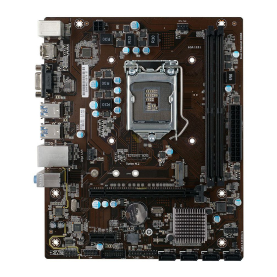
Page 9: Motherboard Components
Motherboard Components B250H4-M20 USER MANUAL... - Page 10 16. PCIEX16 PCI Express x16 Gen3 slot for graphics interface 17. M2 2242/2260/2280 supports PCI-E Gen 3 x 4 SSD & Intel® Optane Technology 18. SYS_FAN 4-pin System cooling fan connector 19. ATX_12V 4-pin +12V power connector B250H4-M20 USER MANUAL...
-
Page 11: I/O Ports
It can be connected to an external CD/DVD player, Tape player or other audio devices for audio input. 9. Line-out(lime) It is used to connect to speakers or headphones. 10. Microphone(pink) It is used to connect to a microphone. B250H4-M20 USER MANUAL... -
Page 12: Installing The Motherboard
Place the motherboard over the mounting brackets and secure the motherboard onto the mounting brackets with screws. Do not over-tighten the screws as this can stress the motherboard. B250H4-M20 USER MANUAL... -
Page 13: Checking Jumper Settings
The following illustration shows the location of the motherboard jumpers. Pin 1 is labeled. To avoid the system instability after clearing CMOS, we recommend users to enter the main BIOS setting page to “Load Default Settings” and then “Save and Exit Setup”. B250H4-M20 USER MANUAL... -
Page 14: Installing Hardware
Lift the tail of the load lever and rotate the load plate to fully open position. Grasp the edge of the package substrate. Make sure pin 1 indicator is on your bottom-left side. Aim at the socket and place the package carefully into the socket by purely vertical motion. B250H4-M20 USER MANUAL... - Page 15 Spreader). Engage the load lever while pressing down lightly onto the load plate. Secure the load lever with the hook under retention tab. Then the cover will flick automatically. Please save and replace the cover onto the CPU socket if processor is re- moved. B250H4-M20 USER MANUAL...
-
Page 16: Installing The Cpu Cooler
B. Fasten the cooling fan supporting base onto the CPU socket on the motherboard. And make sure the CPU fan is plugged to the CPU fan connector. C. Connect the CPU cooler power connector to the CPU_FAN connector. B250H4-M20 USER MANUAL... -
Page 17: Installing Memory Modules
The slot latche is levered upwards and latch on to the edges of the DIMM. * For reference only We suggest users not to mix memory type. It is recommended to use the same brand and type memory on this motherboard. B250H4-M20 USER MANUAL... -
Page 18: Installing Add-On Cards
This is M.2 slot, 2242/2260/2280 supports PCI-E Gen3 x 4 SSD & Intel ® Optane Technology. Before installing an add-on card, check the documentation for the card carefully. If the card is not Plug and Play, you may have to manually configure the card before installation. B250H4-M20 USER MANUAL... - Page 19 Please refer the following illustrations to install the add-on card: Install the VGA Card in the PCIEX16 slot Install the LAN Card in the PCIEX1 slot B250H4-M20 USER MANUAL...
- Page 20 Demount the screw not used according to the length of your M.2 SSD card. Insert the M.2 SSD card into M2 slot in the fool-proof way. Lock the screw as the following picture shows to make sure the M.2 SSD card is installed in place. B250H4-M20 USER MANUAL...
-
Page 21: Connecting Optional Devices
CASE USB3F SATA1~4 F_USB1~2 F_AUDIO 1. CASE: Chassis Intrusion Detect Header This detects if the chassis cover has been removed. This function needs a chassis equipped with instrusion detection switch and needs to be enabled in BIOS. B250H4-M20 USER MANUAL... - Page 22 USB connector to connect the front-mounted ports to the motherboard. Please make sure that the USB cable has the same pin assignment as indicated above. A different pin assignment may cause damage or system hang-up. B250H4-M20 USER MANUAL...
- Page 23 Please make sure that the USB cable has the same pin assignment as indicated above. A different pin assignment may cause damage or system hang-up. 5. COM: Onboard Serial Port Header Connect a serial port extension bracket to this header to add a serial port to your system. B250H4-M20 USER MANUAL...
- Page 24 97 Front Panel, please tick off the option of “ Disabled Front Panel Detect ”. If you use HD Audio Front Panel, please don’ t tick off “Disabled Front Panel Detect ” . * For reference only B250H4-M20 USER MANUAL...
- Page 25 If you use AC’ 97 Front Panel, please don’ t tick off “Using Front Jack Detect ”. If you use HD Audio Front Panel, please tick off the option of “Using Front Jack Detect ”. * For reference only B250H4-M20 USER MANUAL...
-
Page 26: Installing A Sata Hard Drive
Attach either cable end to the connector on the motherboard. Attach the other cable end to the SATA hard drive. Attach the SATA power cable to the SATA hard drive and connect the other end to the power supply. * For reference only B250H4-M20 USER MANUAL... -
Page 27: Connecting Case Components
2-4-7. Connecting Case Components After you have installed the motherboard into a case, you can begin connecting the motherboard components. Refer to the following: Components Components CPU_FAN ATX_POWER SYS_FAN F_PANEL ATX12V B250H4-M20 USER MANUAL... - Page 28 Users please note that the fan connector supports the CPU cooling fan of 1.1A ~ 2.2A (26.4W max) at +12V. 2. ATX_POWER (ATX 24-pin Power Connector) & 6. ATX12V (ATX 12V Power Connector) Connect the standard power supply connector to ATX_POWER. Connect the auxiliary case power supply connector to ATX12V. B250H4-M20 USER MANUAL...
-
Page 29: Front Panel Header
4-pin power cable 3. F_PANEL: Front Panel Header The front panel header (F_PANEL) provides a standard set of switch and LED headers commonly found on ATX or Micro ATX cases. Refer to the table below for information: B250H4-M20 USER MANUAL... - Page 30 After receiving a power on/off signal, at least two seconds elapses before the power supply recognizes another on/off signal. 4. BZ: Buzzer Header This concludes Chapter 2. The next chapter covers the BIOS. B250H4-M20 USER MANUAL...
- Page 31 Memo B250H4-M20 USER MANUAL...
-
Page 32: Using Bios
When you power on the system, BIOS enters the Power-On Self Test (POST) routines. POST is a series of built-in diagnostics performed by the BIOS. After the POST routines are completed, the following message appears: Press DEL to enter SETUP B250H4-M20 USER MANUAL... -
Page 33: Resetting The Default Cmos Values
Wrong” message. This standard message will appear following a clear CMOS data at factory by the manufacturer. You simply need to Load Default Settings to reset the default CMOS values. Note: Changes to system hardware such as different CPU, memories, etc. may also trigger this message. B250H4-M20 USER MANUAL... -
Page 34: Using Bios
BIOS setup screens shown in this chapter are for reference only and may differ from the actual BIOS. Please visit the manufacture’s website for updated manual. 2. In this Gui BIOS, you can operate by mouse or keyboard. Click : select item; Double click: enter; Right click: exit. B250H4-M20 USER MANUAL... - Page 35 Select the advanced icon and press <Enter> or double click the left key of the mouse to display the screen. Exit Select the exit icon and press <Enter> or double click the left key of the mouse to display the screen. B250H4-M20 USER MANUAL...
-
Page 36: Main Menu
The Date and Time items show the current date and time on the computer. If you are running a Windows OS, these items are automatically updated whenever you make changes to the Windows Date and Time Properties utility. BIOS Version (17.05.18) This item shows the BIOS version. B250H4-M20 USER MANUAL... -
Page 37: Advanced Menu
F1: General Help F2: Previous Values F3: Optimized Defaults F4: Save & Exit ESC/Right Click: Exit Onboard LAN Controller (Enabled) Use this item to enable or disable Onboard LAN controller. Press <Esc> to return to the Advanced Menu page. B250H4-M20 USER MANUAL... -
Page 38: Pc Health Status
F1: General Help F2: Previous Values F3: Optimized Defaults F4: Save & Exit ESC/Right Click: Exit Smart Fan Select (CPU Fan) This item allows you to change and configure Smart Fans on M/B. ex. CPU Fan, System Fan. B250H4-M20 USER MANUAL... - Page 39 • DIMM Voltage • +12V • +5VSB • +VCC TCC Activation Temperature (DTS) (100) This item is used to set the value from the factory TCC Activation Temperature. Press <Esc> to return to the Advanced Menu page. B250H4-M20 USER MANUAL...
-
Page 40: Power Management Setup
EUP Function (Enabled) This item allows user to enable or disable EUP support. Power LED Type (Dual Color LED) This item shows the type of the Power LED. Press <Esc> to return to the Advanced Menu page. B250H4-M20 USER MANUAL... -
Page 41: Acpi Settings
F4: Save & Exit ESC/Right Click: Exit ACPI Sleep State [S3(Suspend to RAM)] This item allows user to enter the ACPI S3 (Suspend to RAM) Sleep State (default). Press <Esc> to return to the Advanced Menu page. B250H4-M20 USER MANUAL... -
Page 42: Cpu Configuration
Use this item to control the number of active processor cores. Limit CPUID Maximum (Disabled) Use this item to enable or disable the maximum CPUID value limit, you can enables this item to prevent the system from “rebooting” when trying to install Windows NT 4.0. B250H4-M20 USER MANUAL... - Page 43 Use this item to enable or disable the Enhanced C1 state. Intel(R) Speed Shift Technology (Disabled) Use this item to enable the CPU energy-saving function when the system is not running. Press <Esc> to return to the Advanced Menu page. B250H4-M20 USER MANUAL...
-
Page 44: Sata Configuration
SATA Port 1~4 (Not Present) This motherboard supports four SATA channels, each channel allows one SATA device to be installed. Use these items to configure each device on the SATA channel. Press <Esc> to return to the Advanced Menu page. B250H4-M20 USER MANUAL... -
Page 45: Usb Configuration
All USB Devices (Enabled) Use this item to enable or disable all USB devices. Legacy USB Support (Enabled) Use this item to enable or disable support for legacy USB devices. Press <Esc> to return to the Advanced Menu page. B250H4-M20 USER MANUAL... -
Page 46: Super Io Configuration
This item allows you to enable or disable serial port. Device Settings (IO=3F8h; IRQ=4) This item shows the information of the device settings. Change Settings (Auto) Use this item to change device settings. Press <Esc> to return to the Super IO Configuration page. B250H4-M20 USER MANUAL... -
Page 47: Trusted Computing
Physical Presence Spec Version (1.3) Use this item to show the Physical Presence Spec Version. TPM 20 Interface Type (CRB) Use this item to select the communication interface to TPM 20 device. Press <Esc> to return to the Advanced Menu page. B250H4-M20 USER MANUAL... -
Page 48: Intel Rapid Storage Technology
Enter/Dbl Click : Select +/- : Change Opt. F1: General Help F2: Previous Values F3: Optimized Defaults F4: Save & Exit ESC/Right Click: Exit No disks connected to system This item shows your computer have disk or not. B250H4-M20 USER MANUAL... -
Page 49: Chipset Menu
When set to Fixed Mode, the graphics driver will reserve a fixed position of the system memory as graphics memory, according to system and graphics requirement. IGD Multi-Monitor (Disabled) This item allows you to enable or disable the IGD Multi-Monitor. Press <Esc> to return to the Tweak Menu page. B250H4-M20 USER MANUAL... - Page 50 Intel integrated Graphics and one or two PCI-Express graphics devices under Windows 10/8.x. Step 1. Insert ECS drives DVD to run Auto setup or browse the DVD to install Intel chipset drivers, VGA and sound drivers.(If you want know the detail information, please refer to chapter 4.)
- Page 51 DVMT/FIXED Memory 256M IGD Multi-Monitor Disabled : Select Screen /Click: Select Item Enter/Dbl Click : Select +/- : Change Opt. F1: General Help F2: Previous Values F3: Optimized Defaults F4: Save & Exit ESC/Right Click: Exit B250H4-M20 USER MANUAL...
-
Page 52: Display Devices
Extend desktop to this display You must select Apply before making additional changes. Disconnect this display Make this my main display Advance settings Make text and other items larger or smaller What display settings should I choose? Cancel Apply B250H4-M20 USER MANUAL... - Page 53 Multiple displays: Extend desktop to this display You must select Apply before making additional changes. Make this my main display Advance settings Make text and other items larger or smaller What display settings should I choose? Cancel Apply B250H4-M20 USER MANUAL...
-
Page 54: Pch Configuration
Use this item to enable or disable the warning if the case is opened up, and the item below indicates the current status of the case. Chassis Opened (No) This item indicates whether the case has been opened. Press <Esc> to return to the Tweak Menu page. B250H4-M20 USER MANUAL... - Page 55 F2: Previous Values F3: Optimized Defaults F4: Save & Exit ESC/Right Click: Exit ME Control (Enabled) Use this item to enable or disable the ME Firmware. ME FW Version (11.6.20.1221) This item shows the ME FW version. B250H4-M20 USER MANUAL...
-
Page 56: Tweak Menu
This item allows users to enable or disable the EIST (Enhanced Intel SpeedStep Technology). Power Limit 1 Override (Enabled) Use this item to enable or disable the Power Limit 1 Override. If this option is disabled, BIOS will program the default values for Power Limit 1. B250H4-M20 USER MANUAL... - Page 57 Use this item to enable or disable the Limit 3 Override. If this option is disabled, BIOS will leave the default values for Power Limit 3 and power limit 3 time window. Press <Esc> to return to the CPU OverClocking Configuration page. B250H4-M20 USER MANUAL...
- Page 58 CPU Ratio (40) This item allows you to control CPU ratio. 1 /2-Core Ratio Limit override (40) Use these items to set the Core Ratio Limit Value. Press <Esc> to return to the CPU OverClocking Configuration page. B250H4-M20 USER MANUAL...
-
Page 59: Security Menu
Secure Boot (Enabled) This item is used to control the secure boot flow, it is possible only if system runs in User Mode. Secure Boot Mode (Standard) This item is used to select the secure boot mode. B250H4-M20 USER MANUAL... -
Page 60: Boot Menu
Boot Option #1 /2 /3 /4 /5 /6 /7 These items show the boot priorities. UEFI USB Flash Drive Priorities This item enables you to specify the sequence of loading the operating system from the installing UEFI USB Flash drive. B250H4-M20 USER MANUAL... -
Page 61: Exit Menu
This item enables you to save the changes that you have made as user defaults. Restore User Defaults This item enables you to restore the user defaults. Boot Override Use this item to select the boot device. B250H4-M20 USER MANUAL... -
Page 62: Updating The Bios
BIOS jumper, reset the jumper to protect the newly installed BIOS from being overwritten. The computer will restart automatically. This concludes Chapter 3. Refer to the next chapter for information on the software supplied with the motherboard. B250H4-M20 USER MANUAL... - Page 63 Memo B250H4-M20 USER MANUAL...
-
Page 64: Using The Motherboard Software
Click Setup. The installation program begins: The following screens are examples only. The screens and driver lists will be different according to the motherboard you are installing. The motherboard identification is located in the upper left-hand corner. B250H4-M20 USER MANUAL... - Page 65 Windows 8 will show the following screen after system restart, you must select “Desktop” in the bottom left to install the next driver. B250H4-M20 USER MANUAL...
-
Page 66: Manual Installation
README.DOC) for information on installing the driver or software for your operating system. ECS Utility Software (Intelligent EZ Utility) ECS Intelligent EZ Utility provides friendly interfaces under Windows O.S, which makes your computing more easily and conveniently. These software(s) are subject to change at anytime without prior notice. Please refer to the support disk for available software. - Page 67 Just select the one you prefer and start to download and install the drivers. eBLU ECS eBLU utility makes BIOS update faster and easier. eBLU will list the latest BIOS with a default check-mark. Click”install” button to install. Microsoft .NET Framework 3.5 is required.
-
Page 68: Trouble Shooting
Before calling for technical support or returning for warranty, this chapter may help to address some of the common questions using some basic troubleshooting tips. You may also log onto our ECS website for more information: http:// www.ecs.com.tw/ECSWebSite/Support/Support_FAQ.aspx?MenulD=49& childid=M 49&LanlD=0 a) System does not power up and the fans are not running. -
Page 69: Start Up Problems After Prolong Use
5. Check whether there is any bulked up electrolytic capacitor or abnormal component. Please log onto our ECS website: http://www.ecs.com.tw/ECSWebSite/Support/ Technical_Support_List.aspx?MenuID=50&LanID=0 for more information. Maintenance and care tips Your computer, like any electrical appliance, requires proper care and maintenance. - Page 71 Memo B250AM4-M20 USER MANUAL...