Table of Contents
Advertisement
Quick Links
Advertisement
Table of Contents

Related Manuals for Omron V680-HA63A


Summary of Contents for Omron V680-HA63A
- Page 1 RFID System V680 Series User's Manual for Amplifiers, Antennas, and ID Tags (EEPROM) Amplifier and Antennas V680-HA63A V680-HS51 V680-HS52 V680-HS63 V680-HS65 V680-H01-V2 ID Tags V680-D1KP52MT V680-D1KP66T V680-D1KP66MT V680-D1KP66T-SP V680-D1KP58HT Cat. No.: Z262-E1-04...
- Page 2 Introduction Thank you for purchasing a V680-series RFID System. This manual describes the functions, performance, and application methods needed for optimum use of the V680-series RFID System. Please observe the following items when using the RFID System. • Allow the RFID System to be installed and operated only by qualified specialist with a sufficient knowledge of electrical systems.
- Page 3 READ AND UNDERSTAND THIS DOCUMENT Introduction Product Overview Section 1 Specifications and Performance Section 2 Communications Specifications Section 3 Installation Section 4 Chemical Resistance Section 5 RFID System V680-HA63A Amplifier V680-HS51 Antenna V680-HS52 Antenna V680-HS63 Antenna V680-HS65 Antenna V680-H01-V2 Antenna V680-D1KP52MT...
- Page 4 Please read and understand this document before using the products. Please consult your OMRON representative if you have any questions or comments. WARRANTY OMRON’s exclusive warranty is that the products are free from defects in materials and workmanship for a period of one year (or other period if specified) from date of sale by OMRON.
-
Page 5: Safety Precautions
Alert Symbols for Safe Use The following symbols are used in this manual to indicate precautions that must be observed to ensure safe use of the V680-HS51, V680-HS52, V680-HS63, V680-HS65, V680-H01-V2, V680-HA63A, V680- D1KP52MT, V680-D1KP66T, V680-D1KP66MT, V680-D1KP66T-SP, and V680-D1KP58HT. The precautions provided here contain important safety information. - Page 6 Por medio de la presente Omron declara que el RFID Sistema, V680-HS51 Serie, V680-HS52 Serie, V680-HS63 Serie, V680-HS65 Serie, V680-H01-V2 Serie, V680-HA63A Serie esta conforme a los requisitos esenciales y cualesquiera otras disposiciones aplicables o exigibles de la Directiva 1999/5/CE.
- Page 7 Introduction 5. China Amplifier Antenna CMII ID:2008DJ0884 V680-HA63A V680-HS51 CMII ID:2007DJ0577 V680-HA63A V680-HS52-R CMII ID:2007DJ0575 V680-HA63A V680-HS52-W CMII ID:2007DJ0571 V680-HA63A V680-HS63-R CMII ID:2007DJ0573 V680-HA63A V680-HS63-W CMII ID:2008DJ0141 V680-HA63A V680-HS65-R CMII ID:2008DJ0142 V680-HA63A V680-HS65-W 6. Korea Amplifier Antenna OMR-V680-HA63A V680-HA63A V680-HS51...
- Page 8 Antenna A011578 V680-HA63A V680-HS51 V680-HS52 V680-HS63 V680-HS65 If the product is used in Malaysia, a label must be attached on-site to the side of the V680-HA63A. Please consult your OMRON sales representative for details. 11.Philippine Amplifier Antenna ESD-0702971C V680-HA63A V680-HS51...
-
Page 9: Precautions For Safe Use
Attach a Setting switch protection Cover after setting Switch. 8. If an error is detected in any Product, immediately stop operation and turn OFF the power supply. Consult with an OMRON representative. 9. Dispose of the Products as industrial waste. -
Page 10: Precautions For Correct Use
Introduction Precautions for Correct Use Always observe the following precautions to prevent operation failures, malfunctions, and adverse effects on performance and equipment. 1. Installation Environment Do not use the Products in the following locations. • Locations exposed to direct sunlight •... - Page 11 5. Combination of the Amplifier • Use the V680-D1KP52MT, V680-D1KP66T, V680-D1KP66MT, and V680-D1KP66T-SP ID Tags in combination with only the V680-HA63A Amplifier. Do not use these ID Tags together with the V680- HA63B Amplifier. RFID System...
-
Page 12: Meanings Of Symbols
Introduction Meanings of Symbols Indicates particularly important points related to a function, including precautions and application advice. Indicates page numbers containing relevant information. RFID System User's Manual... -
Page 13: Table Of Contents
Introduction Table of Contents Safety Precautions Regulations and Standards Precautions for Safe Use Precautions for Correct Use Meanings of Symbols Table of Contents Section 1 Product Overview Features Product Configuration Section 2 Specifications and Performance Antennas with Separate Amplifier Antennas with Built-in Amplifier Amplifier Tags Section 3 Communications Specifications... - Page 14 Introduction MEMO RFID System User's Manual...
-
Page 15: Section 1 Product Overview
Section 1 Product Overview Features Product Configuration RFID System User's Manual... -
Page 16: Features
Section 1 Product Overview Features The V680-series RFID System actively supports many different types of system, such as distributed-control systems and many-product, small-lot production systems, with non-contact data communications using electromagnetic induction. Non-contact Data Communications The V680 Series uses electromagnetic induction to enable non-contact, bi-directional data communi- cations between Antennas and Tags. -
Page 17: Product Configuration
Transmission will not be possible if the V680-HS63 Antenna is used. Use the V680-D1KP52MT, V680-D1KP66T, V680-D1KP66MT, and V680-D1KP66T-SP ID Tags in combination with only the V680-HA63A Amplifier, Do not use these ID Tags together with the V680-HA63B Amplifier. RFID System... - Page 18 Section 1 Product Overview Using a V680-H01-V2 Antenna with Built-in Amplifier Personal computer Programmable Controller (SYSMAC CS/CJ Series) RS-232C RS-422 RS-485 V680-CA5D01-V CS1W-V680C11 CJ1W-V680C11 V700-A40-W * Always use the specified Cable to connect a V680-H01-V2 Antenna. The V680-H01-V2 Antenna cannot be connected without using the specified Cable.
-
Page 19: Section 2 Specifications And Performance
Section 2 Specifications and Performance Antennas with Separate Amplifier Antennas with Built-in Amplifier Amplifier Tags RFID System User's Manual... -
Page 20: Antennas With Separate Amplifier
Section 2 Specifications and Performance Antennas with Separate Amplifier V680-HS51 General Specifications Item Model V680-HS51 −10 to 60°C (with no icing) Ambient operating temperature −25 to 75°C (with no icing) Ambient storage temperature 35% to 95% (with no condensation) Ambient operating humidity Insulation resistance 20 MΩ... - Page 21 Section 2 Specifications and Performance V680-HS52 General Specifications Item Model V680-HS52-W V680-HS52-R (Standard cable, waterproof connector) (Flexible cable, non-waterproof connector) −10 to 60°C (with no icing) Ambient operating temperature −25 to 75°C (with no icing) Ambient storage temperature 35% to 95% (with no condensation) Ambient operating humidity Insulation resistance...
- Page 22 Section 2 Specifications and Performance • V680-HS52-R 22.5 dia. Two toothed washers Two lock nuts Mounting Hole Dimensions M22 × 1 Ferrite core Operation indicator Antenna Insulation cover Connector (39.5) 35 dia. 47.6 Insulation cover Coaxial cable, 5.3 dia., standard length: 2 m Case material Brass Communications...
- Page 23 Section 2 Specifications and Performance V680-HS63 General Specifications Item Model V680-HS63-W V680-HS63-R (Standard cable, waterproof connector) (Flexible cable, non-waterproof connector) −10 to 60°C (with no icing) Ambient operating temperature −25 to 75°C (with no icing) Ambient storage temperature Ambient operating 35% to 95% (with no condensation) humidity Insulation resistance...
- Page 24 Section 2 Specifications and Performance V680-HS63-R Antenna Ferrite core (Unit: mm) Connector (39.5) Insulation cover Coaxial cable, 5.3 dia., standard length: 2 m Operation indicator Note: Mounting Hole Dimensions Two, M4 or 4.5 dia. holes Coil center Case material ABS resin Fill resin Epoxy resin Cable...
- Page 25 Section 2 Specifications and Performance V680-HS65 General Specifications Item Model V680-HS65-W V680-HS65-R (Standard cable, waterproof connector) (Flexible cable, non-waterproof connector) −25 to 70°C (with no icing) Ambient operating temperature −40 to 85°C (with no icing) Ambient storage temperature 35% to 95% (with no condensation) Ambient operating humidity 20 MΩ...
- Page 26 Section 2 Specifications and Performance V680-HS65-R (Unit: mm) 90±0.2 4-4.5 dia. Operation indicator (Mounting holes) Ferrite core Connector (39.5) Bushing Insulation cover Coaxial cable, 5.3 dia., standard length: 2 m Case material ABS resin Fill resin Epoxy resin Cable PVC (black) RFID System User's Manual...
-
Page 27: Antennas With Built-In Amplifier
Section 2 Specifications and Performance Antennas with Built-in Amplifier V680-H01-V2 General Specifications Item Model V680-H01-V2 −10 to 55°C (with no icing) Ambient operating temperature −35 to 65°C (with no icing) Ambient storage temperature 35% to 85% (with no condensation) Ambient operating humidity Insulation resistance 20 MΩ... - Page 28 Section 2 Specifications and Performance Dimensions MOUNTING SCREW HOLES (Unit : mm) Connector Senter of Coil Vinyl Insulated Round Cord (5.8-dia.) (41/0.16-dia.) 2 Cores (17/0.08-dia.) 8 Cores Standard Length 0.5 m Four, M4 or 4.5-dia. holes 142.5 Twelve, Operation Indicator ±0.2 Four, 5-dia.
- Page 29 Section 2 Specifications and Performance Operation Indicator name Color Meaning Green Lit when the power is ON. COMM Yellow Lit when a command is being sent. NORM Green Lit when communications with a Tag are normal in Normal Communications Mode. Lit when an error occurs in communications with a Tag in Normal Communications Mode.
- Page 30 Section 2 Specifications and Performance Setting Switch Setting switch protection cover Note: Please attach a setting switch protection cover after setting switch. Setting Function Default setting SW1-1 Controller selection OFF:V680-CA5D01-V@, CS1W-V680C11, or CJ1W-V680C11 ON: V680-CA1D/-CA2D SW1-2 Reserved by System (Always set this Switch to OFF.) SW1-3 Reserved by System (Always set this Switch to OFF.) SW1-4...
- Page 31 Section 2 Specifications and Performance Cables (V680-H01-V2 exclusive use) Specifications Item Model V700-A40-W Number of conductors 10 Insulation resistance 5 MΩ min. (at 500 VDC) between terminals and sheath Dielectric strength 500 VAC, 1 min Dimensions Item Model V700-A40-W 2M V700-A40-W 5M V700-A40-W 10M V700-A40-W 20M...
-
Page 32: Amplifier
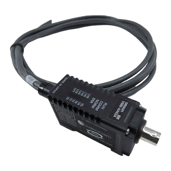
Section 2 Specifications and Performance Amplifier V680-HA63A General Specifications Item Model V680-HA63A −10 to 55°C (with no icing) Ambient operating temperature −25 to 65°C (with no icing) Ambient storage temperature 35% to 85% (with no condensation) Ambient operating humidity Insulation resistance 20 MΩ... - Page 33 Section 2 Specifications and Performance Nomenclature Antenna with Separate Amplifier connection port LV6/7D COMM LV5/7A NORM LV4/76 LV3/72 LV2/71 Operation indicators LV1/70 Controller connector Antenna Connection Port The Antenna connection port is connected a V680-series Antenna. Controller Connector The Controller connector is connected to Antenna connection port on the Controller. Operation Indicators (LEDs) Name Color...
- Page 34 Section 2 Specifications and Performance Cables (V680-HA63 exclusive use) Specifications Item Model V700-A43/V700-A44 Number of conductors 10 Insulation resistance 5 MΩ min. (at 500 VDC) between terminals and sheath Dielectric strength 500 VAC, 1 min Dimensions Item Model V700-A43 V700-A44 Length (L1) Approx.10m Approx.
-
Page 35: Tags
Section 2 Specifications and Performance Tags and Dimensions Specifications V680-D1KP52MT • General Specifications Item Model V680-D1KP52MT Memory capacity 1,000 bytes (user area) Memory type EEPROM Data backup time 10 years after writing (85°C or less), 0.5 years after writing (85°C to 125°C) Total data backup time at high temperatures exceeding 125°C is 10 houres (See note.) Memory longevity 100,000 times per block (25°C) - Page 36 Section 2 Specifications and Performance V680-D1KP66T/66MT • General Specifications Item Model V680-D1KP66T V680-D1KP66MT Memory capacity 1,000 bytes (user area) Memory type EEPROM Data backup time 10 years after writing (85°C or less), 0.5 years after writing (85°C to 125°C) Total data backup time at high temperatures exceeding 125°C is 10 houres (See note.) Memory longevity 100,000 times per block (25°C) −25 to 85°C (with no icing)
- Page 37 Section 2 Specifications and Performance • Dimensions V680-D1KP66T/66MT Four, R4 Four, R3 +0.2 Mounting Hole Dimensions Two, M3 +0.2 +0.2 Two, 3.5 dia. Two, 6 dia. +0.2 +0.1 Case material PPS resin V600-A86 Attachment Four, R5.5 Two, 4 dia. +0.2 Two, M3 +0.2 +0.2...
- Page 38 Section 2 Specifications and Performance V680-D1KP66T-SP • General Specifications Item Model V680-D1KP66T-SP Memory capacity 1,000 bytes (user area) Memory type EEPROM Data backup time 10 years after writing (85°C or less) Memory longevity 100,000 times per block (25°C) −25 to 70°C (with no icing) Ambient operating temperature when communicating...
- Page 39 Section 2 Specifications and Performance V680-D1KP58HT • General Specifications Item Model V680-D1KP58HT Memory capacity 1,000 bytes (user area) Memory type EEPROM Data backup time 10 years after writing (85°C or less), 2 years after writing (85°C to 110°C) Total data backup time at high temperatures exceeding 110°C is 10 houres (See note.) Memory longevity 100,000 times per block (25°C) −10 to 85°C (with no icing)
- Page 40 Section 2 Specifications and Performance • Tag Heat Resistivity • Storing Tags under high temperatures will adversely affect the performance of the internal parts and the service life of the Tags. • An LTPD of 10% was determined during the evaluation for Tags that reached the end of their life after testing under the following test conditions •...
- Page 41 Section 2 Specifications and Performance • Dimensions V680-D1KP58HT (Unit: mm) 10±0.2 60 dia. 80 dia 14 dia Case material PPS resin Two, R2 The side with the markings is the communications surface. Mount the Tag with this side facing the Antenna. V680-A80 (Attachment) This Attachment is specifically designed to secure V680-D1KP58HT Tags to the workpiece.
- Page 42 Section 2 Specifications and Performance Memory Map Data Address 0000 0001 0002 0003 User area 03E6 03E7 1 byte EEPROM is used as memory in the Tags. The memory capacity available to the user is 1,000 bytes, including 0000H to 0003H (the Write Protec- tion Setting Area).
- Page 43 Section 2 Specifications and Performance Write Protection Function The write protection function prevents important data, such as product information, stored in memory in a Tag from being inadvertently overwritten. After important data has been written to memory, it can be write-protected using the following method. The write protection function can be switched with SW4-7 (Write Protection Function Setting) of the V680-CA5D@@-V@ Controller or with word (Write Protection Function Setting) in the DM(m+2)CH Area words allocated to the C@1W- V680C@@ ID Sensor Unit.
- Page 44 Section 2 Specifications and Performance MEMO RFID System User's Manual...