Table of Contents
Advertisement
Quick Links
IMPORTANT MANUAL
OPERATOR'S MANUAL
MODEL:
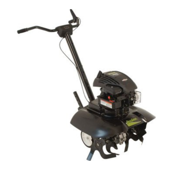
VF550
FRONT TINE TILLER
ALWAYS WEAR EYE PROTECTION DURING OPERATION
Visit our website: www.poulan.com
532 43 99-79
DO NOT THROW AWAY
WARNING:
Read this Man u al and follow all Warnings
and Safety Instructions. Fail ure to do so
can re sult in serious in ju ry.
12.21.10 CL
Printed in the U.S.A.
Advertisement
Table of Contents

Related Manuals for Poulan Pro Front Line Tiller VF550


Summary of Contents for Poulan Pro Front Line Tiller VF550
- Page 1 IMPORTANT MANUAL OPERATOR'S MANUAL MODEL: VF550 FRONT TINE TILLER ALWAYS WEAR EYE PROTECTION DURING OPERATION Visit our website: www.poulan.com 532 43 99-79 DO NOT THROW AWAY WARNING: Read this Man u al and follow all Warnings and Safety Instructions. Fail ure to do so can re sult in serious in ju ry.
-
Page 2: Safety Rules
Allow the engine to cool before storing in any enclosure. • Always refer to the operator’s guide instructions for im por tant details if the tiller is to be stored for an ex- tended period. - IMPORTANT - CAUTIONS, IMPORTANTS, AND NOTES ARE A MEANS OF ATTRACTING ATTENTION TO IMPORTANT OR CRIT I CAL IN FOR MA TION IN THIS MANUAL. -
Page 3: Table Of Contents
We have com pe tent, well-trained tech ni cians and the proper tools to service or repair this unit. Please read and retain this manual. The in struc tions will enable you to assemble and main tain your tiller prop erly. Always observe the “SAFETY RULES”. TABLE OF CONTENTS SAFETY RULES ... -
Page 4: Assembly
Your new tiller has been assembled at the factory with exception of those parts left unassembled for shipping purposes. To ensure safe and proper operation of your tiller all parts and hardware you assemble must be tightened securely. Use the correct tools as necessary ensure proper tightness. -
Page 5: Assembly
TO INSTALL DEPTH STAKE (See Fig. 4) • Remove screw(s) securing depth stake to skid and discard the screw(s). • Slide depth stake down into transport arm track, lin- ing up a hole in the depth stake with hole in transport arm. -
Page 6: Operation
Compare the illustrations with your tiller to familiarize yourself with the location of various controls and adjustments. Save this manual for future reference. These symbols may appear on your Tiller or in literature supplied with the product. Learn and understand their meaning. FORWARD TINE CONTROL DEPTH STAKE Our tillers conform to the safety standards of the American National Standards Institute. - Page 7 The operation of any tiller can result in foreign objects thrown into the eyes, which can result in severe eye damage. Always wear safety glasses or eye shields before starting your tiller and while tilling. We recommend a wide vision safety mask for over spectacles or standard safety glasses.
- Page 8 5. Grasp recoil starter handle with one hand and grasp tiller handle with other hand. Pull recoil starter handle quickly. Do not let starter rope snap back. NOTE: In cooler weather it may be necessary to repeat priming steps.
- Page 9 (The harder or wetter the ground, the slower the engine and tine speed needed. Under these poor con di tions, at fast speed the tiller will run and jump over the ground). A properly adjusted tiller will dig with little effort from the operator.
-
Page 10: Maintenance Schedule
3 - Initial oil change should be performed after first five (5) hours of operations. GENERAL RECOMMENDATIONS The warranty on this tiller does not cover items that have been subjected to operator abuse or negligence. To receive full value from the warranty, the operator must main tain tiller as instructed in this manual. -
Page 11: Maintenance
Change the oil after every 50 hours of operation or at least once a year if the tiller is not used for 50 hours in one year. Check the crankcase oil level before starting the engine and after each eight (8) hours of continuous use. - Page 12 Wa ter in en gine will short en the useful life of your tiller. COOLING FINS •...
-
Page 13: Service & Adjustments
SERVICE AND ADJUSTMENTS CAUTION: Disconnect spark plug wire from spark plug and place wire where it cannot come into contact with plug. TILLER TINE ARRANGEMENT Your outer tines can be assembled in several different ways to suit your tilling or cultivating needs. -
Page 14: Service & Adjustments
SERVICE AND ADJUSTMENTS TO REPLACE V-BELT (SEE Fig. 20 - 22) • Clutch housing/engine assembly must be removed to service belt. See "TO REMOVE CLUTCH HOUSINGI- ENGINE ASSEMBLY" in this section of manual. • Using pliers, remove cable spring and return spring from pivot bracket. -
Page 15: Storage
Immediately prepare your tiller for storage at the end of the season or if the unit will not be used for 30 days or more. WARNING: Never store the tiller with gasoline in the tank inside a build ing where fumes may reach an open flame or spark. -
Page 16: Troubleshooting
Ground too dry and hard. difficult handling Depth stake incorrectly adjusted. Soil balls up or clumps Ground too wet. Engine runs but tiller Tine control is not engaged. won’t move V-belt is off pulley(s). Engine runs but labors Tilling too deep. -
Page 17: Parts
DECALS KEY PART NO. NO. DESCRIPTION 532 43 00-07 Decal, Tine, Shield, Poulan 532 42 29-72 Decal, Tine, Shield, Warning 532 12 00-76 Decal, Warning, Rotating Tines 532 11 06-14 Decal, Hand Placement 532 43 99-79 Manual, Owner's (Eng/Fren) - Page 18 TILLER - - MODEL NUMBER VF550 (96082001501) ENGINE, TRANSMISSION, AND TINES engine-transmission-tines_1...
- Page 19 ENGINE, TRANSMISSION, AND TINES KEY PART NO. NO. DESCRIPTION - - - -- -- -- Engine B & S Model No. 10T802-1390-BI 872 11 06-08 Bolt Carriage 3/8 - 16 x 1 873 90 05-00 Nut Lock Flg 5/16 -18 unc 532 42 53-98 Plug Snap In 873 90 06-00...
- Page 20 TILLER - - MODEL NUMBER VF550 (96082001501) HANDLE, WHEEL, AND DEPTH STAKE Handles-Wheels-Depth Stake_1_r1.ai...
- Page 21 HANDLE, WHEEL, AND DEPTH STAKE KEY PART NO. NO. DESCRIPTION 532 43 62-80 Console Tiller Handle 532 16 57-87 Grip Handle 532 43 13-32 Assembly Handle Column 872 01 05-20 Bolt 5/16 - 18 x 2.50 532 19 19-38 Knob Wing...
-
Page 22: Parts And Service
PARTS AND SERVICE This product has been expertly en gi neered and carefully manu fac tured to rigid quality stan dards. As with all mechanical products, some adjustments or part replacement may be necessary during the life of your unit. For Parts and service, contact our authorized distributor: call 1-800-849-1297 •...