
Related Manuals for Stanley BR67


Summary of Contents for Stanley BR67
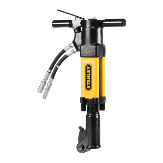
- Page 1 BR67 HYDRAULIC BREAKER USER MANUAL Safety, Operation and Maintenance © 2014 STANLEY Black & Decker, Inc. New Britain, CT 06053 U.S.A. 09278 11/2017 Ver. 27...
-
Page 2: Declaration Of Conformity
Disposizioni speciali: Misurazioni Representative in the Union: Patrick Vervier, Stanley Dubuis 17-19, rue Jules Berthonneau-BP 3406 41034 Blois Cedex, France. Vertreter in der Union/Représentant dans l’union/Representante en la Union/Rappresentante presso l’Unione Done at/Ort/Fait à/Dado en/Fatto a Stanley Infrastructure, Portland, Oregon USA... -
Page 3: Table Of Contents
REPAIRS AND / OR SERVICE TO THIS TOOL MUST ONLY BE DONE BY AN AUTHORIZED AND CERTIFIED DEALER. For the nearest certified dealer, call STANLEY Infrastructure at (503) 659-5660 and ask for a Customer Service Representative. BR67 User Manual ◄ 3... -
Page 4: Safety Symbols
Always observe safety symbols. They are included for your safety and for the protection of the tool. LOCAL SAFETY REGULATIONS Enter any local safety regulations here. Keep these instructions in an area accessible to the operator and maintenance personnel. 4 ► BR67 User Manual... -
Page 5: Safety Precautions
The BR67 Hydraulic Breaker will provide safe and de- • Do not exceed the rated limits of the tool or use the pendable service if operated in accordance with the in- tool for applications beyond its design capacity. - Page 6 Always de-energize the hydraulic system when rate and pressure rating. Rapid failure of the internal changing a tool bit. seals may result. • Take caution when changing a tool bit. Tool bits can get very hot. 6 ► BR67 User Manual...
-
Page 7: Tool Stickers & Tags
A HYDRAULIC LEAK OR BURST MAY CAUSE OIL INJEC- DO NOT CONNECT OPEN-CENTER TOOLS TO CLOSED- 74832 Decal STANLEY Logo (5.5” x 1.1” Black on Clear) TION INTO THE BODY OR CAUSE OTHER SEVERE CENTER HYDRAULIC SYSTEMS. THIS MAY RESULT IN PERSONAL INJURY. -
Page 8: Hose Types
HOSE SAFETY TAGS To help ensure your safety, the following DANGER tags are attached to all hose purchased from Stanley Hydraulic Tools. DO NOT REMOVE THESE TAGS. -
Page 9: Hose Recommendations
HOSE RECOMMENDATIONS BR67 User Manual ◄ 9... -
Page 10: Htma / Ehtma Requirements
2000 psi 2000 psi (at the power supply outlet) (172 bar) (138 bar) (138 bar) (138 bar) (138 bar) NOTE: These are general hydraulic system requirements. See tool specifi cation page for tool specifi c requirements 10 ► BR67 User Manual... -
Page 11: Operation
3. Place the bit firmly on the surface to be broken. 4. Squeeze the trigger to start the breaker. Adequate down pressure is very important. When the tool bit breaks through the obstruction or becomes bound, release the trigger and reposition the tool bit. BR67 User Manual ◄ 11... -
Page 12: Tool Protection & Care
Always replace hoses, couplings and other parts • Do not use the tool for applications for which it was with replacement parts recommended by STANLEY. not intended. Supply hoses must have a minimum working pressure rating of 2500 psi/172 bar. -
Page 13: Troubleshooting
(140 °F/60 °C max). Check the relief valve setting. Eliminate flow control devices. Fluid leakage on tool bit. Lower piston seal failure. Replace seal. Fluid leakage around trigger. Valve spool seal failure. Replace seals. BR67 User Manual ◄ 13... -
Page 14: Charging The Accumulator
2. Spray oil into the On/Off valve trigger slot area. 6. Install the plug. 3. Dip or spray the entire tool. 4. Cycle the tool hydraulically several times before storing away. 14 ► BR67 User Manual... - Page 15 CHARGING THE ACCUMULATOR Charging the Accumulator T-Handles Charging the Accumulator Anti-Vibration Handles BR67 User Manual ◄ 15...
-
Page 16: Specifications
Nominal Pressure ..........................1500 psi/103 bar Max Pressure ........................... 2500 psi/172 bar Max Relief Pressure ......................... 2150 psi/148 bar BR67 SOUND AND VIBRATION DECLARATION TEST CONDUCTED ON BR6717801,OPERATED AT STANDARD 8 GPM INPUT. MEASURED A-WEIGHTED SOUND POWER LEVEL, LWA (REF. 1PW) IN DECIBELS ......103 DBA UNCERTAINTY, KWA, IN DECIBELS ......................1.7 DBA... -
Page 17: Accessories
Accumulator Cylinder Puller ..............................05640 Accumulator Disassembly Tool .............................. 05508 Spacer (Flow Sleeve Installation) ............................04909 KITS Flow Sleeve Kit (See note on page 20 or page 22 for items included in kit) ................. 74396 BR67 User Manual ◄ 17... -
Page 18: Br67 Anti-Vib Parts Illustration
BR67 ANTI-VIB PARTS ILLUSTRATION BR67 ANTI-VIBRATION HANDLE PARTS ILLUSTRATION Coupler Set P/N-03971 See pages 23 through 28 for Breaker Foot Parts. 18 ► BR67 User Manual... -
Page 19: Br67 Anti-Vib Parts List
BR67 ANTI-VIB PARTS LIST BR67 ANTI-VIBRATION HANDLE PARTS LIST WITHOUT WITH WITHOUT WITH ITEM TRIGGER TRIGGER ITEM TRIGGER TRIGGER LOCK LOCK DESCRIPTION LOCK LOCK DESCRIPTION 24067 24067 RETAINING RING 04062 04062 BACK-UP WASHER 04055 04055 WASHER 03973 03973 MALE COUPLER BODY... - Page 20 BR67 ANTI-VIB PARTS LIST BR67 ANTI-VIBRATION HANDLE PARTS LIST (CONTINUED) WITHOUT WITH ITEM TRIGGER TRIGGER LOCK LOCK DESCRIPTION — 66828 TORSION SPRING (USED NOTE: There is a flow sleeve kit available ON TOOLS WITH AN “A” OR “AA” AT THE END OF THE...
-
Page 21: Br67 Std Parts Illustration
BR67 STD PARTS ILLUSTRATION BR67 STANDARD HANDLE PARTS ILLUSTRATION See pages 23 through 28 for Breaker Foot Parts. Coupler Set P/N-03971 BR67 User Manual ◄ 21... -
Page 22: Br67 Standard Parts List
04067 PUSH PIN and inst sheet. 07890 07890 ROLL PIN 04066 04066 AUTOMATIC VALVE BODY 04049 11435 HANDLE 04075 04075 SIDE ROD NUT — 28322 CE STICKER (CE ONLY) 28409 28409 COMPOSITE STICKER (CE ONLY) 22 ► BR67 User Manual... -
Page 23: Breaker Foot Assembly 05466
ASSEMBLY, PART NUMBER 05466) 04983 FOOT LATCH BOLT 04984 NYLOCK NUT 3/4-16 UNF 04985 SPRING WASHER 05466 SEAL INSERT (IF ORDERING SEAL INSERT, YOU MUST ORDER COMPLETE FOOT ASSEMBLY, PART NUMBER 05466) 08411 DETENT 34127 CUP SEAL BR67 User Manual ◄ 23... -
Page 24: Breaker Foot Assembly 05467
NUMBER 05467) 04983 FOOT LATCH BOLT 04984 NYLOCK NUT 3/4-16 UNF 04985 SPRING WASHER 05467 SEAL INSERT (IF ORDERING SEAL INSERT, YOU MUST ORDER COMPLETE FOOT ASSEMBLY, PART NUMBER 05467) 08411 DETENT 34127 CUP SEAL 24 ► BR67 User Manual... -
Page 25: Breaker Foot Assembly 07524
ORDER COMPLETE FOOT ASSEMBLY, PART NUMBER 07524) 07524 BREAKER FOOT (IF ORDERING FOOT, YOU MUST ORDER COMPLETE FOOT ASSEMBLY, PART NUMBER 07524) 07522 RETAINING RING 08116 COLLAR SUPPORT ASSY. 1/1/4” 08411 DETENT 34127 CUP SEAL BR67 User Manual ◄ 25... -
Page 26: Breaker Foot Assembly 07525
BUSHING, YOU MUST ORDER COMPLETE FOOT ASSEMBLY, PART NUMBER 07525) 07525 BREAKER FOOT (IF ORDERING FOOT YOU MUST ORDER COMPLETE FOOT ASSEMBLY, PART NUMBER 07525 07522 RETAINING RING 08115 COLLAR SUPPORT ASSY. 08411 DETENT 34127 CUP SEAL 26 ► BR67 User Manual... -
Page 27: Breaker Foot Assembly 08855
SEAL INSERT (IF ORDERING SEAL INSERT, YOU MUST ORDER COMPLETE FOOT ASSEMBLY, PART NUMBER 08855) 08855 BREAKER FOOT U/W (IF ORDERING SEAL FOOT YOU MUST ORDER COMPLETE FOOT ASSEMBLY, PART NUMBER 08855) 08411 DETENT 34127 CUP SEAL BR67 User Manual ◄ 27... -
Page 28: Breaker Foot Assembly 11236
(IF ORDERING HEX BUSHING, YOU MUST ORDER COMPLETE FOOT ASSEMBLY, PART NUMBER 11236) 11234 COLLAR SUPPORT ASSY. 11236 BREAKER FOOT (IF ORDERING FOOT YOU MUST ORDER COMPLETE FOOT ASSEMBLY, PART NUMBER 11236) 34127 CUP SEAL 28 ► BR67 User Manual... -
Page 29: Underwater Tools Depth Guideline
ROV operation is still limited to the tool, for Depth (ft) 8 GPM 12 GPM example a percussive tool has the same depth 5/8” 5/8” limitation whether ROV or diver operated. 3/4” 1” 1” 1” 1000 1” 1-1/4” BR67 User Manual ◄ 29... - Page 30 NOTES 30 ► BR67 User Manual...
- Page 32 STANLEY Infrastructure 6430 SE Lake Road Portland, Oregon 97222 USA (503) 659-5660 / Fax (503) 652-1780 www.stanleyinfrastructure.com...