Table of Contents
Advertisement
Quick Links
Traulsen Refrigeration
SERVICE MANUAL #07
Instructions For The Installation,
Troubleshooting And Repair Of Traulsen
®
epicon
Equipped Blast Chiller Models
Undercounter Model TBC5
Reach-In Model TBC13
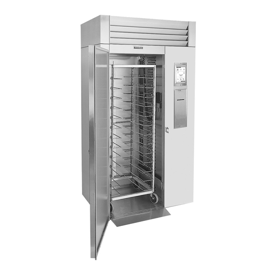
Roll-In/Roll-Thru Models TBC1H, TBC1HR, TBC2H & TBC2HR
-NOTICE-
This Manual is prepared for the use of trained Authorized Traulsen Service Agents and should not be used by
those not properly qualified. This manual is not intended to be all encompassing, but is written to supplement
the formal training, on-the-job experience and other product knowledge acquired by Authorized Traulsen
Service Agents. Before proceeding with any work, you should read, in its entirety, the repair procedure you
wish to perform to determine if you have the necessary tools, instruments and skills required to perform
the procedure. Procedures for which you do not have the necessary tools, instruments and skills should
be performed only by a trained Authorized Traulsen Service Agent.
Reproduction or other use of this Manual, without the express written consent of Traulsen, is prohibited.
FORM NUMBER TR99999 - REV. 8/13
Advertisement
Table of Contents
Troubleshooting

Related Manuals for Traulsen TBC13


Summary of Contents for Traulsen TBC13
- Page 1 Roll-In/Roll-Thru Models TBC1H, TBC1HR, TBC2H & TBC2HR -NOTICE- This Manual is prepared for the use of trained Authorized Traulsen Service Agents and should not be used by those not properly qualified. This manual is not intended to be all encompassing, but is written to supplement the formal training, on-the-job experience and other product knowledge acquired by Authorized Traulsen Service Agents.
-
Page 2: Table Of Contents
System (BC compressor on TBC1H only) c- IDLE Mode d- Hold Mode e-By Time Chill/Freeze Mode f-By Temp Chill/Freeze Mode g-By Product Chill/Freeze Mode h-Defrost Mode` Visit the Resource Center @ www.traulsen.com to review the Operator’s Video for this product. -
Page 3: General Information
Traulsen product, as well as the model and serial number. II. b - OPERATION: This tag is located inside all blast chiller models. An ex- Refer to the instructions contained in the Owner’s... -
Page 4: Specifications / Operating Data
3= Varies with remote system. III. c - REFRIGERATION SYSTEM INSTALLATION: All Traulsen blast chillers, with the exception of model TBC5, require the use of a floor drain or floor mounted condensate evaporator for condensate removal. Refer to Section IV. h of the blast chill owner’s manual for more information. -
Page 5: Servicing The Epicon Control
IV. SERVICING THE EPICON CONTROL IV. a - OVERVIEW: IV. c - SETTING THE CLOCK (continued): Traulsen’s TBC Series blast chillers are equipped with To adjust the Date and time settings: the epicon microprocessor control. This is protected from damage by a surrounding heavy gauge metal be- 1) Press DAY - MONTH - zel. -
Page 6: E-Service Menu Features
Normal readings for each OUTPUT should be... The current software versions are displayed at the top of the TOOLBOX main menu. Contact Traulsen at (800) LS EVAP FANS = 3.7A +/- .55A 825-8220 to verify if you have the latest software versions. -
Page 7: Control Architecture
V. CONTROL ARCHITECTURE LEGEND 1. UI Power 5. Label Printer Communication 2. USB Port (used) 6. Paper Printer Power 3. USB Port (unused) 7. Paper Printer Communica- tion 4. Label Printer Power... -
Page 8: Component Function
VI. COMPONENT FUNCTION Compressor Pumps refrigerant through refrigeration lines and components. Condenser Fan Draws air across condenser coil to aid in removing heat from the refrigerant and moves air across compressor to aid in cooling the compressor. Dual Pressure Control Low side monitors suction pressure at compressor. -
Page 9: Sequence Of Operation
VII. SEQUENCE OF OPERATION VII. a - REFRIGERATION SYSTEM - HOLD MODE: VII. d - HOLD MODE (cont’d): 1. The controller monitors the air temperature and 1. Unit is in IDLE mode. senses a need for cooling. 2. Hold mode is initiated. a) The relay that controls the compressor is NOTE: When the hold mode is initiated, two timers energized. -
Page 10: F-By Temp Chill/Freeze Mode
VII. SEQUENCE OF OPERATION (cont’d) VIII. SERVICE PROCEDURES VII. f - CHILL OR FREEZE MODE BY TEMP (cont’d): VIII. a - TEMPERATURE AIR SENSORS: NOTE: Once the temperature of the probe reaches WARNING: DISCONNECT THE ELECTRICAL POWER the target temperature the display will alternate with TO THE MACHINE AND FOLLOW LOCKOUT/TAGOUT PROCEDURES. -
Page 11: C-Door Perimeter Heaters
VIII. SERVICE PROCEDURES (cont’d) VIII. b - EXPANSION VALVE (cont’d): VIII. c - DOOR PERIMETER HEATERS (TBC1H, TBC1HR, TBC2H and TBC2HR only): WARNING: DISCONNECT THE ELECTRICAL POWER TO THE MACHINE AND FOLLOW LOCKOUT/TAGOUT PROCEDURES. 1. Remove the breaker caps from around the perimeter of the door opening. -
Page 12: E-Condenser Fan Assembly
VIII. SERVICE PROCEDURES (cont’d) VIII. d - COMPRESSOR (cont’d): VIII. f - CONDENSER COIL (cont’d): 2. Disconnect lead wires and conduit at the 2. Remove fan guard and fan shroud from compressor junction box. condensing coil. 3. Disconnect suction and discharge lines from the 3. -
Page 13: H-Evaporator Coil
OF REFRIGERANTS. BE CERTAIN THE WORK AREA IS 2. Remove the tray slides and pilasters from the WELL VENTILATED. SAFETY GOGGLES AND GLOVES interior (TBC5 and TBC13 only). SHALL BE WORN SINCE REFRIGERANTS MAY CAUSE 3. Remove the evaporator cover and open the INJURY TO THE SKIN. -
Page 14: K-Checking For Leaks
VIII. SERVICE PROCEDURES (cont’d) IX. l - EVACUATING THE SYSTEM: IX. k - CHECKING FOR LEAKS: WARNING: DISCONNECT THE ELECTRICAL POWER WARNING: DISCONNECT THE ELECTRICAL POWER TO THE MACHINE AND FOLLOW LOCKOUT/TAGOUT TO THE MACHINE AND FOLLOW LOCKOUT/TAGOUT PROCEDURES. PROCEDURES. WARNING: THIS PROCEDURE REQUIRES THE USE WARNING: THIS PROCEDURE REQUIRES THE USE OF REFRIGERANTS. -
Page 15: M-Charging The System
VIII. SERVICE PROCEDURES (cont’d) IX. m - CHARGING SYSTEM: IX. n - SYSTEM CLEAN UP/INTRODUCTION (cont’d): WARNING: DISCONNECT THE ELECTRICAL POWER WARNING: DISCONNECT THE ELECTRICAL POWER TO THE MACHINE AND FOLLOW LOCKOUT/TAGOUT TO THE MACHINE AND FOLLOW LOCKOUT/TAGOUT PROCEDURES. PROCEDURES. WARNING: THIS PROCEDURE REQUIRES THE USE OF WARNING: THIS PROCEDURE REQUIRES THE USE OF REFRIGERANTS. -
Page 16: O-Replacing The Door Gasket
VIII. SERVICE PROCEDURES (cont’d) IX. o - REPLACING DOOR GASKETS: WARNING: DISCONNECT THE ELECTRICAL POWER TO THE MACHINE AND FOLLOW LOCKOUT/TAGOUT PROCEDURES. NOTE: Before attempting to install a new gasket, both the unit and the gasket itself should remain at room temperature for at least 48 hours (especially in a low temperature area). -
Page 17: Wiring Diagrams - Tbc5
IX. WIRING DIAGRAM - MODEL TBC5 -16-... -
Page 18: Wiring Diagrams - Tbc13
X. WIRING DIAGRAM - MODEL TBC13 -17-... -
Page 19: Wiring Diagrams - Tbc1H Models
XI. WIRING DIAGRAM - MODEL TBC1H/TBC1HR -18-... -
Page 20: Troubleshooting
XII. TROUBLESHOOTING SYMPTOM POTENTIAL CAUSE SOLUTION No display on control. a. No power to unit. Check power supply and circuit breaker. b. System problem. Call for service. Batch requires too much a. Door not closed properly. Close door completely. time to chill product down b. -
Page 21: Xii. Troubleshooting
XII. TROUBLESHOOTING (cont’d) SYMPTOM POTENTIAL CAUSE SOLUTION 15. Low suction pressure. a. Solenoid valve restricted. Remedy solenoid restriction. b. Restriction in filter/drier. Replace filter/drier. c. Loss of refrigerant. Diagnose leak and recharge system. d. Poor air flow. Insure proper air flow around system. e. -
Page 22: Tbc5 Replacement Parts List
XIII. TBC5 REPLACEMENT PARTS LIST Description Part Number Quantity Door Assembly with Lock 200-60791-01 Door Hinge 282543 Door Gasket 341-60197-00 Lock Cylinder 358-13186-42 Lock Clip 358-13190-00 Lock Bolt 358-60023-00 Lock Key 358-28924-42 Tray Slide 340-60240-00 Front Pilaster 342-60077-00 Rear Pilaster 342-60078-00 Casters (without brake) 348-10012-00... -
Page 23: Tbc13 Replacement Parts List
XIV. TBC13 REPLACEMENT PARTS LIST Description Part Number Quantity Door Assembly Hinged Right 200-60763-00 Door Assembly Hinged Left 200-60763-01 Door Hinge Body 344-28482-00 Door Hinge Cover 344-28486-00 Door Hinge Bracket 344-28487-00 Door Hinge Cam 344-28488-00 Door Gasket 341-60223-00 Lock Cylinder... -
Page 24: Tbc1H Replacement Parts List
XV. TBC1H, TBC1HR, TBC2H & TBC2HR REPLACEMENT PARTS LIST TBC1H TBC2H TBC1HR TBC2HR Description Part Number Qty. Qty. Door Assembly Hinged Left 200-60802-00 Door Hinge Body 344-28482-00 Door Hinge Cover 344-28486-00 Door Hinge Bracket 344-28487-00 Door Hinge Cam 344-28488-00 Door Gasket 341-60225-00 Lock Cylinder 358-13186-42... - Page 25 -24-...
- Page 26 Traulsen 4401 Blue Mound Road Fort Worth, TX 76106 Phone: (800) 825-8220 Fax-Svce: (817) 740-6757 Website: www.traulsen.com Quality Refrigeration HOURS OF OPERATION: Monday thru Friday 7:30 am - 4:30 pm CST...