WAGNER ZIP52 Finishing Operating Manual
Pneumatic double
diaphragm pump
spray pack
Hide thumbs
Also See for ZIP52 Finishing:
- Instruction manual (90 pages) ,
- Operating manual (76 pages) ,
- Translation of the original operating manual (76 pages)
Table of Contents
Advertisement
Quick Links
Download this manual
See also:
Instruction Manual
Advertisement
Table of Contents

Related Manuals for WAGNER ZIP52 Finishing


Summary of Contents for WAGNER ZIP52 Finishing
- Page 1 Translation of the Original Operating Manual Version 12 / 2012 Pneumatic Double Diaphragm Pump Spray Pack B_04044 B_04045 B_04043...
-
Page 3: Table Of Contents
Safety Instructions for the Operator 4.1.1 Electrical Equipment 4.1.2 Personnel Qualifi cations 4.1.3 Safe Work Environment Safety Instructions for Staff 4.2.1 Safe Handling of WAGNER Spray Units 4.2.2 Earthing the Unit 4.2.3 Material Hoses 4.2.4 Cleaning 4.2.5 Handling Hazardous Liquids, Varnishes and Paints 4.2.6... - Page 4 Replacement of the Reversing Valve Material Hoses Decommisioning ACCESSORIES SPARE PARTS 11.1 How can Spare Parts be Ordered? 11.2 ZIP52 Finishing 11.3 ZIP52 PF Eco-Finishing – Aluminium 11.4 ZIP52 Pump – Metal 11.5 ZIP52 Pump - Conductive Acetal 11.6 ZIP Motor 11.7...
-
Page 5: About These Instructions
VERSION 12 / 2012 ORDER NUMBER DOC 2332848 OPERATING MANUAL ABOUT THESE INSTRUCTIONS PREFACE The operating manual contains information about safely operating, maintaining, cleaning and repairing the device. The operating manual is part of the device and must be available to operating and service staff . -
Page 6: Languages
VERSION 12 / 2012 ORDER NUMBER DOC 2332848 OPERATING MANUAL LANGUAGES The operating manual is available in the following languages: Language: Order No. Language: Order No. German 2332847 English 2332848 Italian 2332849 French 2335763 Spanish 2335762 ABBREVIATIONS IN THE TEXT Number of pieces Position Labeling in the spare parts lists... -
Page 7: Correct Use
VERSION 12 / 2012 ORDER NUMBER DOC 2332848 OPERATING MANUAL CORRECT USE DEVICE TYPES A) Metallic versions (aluminium and stainless steel): Pneumatic double diaphragm pumps with order number Aluminum Stainless steel Aluminum U760.00 U765.00 U731.00 B) Conductive acetal versions: Pneumatic double diaphragm pumps with order number (POM) acetal U773.00 TYPE OF USE... -
Page 8: Safety Parameters
OPERATING MANUAL SAFETY PARAMETERS WAGNER accepts no liability for any damage arising from incorrect use. Use the unit only to work with the materials recommended by WAGNER. Operate only the entire unit. Do not deactivate safety fi xtures. Use only WAGNER original spare parts and accessories. -
Page 9: Reasonably Foreseeable Misuse
Wagner double diaphragm pumps are not designed for pumping food. RESIDUAL RISKS Residual risks are risks which cannot be excluded even in the event of correct use. -
Page 10: Identification
VERSION 12 / 2012 ORDER NUMBER DOC 2332848 OPERATING MANUAL IDENTIFICATION EXPLOSION PROTECTION IDENTIFICATION Metallic (aluminium and stainless steel) and conductive acetal versions: Pneumatic double diaphragm pumps with order number Aluminium Stainless steel (POM) acetal Aluminum U760.00 U765.00 U773.00 U731.00 As defi ned in the Directive 94/9/EC (ATEX 95), the unit is suitable for use in areas where there is an explosion hazard. -
Page 11: General Safety Instructions
VERSION 12 / 2012 ORDER NUMBER DOC 2332848 OPERATING MANUAL GENERAL SAFETY INSTRUCTIONS SAFETY INSTRUCTIONS FOR THE OPERATOR Keep this operating manual at hand near the device at all times. Always follow local regulations concerning occupational safety and accident prevention. 4.1.1 ELECTRICAL EQUIPMENT Electrical devices and equipment... -
Page 12: Safety Instructions For Staff
The liquid emitters are to be checked for safe working conditions by an expert (e.g. Wagner Service Technician) as often as necessary or at least every 12 months, in accordance with the guidelines for liquid emitters (ZH 1/406 and BGR 500 Part 2 Chapter 2.36). -
Page 13: Material Hoses
VERSION 12 / 2012 ORDER NUMBER DOC 2332848 OPERATING MANUAL 4.2.3 MATERIAL HOSES Ensure that the hose material is chemically resistant to the sprayed materials. Ensure that the material hose is suitable for the pressure generated in the unit. Make sure that the hoses are laid only in suitable places. In no case, should hoses be laid in the following places: –... -
Page 14: Touching Hot Surfaces
VERSION 12 / 2012 ORDER NUMBER DOC 2332848 OPERATING MANUAL 4.2.6 TOUCHING HOT SURFACES Touch hot surfaces only if you are wearing protective gloves. When operating the unit with a coating material with a temperature of > 43 °C; 109.4 °F: - Identify the unit with a warning sticker "Warning - hot surface". -
Page 15: Tightness Check
4.3.1 SAFETY REGULATIONS Safe handling of WAGNER spray units Mechanical sparks can form if the unit comes into contact with metal. In an explosive atmosphere: Do not knock or push the unit against steel or rusty iron. -
Page 16: Operation Without Fluid
VERSION 12 / 2012 ORDER NUMBER DOC 2332848 OPERATING MANUAL Cleaning If there are deposits on the surfaces, the unit may form electrostatic charges. Flames or sparks can form during discharge. Remove deposits from the surfaces to maintain conductivity. Use only a damp cloth to clean the unit. 4.3.2 OPERATION WITHOUT FLUID Avoid running the pump sucking air, without fl uid inside. -
Page 17: Description
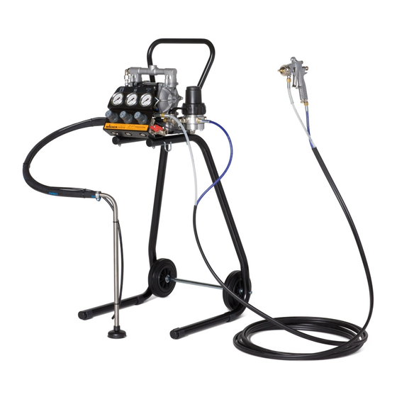
- Diaphragm pump - Suction hose with fi lter - On ZIP52 Finishing: Fine-Flow Controller FFC (precisely adjustable fi lter fl ow controller with fi lter and integrated pulsation damper) - On ZIP52PF Eco-Finishing: Materialfi lter (as an alternative to the above-mentioned FFC) -
Page 18: Technical Data
VERSION 12 / 2012 ORDER NUMBER DOC 2332848 OPERATING MANUAL 5.3.2 TECHNICAL DATA Description Unit U760.00 U765.00 U773.00 U731.00 Wetted parts materials Stainless Conductive Aluminum Aluminum steel acetal Transmission ratio Flow volume per double stroke cm³ (DH) Maximum operating pressure Maximum possible speed DH/min Maximum fl ow rate... - Page 19 VERSION 12 / 2012 ORDER NUMBER DOC 2332848 OPERATING MANUAL WARNING Outgoing air containing oil! Risk of poisoning if inhaled. Air motor switching problems. Provide compressed air free from oil and water (Quality Standard 5.5.4 according to ISO 8573.1) 5.5.4 = 40 μm / +7 / 5 mg/m³.
-
Page 20: Dimensions And Connections
VERSION 12 / 2012 ORDER NUMBER DOC 2332848 OPERATING MANUAL 5.3.3 DIMENSIONS AND CONNECTIONS D (x4) B_04046 ZIP52 Finishing on the trolley B_04047... - Page 21 VERSION 12 / 2012 ORDER NUMBER DOC 2332848 OPERATING MANUAL B_04048 Finishing on the Eco-Finishing trolley mm; inch mm; inch mm; inch 280.0; 11.02 520.0; 20.47 405.0; 15.94 189.0; 7.44 481.0; 18.94 335.0; 13.19 15.0; 0.59 1015.0; 39.96 940.0; 37.01 ø9.0;...
-
Page 22: Performance Diagrams
VERSION 12 / 2012 ORDER NUMBER DOC 2332848 OPERATING MANUAL 5.3.4 PERFORMANCE DIAGRAMS Example Material fl ow volume - water l/min <gpm> Diagram ZIP52 bar (MPa) nl/min <psi> <scfm> 10 (1.0) <145> <26.9> 8.0 (0.8) <21.4> <116> 6.0 (0.6) <16.1> <87>... - Page 23 VERSION 12 / 2012 ORDER NUMBER DOC 2332848 OPERATING MANUAL Diagram ZIP52 PF bar (MPa) nl/min <psi> <scfm> 10 (1.0) <145> <8.9> 8.0 (0.8) <7.1> <116> 6.0 (0.6) <5.4> <87> 4.0 (0.4) <3.6> <58> 2.0 (0.2) <1.8> <29> l/min <1.32> <2.64>...
-
Page 24: Mode Of Operation
VERSION 12 / 2012 ORDER NUMBER DOC 2332848 OPERATING MANUAL MODE OF OPERATION B_04006 Double diaphragm pump - operating principle The double diaphragm pump is driven with compressed air. Two diaphragms (A) are mechanically connected to each other by means of a shaft (B). Each diaphragm generates two chambers: pumping chamber (P) and motor chamber (M). -
Page 25: Assembly And Commissioning
VERSION 12 / 2012 ORDER NUMBER DOC 2332848 OPERATING MANUAL ASSEMBLY AND COMMISSIONING TRANSPORTATION The pump may be moved manually, without lifts and cranes. STORAGE Store the pump in a closed and dry environment. Thoroughly clean the pump, if a long-term decommissioning is planned. When resuming pump operation, proceed as described in the following sections. - Page 26 VERSION 12 / 2012 ORDER NUMBER DOC 2332848 OPERATING MANUAL Material connection: Connect the suction hose (on the underside) and the paint/air double hose to the corresponding connections. Note: Make sure that the color hose does not get mixed up with the air hose, as the connections are the same size.
-
Page 27: Grounding
VERSION 12 / 2012 ORDER NUMBER DOC 2332848 OPERATING MANUAL GROUNDING WARNING Discharge of electrostatically charged components in atmospheres containing solvents! Explosion hazard from electrostatic sparks. Clean the pump only with a damp cloth. WARNING Heavy paint mist if grounding is insuffi cient! Danger of poisoning. - Page 28 VERSION 12 / 2012 ORDER NUMBER DOC 2332848 OPERATING MANUAL The ground connection is imperative. B_04049 Procedure: 1. Remove the crimp connection delivered with the pump. 2. Crimp the grounding cable on the terminal and screw it back onto the pump’s foot. 3.
-
Page 29: Commissioning
Emergency stop In the case of unforeseen occurrences close the air cut-off valve immediately and open the return valve (if installed) and/or delivery devices (valves or guns). Zip52 Finishing An air cut-off valve is installed. ZIP52 PF Eco-Finishing An air cut-off valve must be provided by the user. -
Page 30: Preliminary Operations
Ensure that: - The pressure regulator knob is turned fully counterclockwise (0 bar pressure). - The air cut-off valve is closed. - The material return valve is opened. ZIP52 Finishing Pump pressure regulator Material pressure regulator Atomizing air pressure regulator... -
Page 31: Unit Pressure Tightness Test
OPERATING MANUAL Open the air supply and turn the pump's regulator knob clockwise until the pump starts. Set the material pressure regulator (if available - ZIP52 Finishing) to 1-2 bar. Don't let the pump run too quickly while priming. Subsequently, close the return valve. -
Page 32: Operation
VERSION 12 / 2012 ORDER NUMBER DOC 2332848 OPERATING MANUAL OPERATION OPERATION Priming: Make sure that the air pressure regulator knob is turned fully counterclockwise (0 bar pressure). Open the air cut-off valve and the spray gun. Increase the air pressure until the pump starts. -
Page 33: Ending Or Interrupting Work
VERSION 12 / 2012 ORDER NUMBER DOC 2332848 OPERATING MANUAL The atomizing air pressure should be set to 1-2.5 bar, depending on the paint characteristics. To obtain perfect atomization and to avoid spray mist, the lowest possible atomizing air pressure should be used. In very few cases, the gun must be provided with a very low material pressure and a very high atomizing air pressure. -
Page 34: Ending Work: Cleaning
VERSION 12 / 2012 ORDER NUMBER DOC 2332848 OPERATING MANUAL ENDING WORK: CLEANING Make sure to fl ush the pump out carefully at the end of the working session. Once fi nished spraying, decrease the atomization air pressure to zero. Reduce the air pressure to 2.5 bar. -
Page 35: Trouble Shooting And Rectification
Check the compressed air quality. outlet pipes. Install a condensation separator on the air line. Install an air dryer if necessary. Fill one lubricant with special de-icing fl uid. If the problem is not listed above, consult your WAGNER Service Center. -
Page 36: Cleaning And Maintenance
In accordance with the guideline for liquid emitters (ZH 1/406 and BGR 500 Part 2 Chapter 2.3): - The liquid emitters should be checked by an expert (e.g. Wagner service technician) for their safe working conditions as required and at least every 12 months. -
Page 37: Safety Instructions
This pump has one fi lter inside the suction pipe and another inside the delivery circuit (Fine-Flow Controller for the ZIP52 Finishing and fi lter for the ZIP52PF Eco-Finishing). All fi lters must be cleaned frequently. It is also necessary to clean the fi lters when changing the paint color. - Page 38 VERSION 12 / 2012 ORDER NUMBER DOC 2332848 OPERATING MANUAL Fine Flow Controller (ZIP52 Finishing) To clean the fi lter of the Fine-Flow controller, unscrew the plastic ring nut (1) from the metal body, lift the cup (2) paying attention to the PTFE gasket on the edge.
-
Page 39: Diaphragm Replacement (Preventive Maintenance)
VERSION 12 / 2012 ORDER NUMBER DOC 2332848 OPERATING MANUAL DIAPHRAGM REPLACEMENT (PREVENTIVE MAINTENANCE) Mark the coupled parts (Diaphragm covers, distributor, covers) with a felt-tip pen so as to make subsequent reassembly easier. a) Remove the suction and delivery manifolds. B_04015 b) Disassemble the fastening nuts and remove the outer diaphragm covers. - Page 40 VERSION 12 / 2012 ORDER NUMBER DOC 2332848 OPERATING MANUAL c) Hold the end nut of the one outer diaphragm disc with a wrench. Loosen the end nut of the other diaphragm disc and dismantle it. d) Remove the released diaphragm with its corresponding internal disc, and remove the shaft from the motor block.
-
Page 41: Diaphragm Replacement (Due To Breakage)
VERSION 12 / 2012 ORDER NUMBER DOC 2332848 OPERATING MANUAL DIAPHRAGM REPLACEMENT (DUE TO BREAKAGE) If the diaphragms are replaced as a result of breakage, all the internal parts of the motor must be cleaned and the condition of the seals and reversing valve, which may have been damaged by contact with the pump 3.5 Nm... -
Page 42: Cleaning / Replacement Of The Suction And Delivery Ball Valves
VERSION 12 / 2012 ORDER NUMBER DOC 2332848 OPERATING MANUAL CLEANING / REPLACEMENT OF THE SUCTION AND DELIVERY BALL VALVES a) Remove the suction and delivery manifold. b) Remove the seals, seats and balls from the diaphragm covers and the manifolds' h ousings. c) Check the condition of wear of the ball guide/stops inside the diaphragm covers and manifolds. -
Page 43: Decommisioning
VERSION 12 / 2012 ORDER NUMBER DOC 2332848 OPERATING MANUAL DECOMMISIONING When the equipment must be scrapped, please diff erentiate the disposal of the waste materials. The following materials have been used: Steel Aluminium Elastomerics Plastics Carbide The consumable materials (paints, adhesives, sealers, solvents) must be disposed of according to the valid specifi c standards. -
Page 44: Accessories
VERSION 12 / 2012 ORDER NUMBER DOC 2332848 OPERATING MANUAL ACCESSORIES B_04054... - Page 45 VERSION 12 / 2012 ORDER NUMBER DOC 2332848 OPERATING MANUAL Order No. Description U760.00 ZIP52 Finishing, aluminium U765.00 ZIP52 Finishing, stainless steel U773.00 ZIP52 Finishing, (POM) acetal U731.00 ZIP52 PF Eco-Finishing S419.00G Low pressure double hose S419.00GI Low pressure double hose, stainless steel R950.xx...
-
Page 46: Spare Parts
Risk of injury and damage to the device. Have repairs and part replacements carried out by specially trained staff or a WAGNER service center. Before all work on the unit and in the event of work interruptions: - Switch off the energy/compressed air supply. -
Page 47: Zip52 Finishing
Risk of injury and damage to the device. Have repairs and part replacements carried out only by specially trained staff or a WAGNER service center. Before all work on the unit and in the event of work interruptions: - Switch off the energy/compressed air supply. - Page 48 VERSION 12 / 2012 ORDER NUMBER DOC 2332848 OPERATING MANUAL (U765.00) (U765.00) B_04055...
- Page 49 VERSION 12 / 2012 ORDER NUMBER DOC 2332848 OPERATING MANUAL ZIP52 Finishing U773.00 Order No. Order No. Order No. Description 9920103 9920103 9920103 Washer, A6.4, DIN 125 T139.01 T139.01 T139.01 Air manifold M404.00 M404.00 M404.00 Hollow screw M250.00 M250.00 M250.00 MF Reducer, 3/8"--1/4"...
-
Page 50: Zip52 Pf Eco-Finishing - Aluminium
VERSION 12 / 2012 ORDER NUMBER DOC 2332848 OPERATING MANUAL 11.3 ZIP52 PF ECO-FINISHING – ALUMINIUM B_04056... - Page 51 VERSION 12 / 2012 ORDER NUMBER DOC 2332848 OPERATING MANUAL ZIP52 PF Eco-Finishing Order No. Description U731.00 ZIP52 PF Eco-Finishing U551.AHSS1 DDP Zip52 PF AHSS1 E3112.92 Mounting plate for Zip52 E111.92b Leg ZIP52 Eco R211.07 Closure cap D20 P123.00E Compressed air regulator, 1/4" P936.00 Pressure gauge 0-10 bar D50x1/8"...
-
Page 52: Zip52 Pump - Metal
VERSION 12 / 2012 ORDER NUMBER DOC 2332848 OPERATING MANUAL 11.4 ZIP52 PUMP – METAL 5 Nm; 3.7 lbft 12 Nm; 8.8 lbft 5 Nm; 3.7 lbft 5 Nm; 3.7 lbft B_04058... - Page 53 VERSION 12 / 2012 ORDER NUMBER DOC 2332848 OPERATING MANUAL ZIP52 Pump Aluminium Stainless steel Aluminium Order No. Order No. Order No. Description U550.AHSS0-A U550.SHSS0-B U551.AHSS1 ZIP52 Pump F184.01 F188.03 F184.01 Suction manifold - left F185.01 F189.03 F185.01 Delivery manifold - left F834.07R F834.07R F834.07R...
-
Page 54: Zip52 Pump - Conductive Acetal
VERSION 12 / 2012 ORDER NUMBER DOC 2332848 OPERATING MANUAL 11.5 ZIP52 PUMP - CONDUCTIVE ACETAL 4.5 Nm; 3.3 lbft (21*) 12 Nm; 8.8 lbft 7 Nm; 5.2 lbft 4.5 Nm; 3.3 lbft B_04063... - Page 55 VERSION 12 / 2012 ORDER NUMBER DOC 2332848 OPERATING MANUAL ZIP52 Conductive acetal U552.GHSS1 Order No. Description U552.GHSS1 DDP ZIP52 F833.07G-A Suction manifold - left F859.07G Delivery manifold - left F834.07D External diaphragm disc F831.07G-A Conductive diaphragm cover G921.07B Diaphragm K128.62 Screw, M6x40 K1076.62...
-
Page 56: Zip Motor
VERSION 12 / 2012 ORDER NUMBER DOC 2332848 OPERATING MANUAL 11.6 ZIP MOTOR 3.5 Nm; 2.6 lbft 2 Nm; 1.5 lbft 2 Nm; 1.5 lbft B_04027... - Page 57 WARNING Incorrect maintenance/repair! Danger to life and equipment damage. Only a WAGNER service center or a suitably trained person may carry out repairs and replace parts. Only repair and replace parts that are listed in the Chapter "Spare Parts Catalogue" and that are assigned to the unit.
-
Page 58: Trolley, Stand Set, And Wheel Set
VERSION 12 / 2012 ORDER NUMBER DOC 2332848 OPERATING MANUAL 11.7 TROLLEY, STAND SET, AND WHEEL SET B_04035... - Page 59 VERSION 12 / 2012 ORDER NUMBER DOC 2332848 OPERATING MANUAL Trolley, stand set, and wheel set Trolley Stand set Wheel set Order No. Order No. Order No. Description T760.00SR Trolley T760.00S T760.00S Stand set T760.00R T760.00R Wheel set with handle E3108.92 E3108.92 Trolley handle...
-
Page 60: Fine Flow Controller
VERSION 12 / 2012 ORDER NUMBER DOC 2332848 OPERATING MANUAL 11.8 FINE FLOW CONTROLLER 40 Nm 5 Nm 6 Nm B_04036... - Page 61 VERSION 12 / 2012 ORDER NUMBER DOC 2332848 OPERATING MANUAL Fine Flow Controller Order No. Order No. Description T0180.00A T0180.00AI Fine Flow Controller, 14/0.5-8 bar A588.03 A588.03 Diaphragm disc - material side A590.03 A590.03 Diaphragm disc - air side B0172.03 B0172.03 Ball guide B0180.01...
-
Page 62: Material Filter
VERSION 12 / 2012 ORDER NUMBER DOC 2332848 OPERATING MANUAL 11.9 MATERIAL FILTER B_04057 Material fi lter Order No. Description T4005.00ALS Material fi lter: LP-ZIP-Filter-PN15-G1/4"-CS B0259.01 Filter housing B0127.01 Filter cap T454.00 APS-Filter cartridge 60 mesh H282.03 Spring for fi lter, inox H1152.03 Filter tension rod B0128.03... -
Page 63: Service Sets
Risk of injury and damage to the device. Have repairs and part replacements carried out only by specially trained staff or a WAGNER service center. Before all work on the unit and in the event of work interruptions: - Switch off the energy/compressed air supply. -
Page 64: Guarantee And Conformity Declarations
The manufacturer will not be held liable or will only be held partially liable if third-party accessories or spare parts have been used. With genuine WAGNER accessories and spare parts, you have the guarantee that all safety regulations are complied with. -
Page 65: Ce Declaration Of Conformity
II 2G IIB T4 +4°C Tamb +40°C CE Certifi cate of Conformity The CE certifi cate of conformity is enclosed with this product. If needed, further copies can be ordered through your WAGNER dealer by specifying the product name and serial number. Order number:... - Page 66 DK- 8600 Silkeborg Telephone: +32 (0)2 269 4675 Telephone: +45 70 200 245 Telefax: +32 (0)2 269 7845 Telefax: +45 86 856 027 E-Mail: info@wsb-wagner.be / HP www.wsb-wagner.eu E-Mail info@wagner-industri.com United Kingdom France WAGNER Spraytech (UK) Ltd. J. WAGNER France S.A.R.L.
- Page 68 Order No. 2332848 People‘s Republic of China Tel. +86 / (0)21 6652 / 1858 +86 / (0)21 6630 / 8085 Germany Tel. E-mail...