Table of Contents
Advertisement
Advertisement
Table of Contents

Related Manuals for Sony DSR-DR1000


Summary of Contents for Sony DSR-DR1000
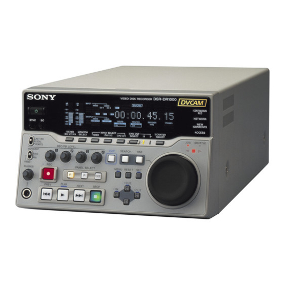
- Page 1 VIDEO DISK RECORDER DSR-DR1000 DSR-DR1000P SERVICE MANUAL 1st Edition...
- Page 2 Ce manual est destiné uniquement aux personnes compétentes en charge de l’entretien. Afin de réduire les risques de décharge électrique, d’incendie ou de blessure n’effectuer que les réparations indiquées dans le mode d’emploi à moins d’être qualifié pour en effectuer d’autres. Pour toute réparation faire appel à une personne compétente uniquement. DSR-DR1000/DR1000P...
- Page 3 équivalent recommandé par le constructeur. Mettre au rebut les batteries usagées conformément aux instructions du fabricant. ADVARSEL! Lithiumbatteri-Eksplosionsfare ved fejlagtig håndtering. Udskiftning må kun ske med batteri af samme fabrikat og type. Levér det brugte batteri tilbage til leverandøren. 1 (P) DSR-DR1000/DR1000P...
- Page 4 For the customers in the Netherlands Voor de klanten in Nederland Hoe u de batterijen moet verwijderen, leest u in de tekst van deze handleiding. Gooi de batterij niet weg maar lever deze in als klein chemisch afval (KCA). 2 (P) DSR-DR1000/DR1000P...
-
Page 5: Table Of Contents
Alarm Display ..................3-1 (E) 3-1-1. Alarm Display when the Main Power is Turned On .... 3-1 (E) 3-2. Error Codes ................... 3-3 (E) 3-2-1. Error Code Descriptions ............3-3 (E) 3-2-2. Display of Previously Detected Error Codes ....... 3-5 (E) 1 (E) DSR-DR1000/DR1000P... - Page 6 CPST (SUPER) Level Adjustment ........6-3 (E) 6-2-3. SYNC Phase Adjustment ............. 6-4 (E) 6-2-4. SC Phase Adjustment ............6-4 (E) 6-3. SDI Free-running Frequency Adjustment ..........6-5 (E) 6-4. HCK Frequency Adjustment ..............6-6 (E) 7. Semiconductor Pin Assignments 2 (E) DSR-DR1000/DR1000P...
- Page 7 RM-195 ....................10-61 PTC-100 ....................10-61 KY-536 ....................10-62 11. Board Layouts DDE-18 ..................... 11-1 DEN-20 ..................... 11-2 DIF-140 ..................... 11-3 HP-115 ...................... 11-3 DPR-224 ....................11-4 DY-19 ......................11-8 KY-536 ...................... 11-9 PTC-100 ....................11-10 RM-195 ....................11-10 3 (E) DSR-DR1000/DR1000P...
-
Page 9: Manual Structure
Manual Structure Purpose of this manual This manual is the Service Manual for the video disk recorder DSR-DR1000/ DR1000P. This manual describes the maintenance information such as service overview, maintenance menu, spare parts, block diagrams, schematic diagrams, and board layouts. -
Page 10: Trademark
Trademark Trademarks and registered trademarks used in this manual are as follows. . Microsoft and Windows are either registered trademarks or trademarks of Mi- crosoft Corporation in the United States and/or other countries. . i.LINK is trademark. 6 (E) DSR-DR1000/DR1000P... -
Page 11: Installation
Section 1 Installation Be sure to install the DSR-DR1000/DR1000P in location satisfying the required operational environment described below to assure the DSR-DR1000/DR1000P superior performance and to maintain the excel- lent serviceability and accessibility. 1-1. Operational Environment . Operating temperature : +5 dC to +40 dC . -
Page 12: Matching Connectors
1-5. Matching Connectors 1-5-1. Matching Connectors/Cables When external cables are connected to the connector on a connector panel during maintenance, the following connectors, cables (or their equivalents) must be used. Connectors on DSR-DR1000/DR1000P Matching connector/cable Panel indication Description Sony Part No. -
Page 13: Input/Output Signals Of The Connectors
BNC x 4 Y/CPST : composite 1.0 Vp-p, 75 Z, negative sync R-Y/S-C : R-Y : 0.7 V p-p (75 % color bars for DSR-DR1000 or 100 % color bars for DSR-DR1000P), 75 Z S-C: 0.286 V p-p (DSR-DR1000) or 0.3 V p-p (DSR-DR1000P), 75 Z (burst level) B-Y/S-Y: B-Y: 0.7 V p-p (75 % color bars for DSR-DR1000 or 100 % color... -
Page 14: Installation Setup
“SYNC PHASE” control on the front panel. (Refer to Chapter 7 of the operating instructions.) . Adjust the SCH of this unit to the system SCH using “SC PHASE” control on the front panel. (Refer to Chapter 7 of the operating instructions.) 1-4 (E) DSR-DR1000/DR1000P... -
Page 15: Service Overview
When an error appears in a HDD . Treat the HDD conform to the above cautions, even when an error appeared. . Keep the HDD in the condition in which the error appeared, and record the details of the error. 2-1 (E) DSR-DR1000/DR1000P... -
Page 16: Location Of Main Parts
Analog video output/Analog audio output/Time code input and output HP-115 board Headphone interface KY-536 board Operation panel PTC-100 board Search dial sensor/Input and output selection DPR-224 board Digital process DIF-140 board Ethernet interface RM-195 board Remote interface 2-2 (E) DSR-DR1000/DR1000P... -
Page 17: Removing/Reattaching Cabinet
Front panel assembly Be careful not to lose the compression spring that is placed in back of the POWER switch on the front panel assembly. 4. Reattach the parts in the reverse order of steps 1 to 3. 2-3 (E) DSR-DR1000/DR1000P... -
Page 18: Function Of Switches On Circuit Board
. When shipping this board as a repair part, the bits of the switch S1601 are set to all OFF. . Before replacing with this board, set the bits 1 and 2 of S1601 according to the unit. 2-4 (E) DSR-DR1000/DR1000P... -
Page 19: Upgrading Software
2-5. Upgrading Software The DSR-DR1000/DR1000P mounts a CPU on the DPR-224 board. The software of this unit can be upgraded by connecting this unit and a personal computer (PC) to the network. Upgrade the software by the following procedures. Preparations 1. -
Page 20: Circuit Protection Parts (Fuse/Ic Link)
PS400 IC LINK 2 A/72 V !1-533-282-21 PS401 PS402 PS403 PS404 DY-19 FUSE (SMD) 0.8 A/125 V !1-576-327-21 IC LINK 0.8 A/72 V !1-576-123-21 DPR-224 PS101 IC LINK 2.5 A/72 V !1-576-398-21 PS102 PS103 PS104 PS105 PS106 2-6 (E) DSR-DR1000/DR1000P... -
Page 21: Replacing Backup Battery
Description : M4T32-BR12SH1 (lithium battery) IC2313, and push the battery until it locks. Sony part number : 1-795-685-11 4. Reattach the HDD (1). (Refer to Section 5-1.) Life : About six years 5. -
Page 22: Disconnecting/Connecting Flexible Card Wire
Connecting Insert the flexible card wire firmly as far as it will go, and push the portions A of the connector. Flexible card wire Insulation side Lock lever Connector Unlocked status Flexible card wire Connector Locked status 2-8 (E) DSR-DR1000/DR1000P... -
Page 23: Error Messages
S1601-1 to 2 on the DPR-224 SETT I NG HAS BEEN board and the contents of non- CHANGED TO volatile memory (EEPROM). DSR-DR1000 NTSC(UC) Operation after detection : None Display : The alarm is displayed until CHECK THE S1601-1~2 SW I TCH ON THE DPR BOARD. - Page 24 SELECT I ONS OF THE SETUP MENU’S FACTORY USE Operation after detection : None I TEMS HAVE BEEN CHANGED. Display : The alarm is displayed until any key is pressed. SET THESE I TEMS TO FACTORY PRESET VALUES. 3-2 (E) DSR-DR1000/DR1000P...
-
Page 25: Error Codes
System control detected abnormality in setup menu data area (IC101/DY-19 board). Detected abnormality in NVRAM (IC2313/DPR-224 board). Detected abnormality in Hours Meter (IC101/DY-19 board). Communication between system control and keyboard was intermitted. (Detected by KY (IC102/DY-19 board).) DSR-DR1000/DR1000P 3-3 (E) - Page 26 Communication error between system control and NSG (IC2901/DPR-224 board) is detected. Communication error between system control and AIF-P (IC1505/DPR-224 board) is detected. Communication error between system control and MPEG DEC (IC1701/DPR-224 board) is detected. Communication error between system control and DEC DSP (IC1202/DPR-224 board) is detected. 3-4 (E) DSR-DR1000/DR1000P...
-
Page 27: Display Of Previously Detected Error Codes
3-2-2. Display of Previously Detected Error Codes When the DSR-DR1000/DR1000P detects an internal abnormality, an error code is memorized in EE- PROM. A maximum of eight error codes detected previously, starting from the latest error code, can be displayed. Displaying the Past Error Codes 1. -
Page 29: Maintenance Menu
The maintenance menu has a layered structure through which you move to perform the various checks, settings and adjustments using the specified menu items. Contents of the maintenance menu are displayed on the video monitor connected to the SUPER connector and the time counter of DSR-DR1000/DR1000P. Values in parenthesis ( ) are time counter display. -
Page 30: Operating The Maintenance Menu
4-2-2. Entering the Maintenance Menu 1. While pressing the [&] key, press the [MENU] key. The DSR-DR1000/DR1000P enters the maintenance menu. The maintenance menu appears on the video monitor. 2. Select the desired item using the [(] key and the [)] key. The cursor shown with a white background moves to the selected item. -
Page 31: Contents Of Maintenance Menu
5. When an item is selected, press the [*] key. The contents of the selected item appear. 6. Press the [&] key to exit MENU DATA CONTROL and return to the main menu. 7. Press the [MENU] key to exit the maintenance menu. DSR-DR1000/DR1000P 4-3 (E) - Page 32 DY-19 board. . When the SET UP MENU is upgraded by ROM’s version upgrade, an alarm message appears after the ROM is replaced. Either initialize the SET UP MENU or execute “LOAD MENU DATA” when the alarm appears. 4-4 (E) DSR-DR1000/DR1000P...
-
Page 33: Disk Check
In the case of trouble : Loading of the data will not start if SET UP MENU data has not been saved or the saved SET UP MENU data contains an error. 4-3-2. Disk Check This menu will be added in future. DSR-DR1000/DR1000P 4-5 (E) -
Page 34: Service Support
(The latest eight maximum errors are displayed.) MAINTENANCE MENU SERVICE SUPPORT ERROR LOG ERROR-92-101 The latest error is displayed on the top. 2. DIAGNOSTICS CONTROL 1 CLEAR ERROR LOG Clears the error history from the ERROR LOG. 4-6 (E) DSR-DR1000/DR1000P... -
Page 35: Others
6. After completing the check, press the [MENU] key to return to the main menu. 7. To check other menus and submenus, repeat steps 4 to 6. 8. Press the [MENU] key to exit the maintenance menu. DSR-DR1000/DR1000P 4-7 (E) - Page 36 : 1. 01 MENU: 1. 0 TO MENU : MENU KEY This example of the display is for DSR-DR1000 (UC). Press the [*] key to display the version below. SOFTWARE VERSION PIE : Version of IC2601 on the DPR-224 board DSR –...
-
Page 37: Replacement Of Main Parts
. The HDD prepared as a service part is formatted at the factory. . Use the following torque driver to tighten the screw. - Torque driver bit (M3): Harnesses Sony part No. J-6323-430-A - Torque driver, shockless (12 kg): Collars Sony part No. J-6530-070-A DPR-224 board Tightening torque: 78.4 x 10... -
Page 38: Ky Frame Assembly And The Components Replacement
CN2201 and CN103 of the DPR-224 board. . Be sure to use the specified fixing screws when 3 x 6 reattaching the HDD bracket to the HDD. HP-115 board KY-536 board PWH3 x 6 KY frame assembly 5-2 (E) DSR-DR1000/DR1000P... -
Page 39: Search Dial Assembly
6. To reattach the search dial assembly, reassemble the Hole A parts in the reverse order of steps 1 to 5. KY frame assembly When reassembling, apply locking compound onto the 3 x 6 Hole A Hole B screw fixing the dial knob. 5-3 (E) DSR-DR1000/DR1000P... -
Page 40: Ky-536/Hp-115 Boards
KY frame. 6. To reattach the board, reassemble the parts in the reverse order of steps 1 to 5. When reassembling, put the projections A and B of the DY-19 board into the grooves of the main chassis. 5-4 (E) DSR-DR1000/DR1000P... -
Page 41: Dde-18/Rm-195 Boards
CN100 Insert the DDE-18 board into the slots of the side 3 x 6 chassis when reattaching the rear panel assembly to the unit. CN101 Slot CN2203 3 x 6 DDE-18 board RM-195 board PWH3 x 6 5-5 (E) DSR-DR1000/DR1000P... -
Page 42: Dpr-224/Den-20/Dif-140 Boards
Be very careful not to fold the flexible card wire. Flexible LW2.6 card wire BVTT2.6 x 6 Flexible card wire DPR-224 board BVTP3 x 8 3 x 6 Harness DPR assembly 3 x 6 Handle CN1003 Switching regulator Connector CN102 DPR-224 board 5-6 (E) DSR-DR1000/DR1000P... -
Page 43: Switching Regulator Replacement
DPR bracket. parts in the reverse order of steps 1 to 4. DPR-224 board DPR bracket BVTP 3 x 8 11. To reattach these boards, reassemble the parts in the reverse order of steps 1 to 10. 5-7 (E) DSR-DR1000/DR1000P... -
Page 45: Electrical Alignment
Equipment Type E1104 Oscilloscope TEKTRONIX TDS460A or equivalent Video signal TEKTRONIX TSG-130A or equivalent E1005 generator (for NTSC) E2201 TP2201 TP2202 TEKTRONIX TSG-131A or equivalent S2001 (for PAL) TP2001 E1001 E1010 Frequency counter ADVANTEST TR5821 or equivalent 6-1 (E) DSR-DR1000/DR1000P... -
Page 46: Video Adjustment
CHROMA PHASE: 80H (Factory shipping state) SETUP LEVEL: 200H (Factory shipping state) Connection Connect the equipment as follows unless otherwise specified. (Connection diagram) DSR-DR1000/DR1000P Oscilloscope VIDEO IN, Y/CPST Video signal generator (NTSC : TSG-130A) REF. VIDEO IN (PAL : TSG-131A) -
Page 47: Y/Cpst Level Adjustment
. AUTO EE SELECT/MENU: EE (Terminated with 75 Z) . INT VIDEO SG/MENU: TRIG: REF. VIDEO 75 % color bars (for NTSC) 100 % color bars (for PAL) . VIDEO OUTPUT/MENU: COMPOSITE Spec.: A = 1.00 ± 0.02 V 6-3 (E) DSR-DR1000/DR1000P... -
Page 48: Sync Phase Adjustment
Input black burst signal . VIDEO OUTPUT/MENU: COMPOSITE . Set the trigger of the waveform at the stable burst portion. . Set the oscilloscope in CHOP mode. 50mV 50mV 100ns Spec.: Overlap both waveforms of A and B. 6-4 (E) DSR-DR1000/DR1000P... -
Page 49: Sdi Free-Running Frequency Adjustment
6-3. SDI Free-running Frequency Adjustment (Connection diagram) DSR-DR1000/DR1000P Oscilloscope Frequency counter DPR-224 (TP) Conditions for adjustment Specification Adjustment Step 1 TP102/DPR-224 (C-13) 1RV101/DPR-224 (B-13) . AUTO EE SELECT/MENU: EE . Short-circuit TP101 (C-13) and E101 (B-13) on the DPR-224 board with a jumper lead. -
Page 50: Hck Frequency Adjustment
6-4. HCK Frequency Adjustment (Connection diagram) DSR-DR1000/DR1000P Frequency counter Oscilloscope VIDEO IN Video signal generator REF. VIDEO IN (NTSC : TSG-130A) No. REF. (PAL : TSG-131A) DPR-224 Board Conditions for adjustment Specification Adjustment Frequency counter TP1301/DPR-224 (D-7) 1RV1302/DPR-224 (C-7) . STOP mode . - Page 51 In addition, for semiconductors with ID Nos., refer to the separate CD-ROM titled “Semiconductor Pin Assignments” (Sony Part No. 9-968-546-xx) that allows searching for parts by semiconductor type or ID No. The semiconductors in the manual or on the CD-ROM are listed by equivalent types.
- Page 52 HY57V161610DTC-7TR ......MB81F161622B-80FN SN75C1168NS(R) ........... SN75C1168NS HY57V561620BT-HDR ............... 7-7 SN75C1168NSR ............SN75C1168NS HY57V641620HGT-H ........TC59S6416BFTL-10 SSM-2142SR ..............SSM-2142S HY57V643220CT-7TR ....... MB811643242A-100FN TC74HC4052AFT(EL) ..........MC74HC4052N IDT49FCT3805PY-TL .......... IDT49FCT805SO TC74VHC04FT(EL) ............. TC74HC04P TC74VHC123AFT(EL) ..........TC74HC123P LM1881M ................LM1881N TC74VHC125FT(EL) ..........MC74HC125N DSR-DR1000/DR1000P...
- Page 53 TC7WT125FU(TE12R) ..........TC7W125FU TLC2932IPWR ............TLC2932IPW TMS320DA150GGU120 ............7-12 TSB43AB22 ................7-13 TSB43AB22APDT ............TSB43AB22 TVP5145PFP ................7-14 UPD61051GD-LML ..............7-15 XC2S150-5FG456C1 ..............7-16 XC2S200-5FG456C1 ..............7-16 OTHERS Page or ID No. 35-18 ................MR021-01 SPI-235-18 ..............MR021-01 TLP814 ................MR010-09 DSR-DR1000/DR1000P...
- Page 54 P VSYNC GENERATOR P BLANK TEST SYNC LUMINANCE DNR, COLOR 2 X OVER CLKIN A CGMS INTER- MODULA- PATTERN INSER- & CHROMA 51 - 55, 58 - 62 GAMMA CONTROL SAMPLING S0 - S9 LEAVE TION GENERATOR TION FILTERS DSR-DR1000/DR1000P...
- Page 55 CXD1934Q (SONY) MPEG AUDIO/VIDEO DECODER –TOP VIEW– INPUTS ACLK : DAC AUDIO SERIAL I/F CLOCK CDBCKI : CD SERIAL BIT CLOCK BYPASS CDEMPI : CD EMPHASIS CDIN1I : CD SERIAL BYPASS CDIN2I : CD S/P DATA INTERFACE BYPASS CDLRKI : CD SERIAL L/R CHANNEL CLOCK BYPASS...
- Page 56 AUDATA0 - AUDATA3 : AUD DATA — AD18 — AUDCK : AUD CLOCK BACK BSREQ — AD17 — GND CPG AUDSYNC : AUD SYNC BREQ BSACK — AD16 XTAL IOIS16 — MD6/ EXTAL PCIFRAME IRDY TRDY — DEVSEL — GNDQ DSR-DR1000/DR1000P...
- Page 57 INPUTS 32-BIT 32-BIT 26-BIT : SHUTDOWN SH BUS SH BUS : ADJUST DATA ADDRESS ADDRESS : INPUT VOLTAGE SUPPLY /DATA OUTPUT : SERIAL COMMUNICATION INTERFACE : OUTPUT VOLTAGE SCIF : SERIAL COMMUNICATION INTERFACE WITH FIFO : TRANSLATION LOOKASIDE BUFFER DSR-DR1000/DR1000P...
- Page 58 OSC32KI DACKJ2 SA10 SA12 DACKJ6 — RSMRSTJ SIDED12 IRQ6 SD12 LA18 SUSTAT1J SIDED3 DREQ7 PIDECS3J IRQ14 ACPWR SIDED11 WDATAJ SD11 PIDECS1J INIT SIDECS1J SIDED4 STEPJ AD26 PIDEA2 A20MJ SIDEA2 DIRJ SIDED7 RTS2J AD25 INTAJMI FERRJ SIDEA0 — HDSELJ SOUT2 DSR-DR1000/DR1000P...
- Page 59 STEPJ : STEP STPCLKJ : STOP CPU INTERNAL CLOCK OUTPUT STROBJ : STROBE OUTPUT SUSTAT1J : SUSPEND STATUS FOR NORTH BRIDGE SYSCLK : ISA SYSTEM CLOCK WDATAJ : WRITE DATA WGATEJ : WRITE GATE : PBSRAM POWER SAVING MODE DSR-DR1000/DR1000P...
- Page 60 T5, R4 INTERFACE MOT0J, MOT1J R5, T4 DRV0J, DRV1J SM BUS SMBCLK STEPJ SMBDATA INTERFACE HDSELJ WDATAJ WGATEJ W6, W4 SOUT1, SOUT2 DSKCHGJ ERRORJ SLCT BUSY STROBJ SLCTINJ Y9, U3 AUTOFDJ, RDATAJ V1, V2, U4 WPROTJ, TRK0J, INDEXJ 7-10 DSR-DR1000/DR1000P...
- Page 61 16-WORD X 2-BIT DRIVER ADDRESS COMMAND SELECTOR DECODER WRITE READ ADDRESS ADDRESS COUNTER COUNTER CONTROL PORT CIRCUIT DRIVER DIGIT CONTROL 40 - 55 GRID COM1 - COM16 DRIVER DUTY CONTROL TIMING TIMING GENERATOR 1 GENERATOR 2 OSC0 OSCILLATOR OSC1 7-11 DSR-DR1000/DR1000P...
- Page 62 CLKMD2 — GND2 IACK — GND2 CLKMD3 HDS1 INT1 HPI16 — READY — BCLKX1 — GND1 BFSX1 S-80928CNNB-G8Y-T2 (SEIKO INSTR) VOLTAGE DETECTOR WITH N-CHANNEL OPEN DRAIN OUTPUT —TOP VIEW— OTHER CD : EXTERNAL CAPACITOR FOR DELAY DELAY CIRCUIT 7-12 DSR-DR1000/DR1000P...
- Page 63 DECODER/RETIMER : PCI SIGNALING CLAMP VOLTAGE POWER XI, XO : CRYSTAL OSCILLATOR CABLE PORT 0 ARBITRATION AND CONTROL STATE MACHINE CABLE LOGIC PORT 1 BIAS VOLTAGE CRYSTAL OSCILLATOR, CURRENT PLL SYSTEM, GENERATOR AND CLOCK GENERATOR TRANSMIT DATA ENCODER 7-13 DSR-DR1000/DR1000P...
- Page 64 67, 69 - 72 D0 - D7 76 - 79 VBI DATA VC0 - VC3 C INTERFACE PROCESSOR PHI INTERFACE INTREQ COPYGUARD GLCO/RTC DETECTION HSYN XTAL1 VSYN SYNC XTAL2 PROCESSOR LINE PALI SCLK PCLK GPCL CHROMA PREF PLLS AVID RSTINB RSTOUTB 7-14 DSR-DR1000/DR1000P...
- Page 65 OVVSYNC — MD31 MD12 GPO6/ — MD13 — IS1/ISERR MD14 OVCLK — — — MD15 OVOUT0/FA14 — — OVOUT1/FA15 RESET OVOUT2/FA16 — — — OVOUT3/FA17 CINT OVOUT4/FA18 — MA10 — OVOUT5/FA19 MA12 CMODE0/CSCLK OVOUT6/FA6 ISSYNC MA13 CMODE1/CSDO OVOUT7/FA7 7-15 DSR-DR1000/DR1000P...
- Page 66 I, GCK1 — — — — I/O (D2) AA22 , I/O AA11 — AB22 — AB11 NOTE NOTE *1 : FOR XC2S150 TYPE *1 : FOR XC2S150 TYPE *2 : FOR XC2S200 TYPE *2 : FOR XC2S200 TYPE 7-16 DSR-DR1000/DR1000P...
-
Page 67: Spare Parts
Therefore, specified parts should be used in the case of replacement. 2. Standardization of Parts Some repair parts supplied by Sony differ from those used for the unit. These are because of parts common- ality and improvement. Parts list has the present standardized repair parts. -
Page 68: Exploded Views
Top panel and HDD 8-2. Exploded Views B3 x 12 B3 x 12 B3 x 12 B3 x 12 PWH3 x 6 B3 x 6 DSR-DR1000/DR1000P... - Page 69 1-824-899-11 s CABLE,IDE 3-628-917-03 o KNOB1 3-704-720-01 s SPRING,COMPRESSION 3-733-690-01 s SCREW +B 4X6(ST) 4-043-045-01 s FOOT(RBR) 4-612-633-01 s SCREW,HD FITTING(STEEL) 7-623-423-07 s WASHER LW 4(TYPE B) 7-682-547-04 s SCREW +B3X6 7-682-550-04 s SCREW +B3X12(EP-FE/CU,NI,CR) 7-682-903-11 s SCREW +PWH 3X6 DSR-DR1000/DR1000P...
- Page 70 Front block PWH3 x 6 PWH3 x 6 PWH3 x 6 PWH2.6 x 6 BTP3 x 10 PWH3 x 6 DSR-DR1000/DR1000P...
- Page 71 Front block Part No SP Description A-8323-665-C s DIAL ASSY, SEARCH 1-477-647-11 s VFD ASSY A-8345-411-A s MOUNTED CIRCUIT BOARD, KY-536 3-704-712-01 s COVER,DIAL 7-682-902-21 s SCREW +PWH 2.6X6 7-682-903-11 s SCREW +PWH 3X6 7-685-547-19 s SCREW +BTP 3X10(EP-FE/ZNBK/CM2) DSR-DR1000/DR1000P...
- Page 72 2.6 x 6 BVTT BVTP 2.6 x 6 3 x 8 3 x 6 3 x 6 PWH3 x 6 3 x 6 3 x 6 BVTP 3 x 8 LW2.6 BVTT 3 x 6 2.6 x 6 3 x 6 DSR-DR1000/DR1000P...
- Page 73 1-468-735-11 s SWITCHING REGULATOR 2-280-622-11 s SUPPORT (M3),HEXAGON 2-280-622-41 s SUPPORT (M3),HEXAGON 7-623-421-07 s WASHER LW 2.6 (TYPE B) 7-623-422-07 s WASHER LW 3 (TYPE 3) 7-682-903-11 s SCREW +PWH 3X6 7-685-646-79 s SCREW +BVTP 3X8 7-685-862-09 s SCREW,+BVTP 2.6X6 (EP-FE/ZNBK/C) DSR-DR1000/DR1000P...
-
Page 74: Electrical Parts List
1-128-694-11 s CAP, CHIP TANTALUM ELECT 22MF C221 1-126-396-11 s CAPACITOR,ELECT 47MF/16V(CHIP) C133 1-107-826-11 s CAPACITOR,CHIP CERAMIC 0.1MF C300 1-126-395-11 s CAPACITOR,ELECT 22MF/16V(CHIP) C134 1-107-826-11 s CAPACITOR,CHIP CERAMIC 0.1MF C301 1-126-395-11 s CAPACITOR,ELECT 22MF/16V(CHIP) C135 1-162-915-11 s CAPACITOR,CERAMIC 10PF/50V CH C302 1-126-395-11 s CAPACITOR,ELECT 22MF/16V(CHIP) DSR-DR1000/DR1000P... - Page 75 1-211-991-11 s RESISTOR,CHIP 82 1/10W (1608) 8-759-180-19 s IC NJU7211U50-TE1 R112 1-211-991-11 s RESISTOR,CHIP 82 1/10W (1608) 8-759-442-54 s IC RH5RL50AA-T1 R113 1-218-839-11 s RESISTOR,CHIP 470 1/10W (1608) 8-759-180-19 s IC NJU7211U50-TE1 R114 1-218-839-11 s RESISTOR,CHIP 470 1/10W (1608) DSR-DR1000/DR1000P...
- Page 76 1-218-867-11 s RESISTOR,CHIP 6.8K 1/10W(1608) R339 1-218-887-11 s RESISTOR,CHIP 47K 1/10W (1608) R219 1-218-867-11 s RESISTOR,CHIP 6.8K 1/10W(1608) R340 1-218-887-11 s RESISTOR,CHIP 47K 1/10W (1608) R220 1-218-834-11 s RESISTOR,CHIP 300 1/10W (1608) R341 1-218-823-11 s RESISTOR,CHIP 100 1/10W (1608) 8-10 DSR-DR1000/DR1000P...
- Page 77 1-107-826-11 s CAPACITOR,CHIP CERAMIC 0.1MF C147 1-162-908-11 s CAPACITOR,CERAMIC 3PF/50V 1608 C148 1-107-826-11 s CAPACITOR,CHIP CERAMIC 0.1MF C149 1-164-173-11 s CAPACITOR,CERAMIC 3900PF/50V B C150 1-164-173-11 s CAPACITOR,CERAMIC 3900PF/50V B C151 1-107-826-11 s CAPACITOR,CHIP CERAMIC 0.1MF C152 1-107-826-11 s CAPACITOR,CHIP CERAMIC 0.1MF 8-11 DSR-DR1000/DR1000P...
- Page 78 1-162-923-11 s CAPACITOR,CERAMIC 47PF/50V CH C310 1-162-923-11 s CAPACITOR,CERAMIC 47PF/50V CH D300 8-719-801-78 s DIODE 1SS184 C311 1-162-923-11 s CAPACITOR,CERAMIC 47PF/50V CH D301 8-719-820-41 s DIODE 1SS302 C312 1-162-923-11 s CAPACITOR,CERAMIC 47PF/50V CH D302 8-719-820-41 s DIODE 1SS302 8-12 DSR-DR1000/DR1000P...
- Page 79 1-218-837-11 s RESISTOR,CHIP 390 1/10W (1608) IC406 8-759-338-95 s IC NJM2903V (TE2) R132 1-218-871-11 s RESISTOR,CHIP 10K 1/10W (1608) R133 1-218-837-11 s RESISTOR,CHIP 390 1/10W (1608) IC407 8-759-533-85 s IC L88M05T-FA-TL R134 1-218-837-11 s RESISTOR,CHIP 390 1/10W (1608) IC408 8-759-180-19 s IC NJU7211U50-TE1 8-13 DSR-DR1000/DR1000P...
- Page 80 1-218-881-11 s RESISTOR, CHIP 27K 1/10W(1608) R331 1-216-803-11 s RESISTOR,CHIP 33 1/16W (1608) R218 1-218-881-11 s RESISTOR, CHIP 27K 1/10W(1608) R332 1-216-803-11 s RESISTOR,CHIP 33 1/16W (1608) R219 1-218-881-11 s RESISTOR, CHIP 27K 1/10W(1608) R333 1-216-803-11 s RESISTOR,CHIP 33 1/16W (1608) 8-14 DSR-DR1000/DR1000P...
- Page 81 1-233-574-11 s RESISTOR,CHIP NETWORK 10 1-233-574-11 s RESISTOR,CHIP NETWORK 10 1-233-574-11 s RESISTOR,CHIP NETWORK 10 RB10 1-233-574-11 s RESISTOR,CHIP NETWORK 10 RB11 1-233-574-11 s RESISTOR,CHIP NETWORK 10 RB12 1-233-574-11 s RESISTOR,CHIP NETWORK 10 TP101 1-535-757-11 s CHIP, CHECKER (CONNECTOR) 8-15 DSR-DR1000/DR1000P...
- Page 82 1-107-826-11 s CAPACITOR,CHIP CERAMIC 0.1MF C207 1-107-826-11 s CAPACITOR,CHIP CERAMIC 0.1MF C208 1-107-826-11 s CAPACITOR,CHIP CERAMIC 0.1MF C209 1-107-826-11 s CAPACITOR,CHIP CERAMIC 0.1MF C210 1-107-826-11 s CAPACITOR,CHIP CERAMIC 0.1MF C301 1-107-826-11 s CAPACITOR,CHIP CERAMIC 0.1MF C302 1-107-826-11 s CAPACITOR,CHIP CERAMIC 0.1MF 8-16 DSR-DR1000/DR1000P...
- Page 83 1-107-826-11 s CAPACITOR,CHIP CERAMIC 0.1MF C521 1-107-826-11 s CAPACITOR,CHIP CERAMIC 0.1MF C921 1-107-826-11 s CAPACITOR,CHIP CERAMIC 0.1MF C522 1-107-826-11 s CAPACITOR,CHIP CERAMIC 0.1MF C922 1-107-826-11 s CAPACITOR,CHIP CERAMIC 0.1MF C523 1-137-703-91 s CAPACITOR, TANTALUM 1MF(3216) C923 1-107-826-11 s CAPACITOR,CHIP CERAMIC 0.1MF 8-17 DSR-DR1000/DR1000P...
- Page 84 1-107-826-11 s CAPACITOR,CHIP CERAMIC 0.1MF C1117 1-107-826-11 s CAPACITOR,CHIP CERAMIC 0.1MF C1344 1-107-826-11 s CAPACITOR,CHIP CERAMIC 0.1MF C1118 1-107-826-11 s CAPACITOR,CHIP CERAMIC 0.1MF C1345 1-107-826-11 s CAPACITOR,CHIP CERAMIC 0.1MF C1119 1-107-826-11 s CAPACITOR,CHIP CERAMIC 0.1MF C1346 1-107-826-11 s CAPACITOR,CHIP CERAMIC 0.1MF 8-18 DSR-DR1000/DR1000P...
- Page 85 1-107-826-11 s CAPACITOR,CHIP CERAMIC 0.1MF C1418 1-107-826-11 s CAPACITOR,CHIP CERAMIC 0.1MF C1479 1-107-826-11 s CAPACITOR,CHIP CERAMIC 0.1MF C1419 1-107-826-11 s CAPACITOR,CHIP CERAMIC 0.1MF C1481 1-107-826-11 s CAPACITOR,CHIP CERAMIC 0.1MF C1420 1-107-826-11 s CAPACITOR,CHIP CERAMIC 0.1MF C1482 1-107-826-11 s CAPACITOR,CHIP CERAMIC 0.1MF 8-19 DSR-DR1000/DR1000P...
- Page 86 1-107-826-11 s CAPACITOR,CHIP CERAMIC 0.1MF C1707 1-107-826-11 s CAPACITOR,CHIP CERAMIC 0.1MF C1921 1-137-740-91 s CAP, TANTALUM ELECT 47MF(3528) C1708 1-107-826-11 s CAPACITOR,CHIP CERAMIC 0.1MF C1922 1-107-826-11 s CAPACITOR,CHIP CERAMIC 0.1MF C1709 1-107-826-11 s CAPACITOR,CHIP CERAMIC 0.1MF C1923 1-107-826-11 s CAPACITOR,CHIP CERAMIC 0.1MF 8-20 DSR-DR1000/DR1000P...
- Page 87 1-137-739-11 s CAPACITOR, TANTALUM ELECT C2203 1-107-826-11 s CAPACITOR,CHIP CERAMIC 0.1MF C2406 1-137-739-11 s CAPACITOR, TANTALUM ELECT C2204 1-107-826-11 s CAPACITOR,CHIP CERAMIC 0.1MF C2407 1-107-826-11 s CAPACITOR,CHIP CERAMIC 0.1MF C2205 1-162-915-11 s CAPACITOR,CERAMIC 10PF/50V CH C2408 1-107-826-11 s CAPACITOR,CHIP CERAMIC 0.1MF 8-21 DSR-DR1000/DR1000P...
- Page 88 1-107-826-11 s CAPACITOR,CHIP CERAMIC 0.1MF C2711 1-107-826-11 s CAPACITOR,CHIP CERAMIC 0.1MF C2926 1-107-826-11 s CAPACITOR,CHIP CERAMIC 0.1MF C2712 1-107-826-11 s CAPACITOR,CHIP CERAMIC 0.1MF C2927 1-125-837-11 s CAPACITOR,CHIP CERAMIC1MF/6.3V C2713 1-107-826-11 s CAPACITOR,CHIP CERAMIC 0.1MF C2928 1-125-837-11 s CAPACITOR,CHIP CERAMIC1MF/6.3V 8-22 DSR-DR1000/DR1000P...
- Page 89 1-794-817-11 o CONNECTOR, COAXIAL (BNC TYPE) FB104 1-469-094-11 s FERRITE, EMI (SMD) 1-774-966-11 o CONNECTOR, BNC (RECEPTACLE) FB105 1-469-094-11 s FERRITE, EMI (SMD) 1-766-431-21 o HOUSING, CONNECTOR 30P 1-785-921-11 s JACK (DIA. 3.5), SMALL FB106 1-469-094-11 s FERRITE, EMI (SMD) 8-23 DSR-DR1000/DR1000P...
- Page 90 8-759-490-41 s IC TC74VHCT541AFT(EL) IC1406 8-759-647-49 s IC AL422B-TEL IC910 8-759-490-41 s IC TC74VHCT541AFT(EL) IC1407 8-759-386-25 s IC 74LCX245MTCX IC911 8-759-490-41 s IC TC74VHCT541AFT(EL) IC1408 6-702-238-11 s IC HY57V643220CT-7TR IC912 8-759-490-41 s IC TC74VHCT541AFT(EL) IC1409 8-759-647-49 s IC AL422B-TEL 8-24 DSR-DR1000/DR1000P...
- Page 91 6-701-543-01 s IC SN75C1168NS L903 1-412-939-11 s INDUCTOR 1.0UH (2520) IC2209 8-759-435-08 s IC MAX314CSE-TE2 L904 1-412-939-11 s INDUCTOR 1.0UH (2520) IC2210 8-759-524-04 s IC TC74VHC125FT (EL) IC2301 8-759-495-92 s IC SN74LVTH16245ADGGR L905 1-412-939-11 s INDUCTOR 1.0UH (2520) 8-25 DSR-DR1000/DR1000P...
- Page 92 1-576-398-21 s RINK, IC (CCP2E63) R122 1-216-801-11 s RESISTOR,CHIP 22 1/10W (1608) PS104 1-576-398-21 s RINK, IC (CCP2E63) R123 1-216-805-11 s RESISTOR,CHIP 47 1/10W 1608 PS105 1-576-398-21 s RINK, IC (CCP2E63) R124 1-216-805-11 s RESISTOR,CHIP 47 1/10W 1608 8-26 DSR-DR1000/DR1000P...
- Page 93 1-211-990-11 s RESISTOR,CHIP 75 1/10W (1608) R1010 1-218-880-11 s RESISTOR,CHIP 24K 1/10W (1608) R507 1-218-845-11 s RESISTOR,CHIP 820 1/10W (1608) R1011 1-216-841-11 s RESISTOR, CHIP 47K 1/10W 1608 R508 1-218-845-11 s RESISTOR,CHIP 820 1/10W (1608) R1012 1-216-841-11 s RESISTOR, CHIP 47K 1/10W 1608 8-27 DSR-DR1000/DR1000P...
- Page 94 1-216-864-11 s CONDUCTOR, CHIP (1608) R1325 1-216-801-11 s RESISTOR,CHIP 22 1/10W (1608) R1169 1-216-864-11 s CONDUCTOR, CHIP (1608) R1326 1-216-801-11 s RESISTOR,CHIP 22 1/10W (1608) R1170 1-216-864-11 s CONDUCTOR, CHIP (1608) R1327 1-216-797-11 s RESISTOR,CHIP 10 1/10W 1608 8-28 DSR-DR1000/DR1000P...
- Page 95 1-216-864-11 s CONDUCTOR, CHIP (1608) R1455 1-216-864-11 s CONDUCTOR, CHIP (1608) R1389 1-216-801-11 s RESISTOR,CHIP 22 1/10W (1608) R1456 1-216-864-11 s CONDUCTOR, CHIP (1608) R1390 1-216-841-11 s RESISTOR, CHIP 47K 1/10W 1608 R1457 1-216-801-11 s RESISTOR,CHIP 22 1/10W (1608) 8-29 DSR-DR1000/DR1000P...
- Page 96 1-216-841-11 s RESISTOR, CHIP 47K 1/10W 1608 R2058 1-216-801-11 s RESISTOR,CHIP 22 1/10W (1608) R1907 1-216-841-11 s RESISTOR, CHIP 47K 1/10W 1608 R2059 1-216-833-11 s RESISTOR,CHIP 10K 1/10W (1608) R1908 1-216-841-11 s RESISTOR, CHIP 47K 1/10W 1608 R2060 1-216-833-11 s RESISTOR,CHIP 10K 1/10W (1608) 8-30 DSR-DR1000/DR1000P...
- Page 97 1-216-833-11 s RESISTOR,CHIP 10K 1/10W (1608) R2312 1-216-864-11 s CONDUCTOR, CHIP (1608) R2240 1-216-833-11 s RESISTOR,CHIP 10K 1/10W (1608) R2313 1-216-833-11 s RESISTOR,CHIP 10K 1/10W (1608) R2241 1-216-833-11 s RESISTOR,CHIP 10K 1/10W (1608) R2314 1-216-833-11 s RESISTOR,CHIP 10K 1/10W (1608) 8-31 DSR-DR1000/DR1000P...
- Page 98 1-216-864-11 s CONDUCTOR, CHIP (1608) R2967 1-216-845-11 s RESISTOR,CHIP 100K 1/10W(1608) R2802 1-216-841-11 s RESISTOR, CHIP 47K 1/10W 1608 R2968 1-216-801-11 s RESISTOR,CHIP 22 1/10W (1608) R2803 1-216-864-11 s CONDUCTOR, CHIP (1608) R2969 1-216-801-11 s RESISTOR,CHIP 22 1/10W (1608) 8-32 DSR-DR1000/DR1000P...
- Page 99 1-239-711-11 s NETWORK, RESISTOR 0 (1608) RB1106 1-239-711-11 s NETWORK, RESISTOR 0 (1608) S1601 1-692-271-31 s SWITCH, SLIDE S2001 1-572-473-11 s SWITCH, TACTIL RB1108 1-239-711-11 s NETWORK, RESISTOR 0 (1608) S2301 1-692-271-31 s SWITCH, SLIDE RB1109 1-239-711-11 s NETWORK, RESISTOR 0 (1608) 8-33 DSR-DR1000/DR1000P...
- Page 100 8-729-928-54 s TRANSISTOR DTA123JE Q103 8-729-928-54 s TRANSISTOR DTA123JE Q104 8-729-928-54 s TRANSISTOR DTA123JE Q105 8-729-928-54 s TRANSISTOR DTA123JE Q106 8-729-928-54 s TRANSISTOR DTA123JE Q107 8-729-928-54 s TRANSISTOR DTA123JE Q201 8-729-929-08 s TRANSISTOR DTC123JE Q202 8-729-929-08 s TRANSISTOR DTC123JE 8-34 DSR-DR1000/DR1000P...
- Page 101 1-218-827-11 s RESISTOR,CHIP 150 1/10W (1608) R229 1-216-813-11 s RESISTOR, CHIP 220 1/10W 1608 R230 1-218-827-11 s RESISTOR,CHIP 150 1/10W (1608) R231 1-216-813-11 s RESISTOR, CHIP 220 1/10W 1608 R232 1-218-827-11 s RESISTOR,CHIP 150 1/10W (1608) R233 1-216-821-11 s RESISTOR,CHIP 1.0K 1/10W(1608) 8-35 DSR-DR1000/DR1000P...
- Page 102 CN2203 1-750-249-21 o CONNECTOR, FPC 16P C206 1-117-713-21 s CAP, CHIP TYPE ELECT 100MF C208 1-162-923-11 s CAPACITOR,CERAMIC 47PF/50V CH C209 1-162-967-11 s CAPACITOR,CERAMIC 3300PF/50V B C300 1-162-927-11 s CAPACITOR,CERAMIC 100PF/50V CH C301 1-162-927-11 s CAPACITOR,CERAMIC 100PF/50V CH 8-36 DSR-DR1000/DR1000P...
- Page 103 (TE12R) 1-216-821-11 s RESISTOR,CHIP 1.0K 1/10W(1608) IC104 8-759-524-04 s IC TC74VHC125FT (EL) 1-216-864-11 s CONDUCTOR, CHIP (1608) 1-216-864-11 s CONDUCTOR, CHIP (1608) IC105 8-759-196-97 s IC TC7SH32FU (TE85R) 1-216-864-11 s CONDUCTOR, CHIP (1608) IC106 8-759-490-41 s IC TC74VHCT541AFT(EL) 8-37 DSR-DR1000/DR1000P...
- Page 104 1-216-841-11 s RESISTOR, CHIP 47K 1/10W 1608 R307 1-216-809-11 s RESISTOR,CHIP 100 1/10W 1608 R157 1-216-853-11 s RESISTOR,CHIP 470K 1/16W(1608) R308 1-216-809-11 s RESISTOR,CHIP 100 1/10W 1608 R158 1-216-841-11 s RESISTOR, CHIP 47K 1/10W 1608 R309 1-216-809-11 s RESISTOR,CHIP 100 1/10W 1608 8-38 DSR-DR1000/DR1000P...
-
Page 105: Frame List
RB401 1-233-412-11 s RESISTOR,CHIP NETWORK 1K RB402 1-236-908-11 s RESISTOR,NETWORK 10K (3216) RV101 1-241-856-11 s RESISTOR, VAR, CARBON 5K RV102 1-241-856-11 s RESISTOR, VAR, CARBON 5K 1-554-118-00 s SWITCH,PUSH 1-439-573-11 s TRANSFORMER, CONVERTER X101 1-767-636-11 s VIBRATOR, CRYSTAL 8-39 DSR-DR1000/DR1000P... -
Page 106: Packing Materials & Supplied Accessories
8-5. Packing Materials & Supplied Accessories ------------------ DSR-DR1000 (for J) ------------------ Ref. No. or Q'ty Part No. SP Description 1-477-401-11 s REMOTE COMMANDER (RM-LG2) 1-791-041-31 s CORD SET, POWER 1-793-461-11 o PLUG, CONVERSION (3P-2P) 3-704-782-01 s OPERATING INSTRUCTIONS ------------------- DSR-DR1000 (for UC) ------------------- Ref. -
Page 107: Circuit Description And Block Diagram
Circuit Description Recording System 1. Video Signal Processing System For DSR-DR1000/DR1000P, the input analog audio signal is converted into the serial digital signal at IC308 on the DDE-18 board, and is then sent to the DPR-224 board. Recording System The SDI and AES/EBU signals are sent to IC801 on the DPR-224 board to decode into the serial digital For DSR-DR1000/DR1000P, the input analog video signal is converted into the component parallel signals. - Page 108 IC919 PBDT12 PBSRCDT12 IC1505 DEN-20 FPGA IC405 EEPBDT34 PBDSP12 METER PB_VR/MUTE FIFO HN004 IC920 IC2917 MPAU1_34 HARNESS PBSRCDT34 PBDT34 AIF_P CN2(4P) (DPR-HP) CN1003(4P) PBDSP34 HEAD_PHONE DSP_MONIOUT HP_L_OUT HP_L_OUT MONI_VR AU_DSP HP_R_OUT HP_R_OUT IC926 IC1905 i.LINK12_IN IC927 AIF_Q i.LINK34_IN HP-115 DSR-DR1000/DR1000P...
-
Page 109: Overall
9,21 9,21 REG+6.2V REMOTE OUT POWER 9PIN_OUT_TX- 9PIN_OUT_TX- RM_OUT_TX- POWER_OUT PW_ON PW_ON SWITCH 9PIN_OUT_TX+ 9PIN_OUT_TX+ RM_OUT_RX+ PRIORITY_OUT PRIORITY_OUT REG-12V REG-12V -12V 9PIN_OUT_RX+ 9PIN_OUT_RX+ RM_PRIORITY_OUT 9PIN_OUT_RX- 9PIN_OUT_RX- RM_OUT_TX+ RM_OUT_RX- REG-6.2V 11,23 11,23 REG-6.2V -6.2V EVER3.3V EVER3.3V RM-195 SWITCHING REGULATOR Overall DSR-DR1000/DR1000P... - Page 111 AFE_GND NSUB DVDD2 AFE_VDD +3.3V L106 PLL_AVDD 10uH C165 PLL_AGND 0.1uF C163 22uF TA-C CL110 CL112 CL113 CL115 CL114 CL111 DDE-18 (1/3) R169 BOARD NO. 1-686-167-11 +3.3V-D DDE-18: For except Japan DDE-18A: For Japan X101 DSR-DR1000_DDE-18_011_1 14.31818MHz 10-1 10-1 DSR-DR1000/DR1000P...
- Page 112 +12V-3 RN-C 470pF R223 +12V-3 DDE-18 (2/3) 470pF R219 C211 R231 L203 6.8k RN-C 10uF 8.2uH RN-C RN-C -12V-3 BOARD NO. 1-686-167-11 CH2_A/D_Y DDE-18: For except Japan R237 3.3k DDE-18A: For Japan RN-C DSR-DR1000_DDE-18_011_2 C219 -12V-3 47pF 10-2 10-2 DSR-DR1000/DR1000P...
- Page 113 TST3 -5V-3 C322 R344 SMODE2 TST4 10uF RN-C R308 C305 R312 IC308 4.7k 47pF IC307 (1/2) AK5352-VF-E2 RN-C RN-C NJM4580V(TE2) D300 D301 1SS300-TE85L 1SS300-TE85L DDE-18 (3/3) BOARD NO. 1-686-167-11 DDE-18: For except Japan DDE-18A: For Japan DSR-DR1000_DDE-18_011_3 10-3 10-3 DSR-DR1000/DR1000P...
- Page 114 RESET 0.0039uF SRCK RN-C SRCLR H;NTSC H;S_VIDEO R117 R105 RN-C R107 CN201 (12/30) Enc2_Data1 VIDEO_ENC2_DT1 Enc2_Data0 CN201 (13/30) DEN-20 (1/4) VIDEO_ENC2_DT0 LRCK R113 BOARD NO. 1-686-168-12 R114 SCRESET DDE-20: For except Japan CK27 DDE-20A: For Japan DSR-DR1000_DEN-20_012_1 10-4 10-4 DSR-DR1000/DR1000P...
- Page 115 AVSS C207 RN-C 0.1uF C225 100pF IC202 AK4324-VF-E2 +3.3V IC403 (6/7) IC403 (5/7) R201 TC74VHCT04AFT(EL) TC74VHCT04AFT(EL) 100k DEN-20 (2/4) RN-C CN201 (14/30) L;ENC_RESET BOARD NO. 1-686-168-12 DDE-20: For except Japan L;RESET H;RESET DDE-20A: For Japan DSR-DR1000_DEN-20_012_2 MONITER_MUTE 10-5 10-5 DSR-DR1000/DR1000P...
- Page 116 RN-C R337 Q303 2SC4213B-TE85L RN-C R332 -12V-2 Q308 -5V-3 R321 2SC4213B-TE85L 3.9k RN-C Q310 2SC4213B-TE85L R333 Q306 2SB624T1-BV345 MUTE6 MONITER_MUTE R329 C313 RN-C 47uF DEN-20 (3/4) BOARD NO. 1-686-168-12 DDE-20: For except Japan DDE-20A: For Japan DSR-DR1000_DEN-20_012_3 10-6 10-6 DSR-DR1000/DR1000P...
- Page 117 R412 8.2k RN-C R410 R415 FL401 C401 3.3k R425 DEN-20 (4/4) 220uF 2.7k CN1 (2/2) RN-C RN-C GND2 GND1 IC405(1/2) C429 BOARD NO. 1-686-168-12 R401 NJM4556AV(TE2) 0.1uF DDE-20: For except Japan IC405(2/2) NJM4556AV(TE2) DDE-20A: For Japan DSR-DR1000_DEN-20_012_4 10-7 10-7 DSR-DR1000/DR1000P...
- Page 118 PCI_FRAME RB11 PCI_C/BE3 PCI_C/BE3 PCI_C/BE2 PCI_C/BE2 PCI_C/BE0 PCI_C/BE0 PCI_C/BE1 PCI_C/BE1 PCI_GNT2 PCI_GNT2 RB12 PCI_REQ2 PCI_REQ2 PCI_DEVSEL PCI_DEVSEL PCI_TRDY PCI_TRDY PCI_CLK2 PCI_CLK2 CL10 +3.3V REG+3.3V REG+3.3V REG+3.3V REG+3.3V REG+3.3V 47uF 0.1uF 6.3V DIF-140 (1/2) BOARD NO. 1-686-169-12 DSR-DR1000_DIF-140_012_1 10-8 10-8 DSR-DR1000/DR1000P...
- Page 119 PME#[A6] C/BE2#[F3] PCI_C/BE2 PCI_AD25 PCI_AD17 AD25[A5] AD17[E3] R107 100k R112 4.7k X101 C103 25MHz 0.1uF C101 C102 PCI_REQ2 22pF 22pF R108 PCI_SERR PCI_RST PCI_INTB PCI_PERR PCI_FRAME R109 R111 R110 RN-C PCI_AD DIF-140 (2/2) BOARD NO. 1-686-169-12 DSR-DR1000_DIF-140_012_2 10-9 10-9 DSR-DR1000/DR1000P...
- Page 120 REG+3.3V C135 220uF RV101;DEC FREQ REG+6.2V CCP2E63 2.5A KOA PS105 REG-6.2V EVER3.3V EVER3.3V C128 C126 220uF +12V CN103 -6.2V 0.1uF HDD +12V E101 +5V-REG HDD +5.1V C129 47uF DPR-224 (1/29) 6.3V C127 0.1uF BOARD NO. 1-686-170-12 DSR-DR1000_DPR-224_012_1 10-10 10-10 DSR-DR1000/DR1000P...
- Page 121 SDIRDTO1 INDT0 SDIRDTO0 RB207 L_SDI_IN +3.3V IC208 C210 0.1uF TC74VHC541FT(EL) RB208 INDT9 SDIRDTO9 INDT8 SDIRDTO8 SDIR_PCERD PCERD_IN IN_CK27 001,008 SDIRCK27 SDIRF IN_FD IN_VD SDIRV IN_HD SDIRH CL202 RB209 R203 DPR-224 (2/29) 001,008 SDIR_BUS BOARD NO. 1-686-170-12 DSR-DR1000_DPR-224_012_2 10-11 10-11 DSR-DR1000/DR1000P...
- Page 122 RB304 V_OUT_DT6 SDIPDTI6 SIVD1 V_OUT_DT7 SDIPDTI7 CK27 SIVD0 V_OUT_DT8 SDIPDTI8 V_OUT_DT9 SDIPDTI9 RB305 EXTF NSG_OFOE EXTH NSG_FH SDIPCK27 013,029 NSG_CK27D R310 R309 C303 R307 0.1uF R308 NCG_FRAME to FPGA NCG_CHARA NCG_RESET DPR-224 (3/29) BOARD NO. 1-686-170-12 DSR-DR1000_DPR-224_012_3 10-12 10-12 DSR-DR1000/DR1000P...
- Page 123 C418 10uF RN-C DTA144EE-TL C414 TA-C 10pF C416 0.1uF C411 R413 0.1uF C413 C420 0.1uF 0.1uF BCAP C401 SCKX 10uF R410 R418 SCKY TA-C RN-C Q403 DTC144EE-TL RV501; ENC FREQ P/S_RESET DPR-224 (4/29) BOARD NO. 1-686-170-12 DSR-DR1000_DPR-224_012_4 10-13 10-13 DSR-DR1000/DR1000P...
- Page 124 FL504 R502 R526 C510 C517 1.1k L506 RN-C (2/4) 4.7uH 2012 2012 RN-C AES OUT 1/2 AES_OUT_12 GND1 GND2 R508 R518 C502 C508 C518 RN-C 68pF RN-C 0.1uF R524 GNDGND RN-C DPR-224 (5/29) BOARD NO. 1-686-170-12 DSR-DR1000_DPR-224_012_5 10-14 10-14 DSR-DR1000/DR1000P...
- Page 125 PFDINH IC603 LGND VCOGND TC74VHC367FT(EL) C607 C608 C611 0.1uF 0.1uF 0.1uF +3.3V C602 0.1uF RB602 AESRDT34 AES_IN_DT3/4 AESRLRCK34 AESPLL1B AES_IN_LRCK3/4 AESRBCK34 AES_IN_BCK3/4 AESR256FS34 AESPLL1A AES_IN_256FS3/4 IC606 AES_IN_34 AESDTI1 TC7WT125FU(TE12R) AES_IN_12 AESDTI0 DPR-224 (6/29) BOARD NO. 1-686-170-12 DSR-DR1000_DPR-224_012_6 10-15 10-15 DSR-DR1000/DR1000P...
- Page 127 C701 470pF +3.3V R701 4.7k RN-C Q701 001,013,014,015,019,023,029 DTC144EE-TL Q703 JC_RESET DTC144EE-TL DIF_BUS +3.3V RSCOM R704 013,014,019,026,027,029 RB701 RSSO SYSO RSSI SYSI RSCK DIF_CS DIFRCS SYCK +3.3V C702 0.1uF IC701 TC7WH125FU(TE12R) DPR-224 (7/29) BOARD NO. 1-686-170-12 DSR-DR1000_DPR-224_012_7 10-17 10-17 DSR-DR1000/DR1000P...
- Page 128 IO65[A3] IO151[Y18] SDIRDTO8 IO66/VREF9[D2] IO150[Y17] SDIRDTO7 256FSO IO67/VREF10[E2] IO149[Y16] SDIRDTO6 256FSI IO145[Y12] IO68[F2] IO148[Y15] SDIRDTO5 IO144/VREF23[Y10] IO69[H2] IO147[Y14] SDIPCK27O SDIRDTO4 SDIPDTO9 IO143[Y9] IO70[J2] IO146[Y13] SDIRDTO3 SDIPDTO8 IO72/VREF11[N2] SDIRDTO2 SDIPDTO7 IO73[P2] SDIRDTO1 SDIPDTO6 IO74[R2] SDIP_BUS 003,004 001,002 SDIR_BUS 10-18 10-18 DSR-DR1000/DR1000P...
- Page 129 VCCO22[J17] IO86[AA10] VCCO21[K17] NC16[AA11] IO280[M17] NC17[AA16] VCCO20[N17] GND7[AA21] VCCO19[P17] NC18[M21] VCCO18[R17] IO106[H21] VCCO17[T17] GND8[B21] VCCINT7[U17] TDI[B20] VCCO16[U16] NC19[B16] VCCO15[U15] NC20[B11] VCCO14[U14] GND9[C3] VCCO13[U13] TMS[D3] VCCO12[U10] NC21[R3] VCCO11[U9] 001,002 SDIRCK27 DPR-224 (8/29) BOARD NO. 1-686-170-12 DSR-DR1000_DPR-224_012_8 PLD_CFG 020,023,026,027,028,029 10-19 10-19 DSR-DR1000/DR1000P...
- Page 130 L_AESR34 TC7SH04FU-TE85R SLAVE +3.3V INIT QSRC34_SLAVE H_2CH QSRC34_MUTE QSRC34_DEMP DR256FS34 FI128 FIS1 C908 0.1uF IC912 FIS0 TC74VHCT541AFT(EL) MUTE SRC12_SLAVE PASS QSRC34_DEMP SRC12_MUTE R909 DEMP SRC12_DEMP TEST3 TEST R907 SRC34_FS1 TEST2 4.7k SRC34_FS2 TEST1 RN-C SRC34_SLAVE SRC34_MUTE SRC34_DEMP 10-20 10-20 DSR-DR1000/DR1000P...
- Page 131 26 TEST3 36 DEMP 19 FIS0 TEST 25 TEST2 26 TEST3 TEST 24 TEST1 25 TEST2 35 MUTE 24 TEST1 18 PASS R914 36 DEMP 26 TEST3 TEST 25 TEST2 24 TEST1 DPR-224 (9/29) BOARD NO. 1-686-170-12 DSR-DR1000_DPR-224_012_9 10-21 10-21 DSR-DR1000/DR1000P...
- Page 133 RESET1 D1004 1SS301-TE85L R1041 Q1002 R1046 DTC144EE-TL Q1013 2SA1611T1-M5M6 C1040 C1043 4.7uF R1047 100uF RN-C D1003 D1005 DA204UT106 DA204UT106 R1004 RN-C E1001 E1002 E1003 E1004 E1005 E1006 E1007 E1008 E1009 E1010 DPR-224 (10/29) BOARD NO. 1-686-170-12 DSR-DR1000_DPR-224_012_10 10-23 10-23 DSR-DR1000/DR1000P...
- Page 134 TMS[G12] TRST A17[B13] TRST[H12] RB1103 (2/4) RB1104 (3/4) R1123 4.7k DSPENC_RST 011,023 RB1105 RB1105 R1128 R1134 R1144 4.7k (1/4) (2/4) E1104 RB1106 RB1106 R1143 (1/4) (2/4) DSPENC1CS DSPE_INT 009,018,027,029 SEL_REC_AU 016,018 E_A0-5 016,018,029 E_D0-7 016,018 E_WE0 DSPENC1INT 10-24 10-24 DSR-DR1000/DR1000P...
- Page 135 TMS1 RB1109 (1/4) D5[C13] TMS[G12] TRST A17[B13] TRST[H12] R1163 4.7k DSPENC_RST 011,023 R1183 R1168 R1174 4.7k R1178 RB1110 RB1110 RB1111 C1119 0.1uF (1/4) (2/4) (1/4) RB1111 (2/4) R1184 DSPENC2CS DSP_JTAG_BUS DSPENC2INT DPR-224 (11/29) BOARD NO. 1-686-170-12 DSR-DR1000_DPR-224_012_11 10-25 10-25 DSR-DR1000/DR1000P...
- Page 137 DSP3_30MCK X2/CLKIN[E13] RS[E12] DSPDEC_RST CL1202 D2[D13] CLKOUT[F12] CL1213 TMS1 CL1203 D5[C13] TMS[G12] TRST A17[B13] TRST[H12] E1209 C1208 R1223 0.1uF R1227 R1233 4.7k 016,017 C_WE0 DSPDEC1CS 016,017 C_A0-21 016,017 C_D0-15 DPR-224 (12/29) DSP_JTAG_BUS BOARD NO. 1-686-170-12 DSR-DR1000_DPR-224_012_12 DSPDEC1INT 10-27 10-27 DSR-DR1000/DR1000P...
- Page 138 2.2uF 0.1uF 6.3V R1301 0.1uF 0.047uF 2.2uF 0.001uF 0.047uF C1323 C1330 C1336 0.1uF 0.1uF 0.047uF C1301 X1301 C1303 15pF 15pF 27MHz C1PSCS C1RSCS CL1302 C1PMCS C1RMCS CL1301 R1302 P_CK13 JC_RESET +3.3V 001,007,014,015,019,023,029 IC1306 TC7SH04FU-TE85R C1312 0.1uF C1P_OE 10-28 10-28 DSR-DR1000/DR1000P...
- Page 139 C1350 0.1uF R1356 VR_VSS R1388 C1349 C1354 0.1uF SYNC PHASE 0.1uF RV100; -6.2V VR_VSS EBST IC1318 (3/3) TC74VHC74FT(EL) IC1318 (1/3) IC1318(2/3) +3.3V IC1319 TC74VHC74FT(EL) TC7WH157FU(TE12R) TC74VHC74FT(EL) LALT 1881 O/E NSG_CF H;NTSC DPR-224 (13/29) BOARD NO. 1-686-170-12 DSR-DR1000_DPR-224_012_13 10-29 10-29 DSR-DR1000/DR1000P...
- Page 140 PJY5 014,029 PJC5 014,029 EJY6 EJC6 013,027,028 RFLTT PJY6 014,029 PJC6 014,029 EJY7 EJC7 013,027 RTRKT PJY7 014,029 PJC7 014,029 WRST RRST WRST RRST R1427 R1431 PSPCK RSPCK PSPCK RSPCK 014,029 BB_R_CTRL BB_P_CTRL 014,029 EE_JY 014,029 EE_JC 10-30 10-30 DSR-DR1000/DR1000P...
- Page 141 R1444 0 P_SDRAM_20 SDDT20 TRCK R1445 0 P_SDRAM_27 SDDT27 TTRCK VDD10 VDD5 C1452 GND11 GND5 0.1uF C1469 0.1uF C1453 C1464 0.1uF 0.1uF C1462 0.1uF PTRKT 013,027 PFLTT 013,027,028 JC_RESET P_SDRAM 001,007,013,014,015,019,023,029 BANK DPR-224 (14/29) BOARD NO. 1-686-170-12 DSR-DR1000_DPR-224_012_14 10-31 10-31 DSR-DR1000/DR1000P...
- Page 142 SPCO R1504 P_PVRI PVRI PHCO P_PRST PRST P_PCEZ LV1501 C1517 PCEZ C1515 150pF P_DV32 100pF C1520 0.1uF C1508 013,014,026,027,029 C1506 C1519 C1501 0.1uF 0.1uF 0.1uF PSCOM 0.1uF AIFPCS JC_RESET 001,007,013,014,019,023,029 P_XCLR DPR-224 (15/29) BOARD NO. 1-686-170-12 DSR-DR1000_DPR-224_012_15 10-32 10-32 DSR-DR1000/DR1000P...
- Page 143 R1606 D1606 C_D5 68pF CL-191YG-CD-T RN-C D1607 C_D6 CL-191YG-CD-T D1608 C_D7 CL-191YG-CD-T 012,017 C_WE0 +3.3V C_RDWR 012,017 C_RD C1632 C1628 C1633 C1629 47uF 47uF 6.3V 0.1uF 0.1uF 6.3V PPT0 E_RD 011,018 DPR-224 (16/29) BOARD NO. 1-686-170-12 DSR-DR1000_DPR-224_012_16 10-33 10-33 DSR-DR1000/DR1000P...
- Page 144 CVS06 IOVSS03 TRST CL1710 DICLKO C1705 C1706 R1704 R1708 10uF 3.3k 0.1uF 2.2k 6.3V R1709 R1705 3.3k C1712 C1709 L1701 0.1uF 0.1uF 10uH C1710 C1718 0.1uF 0.1uF RB1702 RB1701 DPR-224 (17/29) BOARD NO. 1-686-170-12 DSR-DR1000_DPR-224_012_17 018,029 MPEG 10-34 10-34 DSR-DR1000/DR1000P...
- Page 145 EDQM EMD0 EDQM EMD16 UDQM UDQM EDQM EDQM LDQM LDQM C1809 C1815 0.1uF 0.1uF EMCAS EMCAS EMRAS EMRAS EMCS EMCS C1812 C1814 EMWE EMWE 0.1uF 0.1uF EMCLK EMCLK EMCLKE EMCLKE MPVE_BS DPR-224 (18/29) BOARD NO. 1-686-170-12 DSR-DR1000_DPR-224_012_18 10-35 10-35 DSR-DR1000/DR1000P...
- Page 147 R1908 Q_PVRI 470k PVRI PHCO Q_PRST PRST Q_PCEZ LV1901 C1917 C1918 PCEZ 100pF 150pF Q_DV32 C1924 0.1uF 007,013,014,026,027,029 C1905 C1906 C1919 C1902 0.1uF 0.1uF 0.1uF 0.1uF RSCOM AIFQCS JC_RESET 001,007,013,014,015,023,029 Q_XCLR DPR-224 (19/29) BOARD NO. 1-686-170-12 DSR-DR1000_DPR-224_012_19 10-37 10-37 DSR-DR1000/DR1000P...
- Page 148 FB2001 SN74LVC245APWR C2011 0.1uF CPU_RESET R2004 SUPER_IO_RESET IC2001 BA18BC0FP-E2 C2008 X2001 C2012 22pF 27MHz 15pF +3.3V +1.8V C2004 C2001 C2005 22uF 0.1uF 22uF GND/FIN TA-C TA-C SCLK27 021,023 RDWR 021,023 021,023,028 CS0-6 021,023 A0-25 021,023 D0-31 WE0-3 10-38 10-38 DSR-DR1000/DR1000P...
- Page 149 C2023 C2024 C2029 0.1uF 0.1uF 0.1uF GNDA GNDQ GNDB C2026 0.01uF PCI_SERR 022,024,025,026 R2068 0 PCI_REQ1 R2069 0 PCI_GNT1 022,026 PCI_RST 024,025,026 PCI_REQ4 022,026 PCI_GNT2 022,025,026 PCI_GNT3 022,024,026 PCI_GNT4 022,026 SDRAM_CNT DPR-224 (20/29) BOARD NO. 1-686-170-12 DSR-DR1000_DPR-224_012_20 10-39 10-39 DSR-DR1000/DR1000P...
- Page 151 IC2104 (2/3) TC74VHC32FT(EL) TC7WH04FU(TE12R) L:DOWNLOAD D_A25 +3.3V IC2103 (3/3) IC2104 (3/3) IC2106 (5/5) IC2107 (2/2) +3.3V +3.3V +3.3V SN74LVC74APWR-12 TC7WH04FU(TE12R) TC74VHC32FT(EL) TC7SH08FU-TE85R FB2101 DPR-224 (21/29) C2105 C2106 0.1uF 0.1uF C2101 0.1uF C2110 BOARD NO. 1-686-170-12 0.1uF DSR-DR1000_DPR-224_012_21 10-41 10-41 DSR-DR1000/DR1000P...
- Page 152 SD11 RB2209 IOCHRDY NOWS CL2203 CL2205CL2208 CL2210 SMEMR CL2204 CL2207 CL2209 R2226 R2278 R2230 R2233 2.2k C2209 SMEMW 0.1uF C2206 0.1uF IC2202 C2204 IOCHKJ 4.7kR2205 0.1uF S-80928CNNB-G8Y-T2 RB2210 C2205 DREQ7 10pF DREQ6 DREQ5 DREQ0 DREQ3 DREQ2 DREQ1 10-42 10-42 DSR-DR1000/DR1000P...
- Page 153 RB2222 nDACK INTRQ 020,024,025,026 PCI_AD nIOCS16 R2265 ADR1 ADR0 R2272 47 ADR2 R2273 100 nCS0 R2274 47 nCS2 R2275 100 nDASP R2276 R2286 +5V-3 C2221 E2201 R2267 0.047uF D2201 CL-191YG-CD-T HDD1 DPR-224 (22/29) BOARD NO. 1-686-170-12 DSR-DR1000_DPR-224_012_22 10-43 10-43 DSR-DR1000/DR1000P...
- Page 154 A_A21 A_A21 D_A21 IC2302 IC2304 A_A22 A_A22 A_A23 A_A23 A_A24 A_A24 A_A25 A_A25 D_A25 CL2301 CL2302 T/R1 T/R1 T/R2 T/R2 020,021 RESET0 D_A25 016,028 A_WE0 A_WE1 A_RDWR 016,028 A_RD A_WE2 A_WE3 IC2316 (2/2) +3.3V TC7S04FU(TE85R) C2338 0.1uF 10-44 10-44 DSR-DR1000/DR1000P...
- Page 155 IC2309 (2/3) D_D6 ENC_RST TC7W32FU(TE12R) D_D7 SUPER_IO_RETRY +3.3V IC2309 (1/3) IC2103(2/3) DSPDEC_RST SN74LVC74APWR-12 R2312 TC7W32FU(TE12R) PLD_CFG 008,020,026,027,028,029 D_WE1 D_RD IC2307 (2/2) TC7SH00FU-TE85R +3.3V +3.3V IC2309 (3/3) TC7W32FU(TE12R) C2325 C2331 0.1uF 0.1uF DPR-224 (23/29) BOARD NO. 1-686-170-12 DSR-DR1000_DPR-224_012_23 10-45 10-45 DSR-DR1000/DR1000P...
- Page 156 PCI_AD25 PCI_AD12 PCI_AD24 PCI_AD13 PCI_AD24 PCI_AD13 R2410 020,022,025,026 PCI_AD PCI_C/BE1 020,022,025,026 PCI_C/BE2 020,022,025,026 PCI_C/BE3 020,022,025,026 PCI_PAR 020,022,025,026 PCI_SERR 020,022,025,026 PCI_PERR 020,022,025,026 PCI_STOP 020,022,025,026 PCI_DEVSEL 020,022,025,026 DPR-224 (24/29) PCI_TRDY 020,022,025,026 PCI_IRDY 020,022,025,026 BOARD NO. 1-686-170-12 PCI_FRAME 020,022,025,026 DSR-DR1000_DPR-224_012_24 10-46 10-46 DSR-DR1000/DR1000P...
- Page 157 020,022,024,026 PCI_GNT2 PCI_GNT2 020,022,026 PCI_REQ2 PCI_REQ2 020,022 PCI_DEVSEL PCI_DEVSEL 020,022,024,026 PCI_TRDY PCI_TRDY 020,022,024,026 PCI_CLK2 PCI_CLK2 CL2501 CL2502 CL2503 CL2504 CL2505 CL2506 CL2507 CL2508 CL2509 CL2510 +3.3V REG+3.3V REG+3.3V REG+3.3V REG+3.3V REG+3.3V DPR-224 (25/29) BOARD NO. 1-686-170-12 DSR-DR1000_DPR-224_012_25 10-47 10-47 DSR-DR1000/DR1000P...
- Page 158 PSCOM PCI_AD26 IO67/VREF10[E2] IO149[Y16] 013,014,015,026,027,029 PCI_AD27 P9_DQM3 IO145[Y12] IO68[F2] IO148[Y15] PCI_AD28 P9_DQ24 IO144/VREF23[Y10] IO69[H2] IO147[Y14] PCI_AD29 IO70[J2] IO143[Y9] IO146[Y13] PCI_AD30 IO72/VREF11[N2] BUSYP PCI_AD31 IO73[P2] LTC_DOUT 001,028 008,023,027,028,029 PLD_RESET IO74[R2] LTC_DIN 001,028 PB_OE 028,029 DICERCS DICEPCS DVSYSPAL 027,028 10-48 10-48 DSR-DR1000/DR1000P...
- Page 159 BUSYP P_SCL C2621 C2622 TEST2 RSTB RESET1 R2620 0.1uF 0.1uF RN-C TEST1 MODE2 R2606 010,020,024,026,028 TEST0 EXCLK R2621 1M CK33M MODE1 OSC2 X2602 MODE0 20MHz C2637 C2635 0.1uF C2636 PLD_CFG 008,020,023,027,028,029 DPR-224 (26/29) BOARD NO. 1-686-170-12 DSR-DR1000_DPR-224_012_26 10-49 10-49 DSR-DR1000/DR1000P...
- Page 160 RECLRCK PTRKT_AIF IO57[D2] IO137[Y17] RECBCK PFLTT_AIF IO58/VREF5[E2] IO136[Y16] IO59[F2] IO135[Y15] SEL_REC_AU 009,011,018,029 IO60[H2] IO134[Y14] FLTE 013,014,028 PFLTT IO61[J2] IO133[Y13] 013,014 PTRKT IO62/VREF6[N2] IO132[Y12] IO63[P2] IO131/VREF16[Y10] FRRE IO64[R2] IO130[Y9] PLD_RESET 008,023,026,028,029 IENPA OENPA P_XCLR P_XINT1 014,015 PDQM P_SDRAM 10-50 10-50 DSR-DR1000/DR1000P...
- Page 161 NC57[M17] NC29[AA16] VCCO20[N17] GND7[AA21] VCCO19[P17] NC30[M21] VCCO18[R17] NC31[H21] VCCO17[T17] GND8[B21] VCCINT7[U17] TDI[B20] VCCO16[U16] NC32[B16] VCCO15[U15] NC33[B11] VCCO14[U14] GND9[C3] VCCO13[U13] TMS[D3] VCCO12[U10] NC34[R3] VCCO11[U9] R2702 P_TRCK2 R2701 P_TTRCK_0 R2703 R_TRCK0 PLD_CFG 008,020,023,026,027,028,029 DPR-224 (27/29) BOARD NO. 1-686-170-12 DSR-DR1000_DPR-224_012_27 10-51 10-51 DSR-DR1000/DR1000P...
- Page 162 IO136[Y16] PERIDT27 IC2601_13 IO59[F2] IO135[Y15] PERIDT28 IC2601_14 IO60[H2] IO134[Y14] PERIDT29 IC2601_15 IO61[J2] IO133[Y13] PERIDT30 IO62/VREF6[N2] IO132[Y12] PERIDT31 IO63[P2] IO131/VREF16[Y10] LTC_DOUT 001,026 IO64[R2] IO130[Y9] LTC_DIN 001,026 PLD_RESET 008,023,026,027,029 MPVE_BS BUS_SEL_EBUS DVSYSPAL 026,027 BUS_SEL_DBUS PERI_ARB 026,029 PB_OE IC2801_BUS MPVD0_BS 10-52 10-52 DSR-DR1000/DR1000P...
- Page 163 NC28[AA11] NC57[M17] NC29[AA16] VCCO20[N17] GND7[AA21] VCCO19[P17] NC30[M21] VCCO18[R17] NC31[H21] VCCO17[T17] GND8[B21] VCCINT7[U17] TDI[B20] VCCO16[U16] NC32[B16] VCCO15[U15] NC33[B11] VCCO14[U14] GND9[C3] VCCO13[U13] TMS[D3] VCCO12[U10] NC34[R3] VCCO11[U9] R2803 HCLK CL2801 CL2802 CL2803 PLD_CFG 008,020,023,026,027,028,029 DPR-224 (28/29) BOARD NO. 1-686-170-12 DSR-DR1000_DPR-224_012_28 10-53 10-53 DSR-DR1000/DR1000P...
- Page 164 R2944 C2929 0.1uF 100pF 017,029 150pF ACLK256 RV512 0.1uF V512 RB2901 RPRFI PRFI AU-PLL SPCO REC256FS5 RPVRI PVRI PHCO RECBCK5 PRST SEL_INPUT_AU_5V RECLRCK5 PCEZ 009,026,029 ANA_LRCK ANA_BCK SEL_INPUT_AU_5V ANA_256FS R2940 REC256FS5 R2941 009,026,029 REC512FS5 RB2902 IC2902 TC74VHC541FT(EL) 10-54 10-54 DSR-DR1000/DR1000P...
- Page 165 PBDT12 RECBCK RECBCK5 RECBCK PB_LRCK PBLRCK REC256FS5 REC256FS REC256FS PB_BCK PBBCK PB_256FS PB256FS +3.3V +3.3V IC2915 TC7SH04FU-TE85R P_TRKT C2954 0.1uF C2964 0.1uF R2968 P_FLTT 009,029 L_SRC L_INPUT IC2918 TC7SH04FU-TE85R L_PB_INPUT 009,029 DPR-224 (29/29) BOARD NO. 1-686-170-12 DSR-DR1000_DPR-224_012_29 10-55 10-55 DSR-DR1000/DR1000P...
- Page 166 0.8A KOA JIG_GND 22uH CL15 JIG_GND CL48 0.1uF 47uF 47uF CL49 CPU+3.3V CL50 CL51 NSQ03A04-TE16L 451.800 125V 0.8A CL52 LITTELFUSE CL16 +12V JIG_GND 0.1uF 0.8A 47uF 0.1uF JIG_GND D6 NM S1ZAS4F72 DY-19 (1/5) BOARD NO. 1-686-171-12 DSR-DR1000_DY-19_012_1 10-56 10-56 DSR-DR1000/DR1000P...
- Page 167 IC106 (9/9) IC106 (7/9) IC109 (8/9) TC7SH08FU-TE85R TC74VHC541FT(EL) TC74VHC541FT(EL) TC74VHCT541AFT(EL) TC74VHCT541AFT(EL) IC110 (1/9) TC74VHC541FT(EL) IC106 (1/9) TC74VHC541FT(EL) CPU+3.3V +3.3V +3.3V TC74VHCT541AFT(EL) IC106 (8/9) TC74VHCT541AFT(EL) C104 C109 C127 C128 0.1uF 0.1uF 0.1uF 0.1uF DY-19 (2/5) BOARD NO. 1-686-171-12 DSR-DR1000_DY-19_012_2 10-57 10-57 DSR-DR1000/DR1000P...
- Page 168 0.0047uF COM9 R205 COM10 C209 0.0033uF COM11 COM12 C206 100uF COM13 R207 COM14 5.6k RN-C COM15 D202 R211 COM16 1SS187-TE85L R204 5.6k RN-C Q200 Q201 2SC2712G-TE85L 2SC3303-Y(TE16L) D201 D203 RD15ES-T1B RD15ES-T1B DY-19 (3/5) BOARD NO. 1-686-171-12 DSR-DR1000_DY-19_012_3 10-58 10-58 DSR-DR1000/DR1000P...
- Page 169 C303 100pF COM4 C309 R319 R313 100pF Q313 BLOCK-SEG28 BLOCK-COM4 2SA1162G-TE85L -28.8V -28.8V Q304 R304 2SC2712G-TE85L SEG30 C304 100pF R314 BLOCK-SEG30 -28.8V Q305 R305 2SC2712G-TE85L SEG31 C305 100pF R315 BLOCK-SEG31 -28.8V DY-19 (4/5) BOARD NO. 1-686-171-12 DSR-DR1000_DY-19_012_4 10-59 10-59 DSR-DR1000/DR1000P...
- Page 170 IO5/FB1_6 IO17/FB2_6 TC74VHC541FT(EL) IC403(4/9) IO6/FB1_7 VCCIO TC74VHC541FT(EL) CL401 GND3 CL406 CL402 CL403 IO16/FB2_5 R402 IC402 (2/2) IC403 (9/9) TC7SH08F-TE85R TC74VHC541FT(EL) +3.3V +3.3V C409 C410 0.1uF 0.1uF (1/9) IC403 TC74VHC541FT(EL) DIAL_CNT DIAL_MOD DY-19 (5/5) BOARD NO. 1-686-171-12 DSR-DR1000_DY-19_012_5 10-60 10-60 DSR-DR1000/DR1000P...
- Page 171 RM_IN_TX- RM_IN_RX+ CN2203 RM_PRIORITY_IN RM_IN_TX+ 9PIN_IN_TX- RM_IN_RX- SPI-235-18 100k 9PIN_IN_TX+ 0.01uF PRIORITY_IN 9PIN_IN_RX+ 9PIN_IN_RX- GNDGND 9PIN_OUT_TX- REMOTE OUT 9PIN_OUT_TX+ PRIORITY_OUT PTC-100 9PIN_OUT_RX+ 9PIN_OUT_RX- RM_OUT_TX- BOARD NO. 1-675-520-13 RM_OUT_RX+ DSR-2000_PTC-100_013_1 RM_PRIORITY_OUT RM_OUT_TX+ RM_OUT_RX- RM-195 BOARD NO. 1-686-174-11 DSR-DR1000_RM-195_011_1 10-61 10-61 DSR-DR1000/DR1000P...
- Page 172 CL18 REC_CH1 REC_CH1 CL19 REC_CH2 REC_CH2 CL20 REC_CH3 REC_CH3 CL21 REC_CH4 REC_CH4 CL22 PHONES PHONES CL26 SW_SCAN_ENABLE SW_SCAN_ENABLE CL27 CL28 CL23 +3.3V +3.3V CL24 0.1uF 0.1uF 22uF 22uF TA-C TA-C CL25 KY-536 (1/3) BOARD NO. 1-686-172-11 DSR-DR1000_KY-536_011_1 10-62 10-62 DSR-DR1000/DR1000P...
- Page 173 DAP202UT106 SW_DATA0-4 S124 S125 S126 S127 R101 SW_DATA0 R102 SW_DATA1 R103 SW_DATA2 R104 SW_DATA3 R105 SW_DATA4 R106 R107 R108 R109 R110 KY-536 (2/3) D117 D119 BOARD NO. 1-686-172-11 RD6.2SB-T1 RD6.2SB-T1 D116 D118 D120 DSR-DR1000_KY-536_011_2 RD6.2SB-T1 RD6.2SB-T1 RD6.2SB-T1 10-63 10-63 DSR-DR1000/DR1000P...
- Page 174 RV204 RV205 R211 4.7k REC_CH1 CH1 CH2 CH4 PHONES R212 4.7k REC_CH2 R213 4.7k REC_CH3 R214 4.7k REC_CH4 R215 4.7k PHONES D202 D204 RD6.2SB-T1 RD6.2SB-T1 D201 D203 D205 RD6.2SB-T1 RD6.2SB-T1 RD6.2SB-T1 KY-536 (3/3) BOARD NO. 1-686-172-11 DSR-DR1000_KY-536_011_3 10-64 10-64 DSR-DR1000/DR1000P...
- Page 175 R128 R323 C176 C177 D301 * B4 R129 R324 C178 R130 R325 R131 R326 C179 C200 R132 R327 C201 R133 R328 DDE-18 -B SIDE- R134 R329 C202 FL100 R135 R330 C203 SUFFIX: -11 C204 FL101 R136 R331 11-1 11-1 DSR-DR1000/DR1000P...
- Page 176 D306 R212 R413 DEN-20 -B SIDE- D401 * A1 R100 R213 * A4 R414 * B1 C236 D402 * A1 R101 R214 * A4 R415 * B1 C237 SUFFIX: -12 C238 D403 * A1 R102 R215 R416 11-2 11-2 DSR-DR1000/DR1000P...
- Page 177 * B1 R115 R116 R117 R118 * B2 * B2 * B2 CN2501 * A2 * A2 CL10 DIF-140 DIF-140 -A SIDE- -B SIDE- SUFFIX: -12 SUFFIX: -12 HP-115 HP-115 -A SIDE- -B SIDE- SUFFIX: -11 SUFFIX: -11 11-3 11-3 DSR-DR1000/DR1000P...
- Page 178 L2901 R310 * D5 R909 C431 C432 C935 C1330 C1435 * E1 C1630 * D11 C2021 *H11 C2402 * F13 C2818 CL103 CL1707 * F9 CL2604 E7 CN1003 FL2201 *G9 IC1326 *C7 IC2606 E8 L2902 R401 R910 11-4 11-4 DSR-DR1000/DR1000P...
- Page 179 * G8 R2601 * E7 R2971 RB2220 G6 R1186 R1367 R1506 * C5 R2032 R2244 * G8 R2602 * F7 R2972 RB2221 G6 R1187 R1368 R1507 * D5 R2033 *H12 R2245 * G9 R2603 R2973 RB2222 G5 11-5 11-5 DSR-DR1000/DR1000P...
- Page 180 RB2002 RB2001 RB2003 C2203 CL2206 CN2202 D2001 D2002 CL2307 CL2308 CL2309 CL2009 CL2014 Q2202 R2315 CL2306 CL2509 CL2507 CL2505 CL2503 CL2501 CN2001 RB2311 RB2209 RB2202 RB2203 CN2002 CL2510 CL2508 CL2506 CL2504 CL2502 DPR-224 -A SIDE- SUFFIX: -12 11-6 11-6 DSR-DR1000/DR1000P...
- Page 181 CL2006 CL2005 C2202 IC2702 IC2207 CL2004 CL2003 C2210 R2216 CL2001 CL2002 R2309 R2252 RB2226 RB2227 RB2228 RB2229 RB2230 RB2231 FB2201 CT2001 X2002 R2237 C2340 IC2309 C2208 RB2216 RB2215 CN2501 C2335 R2229 FB2202 DPR-224 -B SIDE- SUFFIX: -12 11-7 11-7 DSR-DR1000/DR1000P...
- Page 182 R212 * C3 CL10 CL11 R118 R300 * B2 * C2 CL12 R119 R301 DY-19 -B SIDE- IC101 R120 R302 * C2 CL13 IC102 R121 R303 * C2 CL14 SUFFIX: -12 CL15 IC103 R122 R304 * C2 11-8 11-8 DSR-DR1000/DR1000P...
- Page 183 D210 D211 RV205 D212 S101 D213 S102 D214 D215 S103 S104 S105 IC101 IC201 S106 IC202 S107 S108 S109 Q101 Q102 S110 Q103 S111 S112 Q104 S113 Q105 Q106 S114 Q107 S115 KY-536 -B SIDE- SUFFIX: -11 11-9 11-9 DSR-DR1000/DR1000P...
- Page 184 PTC-100, RM-195 PTC-100, RM-195 PTC-100 PTC-100 -A SIDE- -B SIDE- SUFFIX: -13 SUFFIX: -13 ————————————————————— RM-195 (1-686-174-11) ————————————————————— CN2203 CN2203 A1 *:B SIDE RM-195 RM-195 -A SIDE- -B SIDE- SUFFIX: -11 SUFFIX: -11 11-10 11-10 DSR-DR1000/DR1000P...
- Page 185 Nearly all battery operated digital multimeters that have a 2 V AC range are suitable. (See Fig. A) To Exposed Metal Parts on Set µ 0.15 1.5 k voltmeter (0.75V) Earth Ground Fig A. Using an AC voltmeter to check AC leakage. DSR-DR1000/DR1000P...
- Page 186 DSR-DR1000 (J, UC) Printed in Japan Sony Corporation DSR-DR1000P (CE, CN) J, E 2003. 1 08 B&P Company 9-955-402-01 ©2003...