
Related Manuals for Omnimount PLAY70


Summary of Contents for Omnimount PLAY70
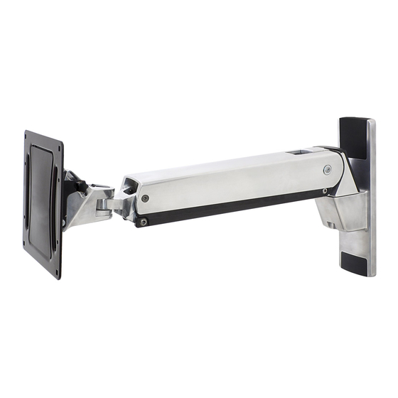
- Page 1 PLAY70 INTERACTIVE TV MOUNT INSTRUCTION MANUAL CAUTION! CAUTION! MAXIMUM WEIGHT CAPACITY MAXIMUM SCREEN SIZE 60+” 70 LBS 31.8 KG Reduce.Reuse.Recycle 1 of 25 PN:888-45-254-W-01 revF 05/15...
- Page 2 DISCLAIMER - WARNING INFORMATION Disclaimer – OmniMount Systems, Inc. has extended every effort to ensure to accuracy and completeness of this manual. However, OmniMount Systems, Inc. does not claim that the information covers all installation or operational variables. The information contained in this document is subject to change without notice or obligation of any kind.
- Page 3 CONTENTS CONTENTS Part Quantity Description Wall Plate Arm/Wall Plate Hardware Wall Plate Covers Rear Arm Cover CFT Arm 200x200 VESA Monitor Plate Spider Adapters Screws/Hardware For Flat Panel 697-613-00 Wall Kit ST8x3 697-688-00 Part Quantity Description Part Quantity Description Philips screws M4 x 15mm Lag Bolt Philips screws M4 x 30mm Round Washers...
- Page 4 Tools Needed CAUTION! CAUTION! MAXIMUM WEIGHT CAPACITY MAXIMUM SCREEN SIZE 60+” Tools Needed 70 LBS 31.8 KG 13mm and 8mm PN:888-45-254-W-01 revF 05/15 8 of 25...
- Page 5 STEP 1 - Placement of Arm on the Wall INSTRUCTIONS 1. MOUNTING CONSIDERATIONS: • Wall Mount Bracket MUST be attached to a stud or solid concrete. DO NOT attach this product to hollow wall or any other confi guration. • Make sure Arm will have desired unobstructed range of motion: up-down, side-to-side, in-out (see section RANGE OF MOTION). •...
- Page 6 STEP 2 - Wood Stud Installation Wood Stud Mount 7/32 x 2.75" 5.5mm x 70mm PN:888-45-254-W-01 revF 05/15 10 of 25...
- Page 7 STEP 2 - Solid Wall Installation Solid Wall Mount 3/8 x 2.75" 9.5 - 10mm x 70mm PN:888-45-254-W-01 revF 05/15 11 of 25...
- Page 8 STEP 3 65mm Washer 16mm Bearing Spring Disc 25mm Washer NOTE: Part# P-H must be concave face down for proper assembly. 12 of 25 PN:888-45-254-W-01 revF 05/15...
- Page 9 STEP 4 200mm (7-7/8”) 100 x 200 200 x 200 200mm (7-7/8”) 200 x 300 200 x 400 600mm (23-5/8”) 400mm (15-3/4”) 300 x 300 300mm (11-13/16”) 300 x 400 400 x 400 600 x 400 400mm (15-3/4”) 300mm (11-13/16”) 300 x 200 400 x 200 13 of 25...
- Page 10 STEP 5-A - Monitor Installation 200mm (7-7/8”) 100 x 200 200 x 200 200mm (7-7/8”) WARNING! PLEASE SELECT THE PROPER SCREW LENGTH FOR YOUR FLAT PANEL BY HAND TIGHTENING TO CHECK YOUR FLAT PANELS THREAD DEPTH. 14 of 25 PN:888-45-254-W-01 revF 05/15...
- Page 11 STEP 5-B,C,D - Adapter Installation 300 x 200 200 x 300 300 x 300 200 x 400 300 x 400 400 x 200 400 x 400 600 x 400 200mm 600mm 400mm 400mm 300mm 300mm 15 of 25 PN:888-45-254-W-01 revF 05/15...
- Page 12 STEP 5-B,C,D - Monitor Installation B / C / D WARNING! PLEASE SELECT THE PROPER SCREW LENGTH FOR YOUR FLAT PANEL BY HAND TIGHTENING TO CHECK YOUR FLAT PANELS THREAD DEPTH. 16 of 25 PN:888-45-254-W-01 revF 05/15...
- Page 13 STEP 6 17 of 25 PN:888-45-254-W-01 revF 05/15...
- Page 14 It is important that you adjust this product according to the weight of the mounted equipment as described in the following steps. Any time equipment is added or removed from this product, resulting in a change in the weight of the mounted load, you should repeat these adjustment steps to ensure safe and optimum operation.
- Page 15 STEP 7 Lift – Up and down Tilt – Forward and Backward PN:888-45-254-W-01 revF 05/15 19 of 25...
- Page 16 STEP 8 Lift – Up and down 10 mm PN:888-45-254-W-01 revF 05/15 20 of 25...
- Page 17 STEP 9 PN:888-45-254-W-01 revF 05/15 21 of 25...
- Page 18 STEP 10 CAUTION! The bottom nut will turn during adjustment of the top nut; DO NOT apply any tool to the bottom nut. Serious damage to the Arm may occur if these instructions are not followed. PN:888-45-254-W-01 revF 05/15 22 of 25...
- Page 19 STEP 11 Tilt – Forward and Backward PN:888-45-254-W-01 revF 05/15 23 of 25...
- Page 20 OmniMount disclaims any other warranties, expressed or implied, including warranties of fi tness for a particular purpose and warranties of merchantability. OmniMount will not be liable for any damages arising out of the use of, or inability to use, OmniMount products. OmniMount bears no responsibility for incidental or consequential damages. This includes, but is not limited to, any labor charges for the repair of OmniMount products performed by anyone other than OmniMount.
- Page 21 THANK YOU Thank you for purchasing an OmniMount product...