Table of Contents
Advertisement
Quick Links
Instruction Manual
D103785X012
™
Fisher
FIELDVUE
Controller
This manual applies to
Instrument Level
Device Type
Device Revision
Hardware Revision
Firmware Revision
DD Revision
Contents
. . . . . . . . . . . . . . . . . . . . . . . . . . . . . .
. . . . . . . . . . . . . . . . . . . . . . . . . . . . . . . . . .
. . . . . . . . . . . . . . . . . . . . . . . . . . . . . . . .
. . . . . . . . . . . . . . . . . . . . . . . . . . .
. . . . . . . . . . . . . . . . . . . . . . . . . . .
. . . . . . . . . . . . . . . . . . . . . . . . . . . . . . . . .
. . . . . . . . . . . . . . . . . . . . . . . . . . . .
. . . . . . . . . . . . . . . . . . . . . . . .
. . . . . . . . . . . . . . . . . . . . . . . . .
. . . . . . . . . . . . . . . . . . . . . . . . . . . . . . .
. . . . . . . . . . . . . . . . . . . . . . . . . . . . . . .
. . . . . . . . . . . . . . . . . . . . . . . .
. . . . . . . . . . . . . . . . . . . . . . . .
. . . . . . . . . . . . . . . . . . . . . . . . . . . . . . . .
. . . . . . . . . . . . . . . . . . . . . . . . . . .
. . . . . . . . . . . . . . . . . . . . . . . . .
. . . . . . . . . . . . . . . . . . . . . . . . . . . . . . . . . .
. . . . . . . . . . . . . . . . . . . . . . . . . . .
. . . . . . . . . . . . . . . . . . . . . . . . . . . .
. . . . . . . . . . . . . . . . . . . . . . . . . . . . .
www.Fisher.com
™
DVC6000 HW2 Digital Valve
HC, AD, PD, ODV
130b
1 & 2
2
6
4 & 5
. . . . . . . . . . . . . . . . .
. . . . . . . . . . . . . . . .
. . . . . . . . . . . . . .
. . . . . . . . . . . . . . . . . .
. . . .
. . . . . . . . . . . . . . . . .
. . . . . . . . . . . . . . .
. . . . . . . . . . . . . . . . . . . . . . .
. . . . . . . . . . . . . . . . . . . .
3
3
3
3
4
7
8
9
9
9
9
11
12
12
17
19
. . . . . . . . . . . . . . . . . . . . . . . . . . . . . . . . . . . .
19
19
20
20
20
20
. . . . . . . . . . . . . . . . . . . . . . . . . . . . . . . . . . .
20
21
21
21
21
22
22
DVC6000 HW2 Digital Valve Controller
. . . . . . . . . . . . . . . . . . . . . .
. . . . . . . . . . . . . . . . . . .
. . . . . . . . . . . . . . . . . . . . . . .
. . . . . . . . . . . . . . . .
. . . . . . . . . . . . . . . . . . . . . . . .
. . . . . . . . . . . . . . . . . . . . . . . .
. . . . . . . . . . . . . . . . . . . . . . . . . .
. . . . . . . . . . . . . . . . . . . . . . . .
. . . . . . . . . . . . . . . . . . . . . .
. . . . . . . . . . . . . . . . . . . . . . . . . . .
. . . . . . . . . . . . . . . . . . . . . . . .
. . . . . . . . . . . . . . . . . . . . . . . . . .
. . . . . . . . . . . . . . . . . . . . . . . . . .
. . . . . . . . . . . . . . . . . . . .
. . . . . . . . . . . . . .
. . . . . . . . . . . . . . . . . . . . .
. . . . . . . . . . . . . . . . . . . . . . . . . . . .
. . . . . . . . . . . . . . . . . . . . . . . . . . . . . . . . .
. . . . . . . . . . . . . . . . . . . .
June 2017
22
22
23
23
24
24
25
25
27
28
28
31
. . . . . . . . . .
31
32
34
37
. . . . . . . . . . . .
37
37
38
38
38
39
40
Advertisement
Table of Contents
Troubleshooting

Related Manuals for Emerson Fisher FIELDVUE DVC6000 HW2


Summary of Contents for Emerson Fisher FIELDVUE DVC6000 HW2
-
Page 1: Table Of Contents
Instruction Manual DVC6000 HW2 Digital Valve Controller D103785X012 June 2017 ™ ™ Fisher FIELDVUE DVC6000 HW2 Digital Valve Controller This manual applies to Instrument Level HC, AD, PD, ODV Device Type 130b Device Revision 1 & 2 Hardware Revision Firmware Revision DD Revision 4 &... - Page 2 Instruction Manual DVC6000 HW2 Digital Valve Controller June 2017 D103785X012 Contents (continued) Replacing the Module Base ....Submodule Maintenance ..... . Section 4 Calibration .
-
Page 3: Section 1 Introduction
Refer to the DVC6005 Series Remote Mount quick start guide (D103784X012) for DVC6000 HW2 installation, connection and initial configuration information. If a copy of this quick start guide is needed contact your Emerson sales office or Local Business Partner, or visit our website at Fisher.com. -
Page 4: Specifications
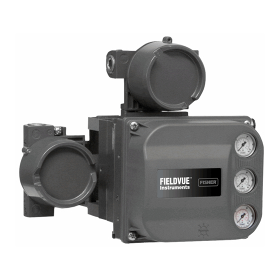
Instruction Manual Introduction June 2017 D103785X012 Using a personal computer and ValveLink software or Figure 1‐1. DVC6000 HW2 Digital Valve Controller AMS Suite: Intelligent Device Manager, or a Field Mounted on Rotary Control Valve/Actuator Communicator, you can perform several operations with the DVC6000 HW2 digital valve controller. - Page 5 Instruction Manual Introduction D103785X012 June 2017 Table 1‐2. Specifications Available Mounting Per ISA Standard 7.0.01: A maximum 40 micrometer particle size in the air system is acceptable. Further DVC6000 HW2 digital valve controllers can be filtration down to 5 micrometer particle size is mounted on Fisher and other manufacturers rotary recommended.
- Page 6 PESO CCOE— Petroleum and Explosives Safety Organisation - Chief Controller of Explosives (India) Meets EN 61326-1:2013 Immunity—Industrial locations per Table 2 of Contact your Emerson sales office or Local Business the EN 61326-1 standard. Performance is Partner for classification/certification specific shown in table 1‐3 below.
-
Page 7: Related Documents
Engineering Practice (SEP) and cannot bear the CE Supply Voltage: 30 VDC maximum marking related to PED compliance. Reference Accuracy: 2% of travel span Contact your Emerson sales office, Local Business However, the product may bear the CE marking to Partner, or go to Fisher.com... -
Page 8: Educational Services
D ValveLink Software Help or Documentation All documents are available from your Emerson sales office or Local Business Partner, or at Fisher.com. Educational Services For information on available courses for the DVC6000 HW2 digital valve controller, as well as a variety of other... -
Page 9: Section 2 Wiring Practices
To determine if your system requires a filter contact your Emerson sales office or Local Business Partner. Note A HART filter is typically NOT required for any of the Emerson Automation Solutions control systems, including PROVOXt, RS3t, and DeltaVt systems. Figure 2‐1. HART Filter Application NON‐HART BASED DCS... - Page 10 Instruction Manual Wiring Practices June 2017 D103785X012 As shown in figure 2‐2, the voltage available at the instrument depends upon: D the control system compliance voltage D if a filter, wireless THUM adapter, or intrinsic safety barrier is used, and D the wire type and length. The control system compliance voltage is the maximum voltage at the control system output terminals at which the control system can produce maximum loop current.
-
Page 11: Compliance Voltage
3. Increase the resistance of the 1 kW potentiometer, shown in figure 2‐3, until the current observed on the milliammeter begins to drop quickly. 4. Record the voltage shown on the voltmeter. This is the control system compliance voltage. For specific parameter information relating to your control system, contact your Emerson sales office or Local Business Partner. -
Page 12: Auxiliary Terminal Wiring Length Guidelines
Instruction Manual Wiring Practices June 2017 D103785X012 Auxiliary Terminal Wiring Length Guidelines The Auxiliary Input Terminals of a DVC6000 HW2 with instrument level ODV can be used with a locally‐mounted switch for initiating a partial stroke test. Some applications require that the switch be installed remotely from the DVC6000 HW2. - Page 13 The DVC6005 HW2 base unit is designed to receive travel information via a remote sensor. The remote can be any of the following: D Emerson Automation Solutions supplied DVC6015, DVC6025 or DVC6035 remote feedback unit; refer to the DVC6005 Series Remote Mount Digital Valve Controller quick start guide (D103784X012) that ships with the product, D An under‐traveled 10 kOhm potentiometer used in conjunction with onboard 30 kOhm resistor, or...
- Page 14 Instruction Manual Wiring Practices June 2017 D103785X012 Note The digital valve controller must be configured using the SStem/Roller selection on the menu of the appropriate setup device. The DVC6005 HW2 base unit was designed to work with a 40 kOhm potentiometer for travel feedback. However, there are linear potentiometers that are readily available with a rated resistance of 10 kOhm.
- Page 15 Instruction Manual Wiring Practices D103785X012 June 2017 Using a Potentiometer with Two Fixed Resistors as a Remote Travel Sensor Perform the following procedure if a potentiometer is used with the same, or slightly longer travel than the actuator's travel. Note The potentiometer must be capable of resistance close to 0 Ohms.
- Page 16 Instruction Manual Wiring Practices June 2017 D103785X012 Figure 2‐5. Terminal Details for Connecting a FIELDVUE DVC6005 HW2 Base Unit and a Three‐Resistor Series 30kW " (R1) BASE UNIT TERMINATION BOX THREE‐RESISTOR SERIES (DVC6005 HW2) 3. Install the fixed resistor (R ) across the unlabeled bottom Terminal and Terminal #1.
-
Page 17: Installation In Conjunction With A Rosemountt 333 Hart Tri-Loopt Hart-To-Analog Signal Converter
Instruction Manual Wiring Practices D103785X012 June 2017 Installation in Conjunction with a Rosemount 333 HART Tri‐Loop HART‐to‐Analog Signal Converter Use the DVC6000 HW2 digital valve controller in operation with a Rosemount 333 HART Tri‐Loop HART‐to‐Analog Signal Converter to acquire an independent 4‐20 mA analog output signal for the analog input, travel target, pressure, or travel. - Page 18 Instruction Manual Wiring Practices June 2017 D103785X012 Commissioning the Digital Valve Controller for use with the HART Tri‐Loop Signal Converter To prepare the digital valve controller for use with a 333 HART Tri‐Loop, you must configure the digital valve controller to burst mode, and select Burst Command 3.
-
Page 19: Section 3 Configuration
Instruction Manual Configuration D103785X012 June 2017 Section 3 Configuration Guided Setup Field Communicator Configure > Guided Setup (2‐1) The following procedures will guide you through the instrument setup process. D Device Setup—This procedure is used to configure actuator and valve information, calibrate the valve assembly, and assign the tuning set for the valve assembly. -
Page 20: Mode And Protection
Instruction Manual Configuration June 2017 D103785X012 Table 3‐1. Default Detailed Setup Parameters (continued) Setup Parameter Default Setting Travel Deviation Alert Enable Travel Deviation Alert Point Travel Deviation Time 9.99 sec Pressure Deviation Alert Enable Deviation & Other Alerts Pressure Deviation Alert Point 5 psi Pressure Deviation Alert Time 5.0 sec... -
Page 21: Serial Numbers
Instruction Manual Configuration D103785X012 June 2017 D Description—Enter a description for the application with up to 16 characters. The description provides a longer user‐defined electronic label to assist with more specific instrument identification than is available with the HART tag. D Message—Enter any message with up to 32 characters. Message provides the most specific user‐defined means for identifying individual instruments in multi‐instrument environments. -
Page 22: Spec Sheet
Instruction Manual Configuration June 2017 D103785X012 D Input Range Lo—Permits setting the Input Range Low value. Input Range Low should correspond to Travel Range Low, if the Zero Power Condition is configured as closed. If the Zero Power Condition is configured as open, Input Range Low corresponds to Travel Range High. -
Page 23: Cutoffs And Limits
Instruction Manual Configuration D103785X012 June 2017 D Fallback-Sensor/Tvl Deviation—The instrument will fallback to pressure control if a travel sensor failure is detected, or if the Tvl Dev Press Fallback setting is exceeded for more than the Tvl Dev Press Fallback Time. Note Travel / Pressure Select must be set to Travel for double‐acting actuators Cutoffs and Limits... -
Page 24: Pressure Control
Instruction Manual Configuration June 2017 D103785X012 D EPPC Set Point—Used in conjunction with End Point Pressure Control, End Point Pressure Control Set Point allows you to select a pressure to be delivered by the instrument at the travel extreme. For a fail‐closed valve, this pressure must be sufficient to maintain the fully open position. -
Page 25: Control Mode
Instruction Manual Configuration D103785X012 June 2017 Control Mode D Control Mode—Displays the current control mode of the instrument. This will show Analog if the instrument is in PointtoPoint mode and is using a 420 mA signal for its power and set point. This will show Digital if the instrument is in Multidrop mode and is using 24 VDC for power and a digital set point for control. - Page 26 Instruction Manual Configuration June 2017 D103785X012 Figure 3‐2. Travel Target Versus Ranged Set Point, for Various Input Characteristics (Zero Power Condition = Closed) Ranged Set Point, % Ranged Set Point, % Input Characteristic = Linear Input Characteristic = Equal Percentage Ranged Set Point, % Input Characteristic = Quick Opening A6535‐1...
-
Page 27: Dynamic Response
Instruction Manual Configuration D103785X012 June 2017 Dynamic Response D SP Rate Open—Maximum rate (% of valve travel per second) at which the digital valve controller will move to the open position regardless of the rate of input current change. A value of 0 will deactivate this feature and allow the valve to stroke open as fast as possible. -
Page 28: Tuning
Instruction Manual Configuration June 2017 D103785X012 Tuning Field Communicator Configure > Manual Setup > Tuning (2‐2-4) Travel Tuning WARNING Changes to the tuning set may cause the valve/actuator assembly to stroke. To avoid personal injury and property damage caused by moving parts, keep hands, tools, and other objects away from the valve/actuator assembly. D Travel Tuning Set There are eleven tuning sets to choose from. - Page 29 Instruction Manual Configuration D103785X012 June 2017 Table 3‐4. Actuator Information for Initial Setup Starting Actuator Actuator Feedback Travel Sensor Motion Actuator Size Actuator Style Tuning Manufacturer Model Connection Relay A or C Piston Dbl with or SStem-Standard w/out Spring. See for travels up to Depends upon pneumatic connections.
- Page 30 Instruction Manual Configuration June 2017 D103785X012 D Integral Enable—Yes or No. Enable the integral setting to improve static performance by correcting for error that exists between the travel target and actual travel. Travel Integral Control is enabled by default. D Integral Gain—Travel Integral Gain is the ratio of the change in output to the change in input, based on the control action in which the output is proportional to the time integral of the input.
-
Page 31: Pressure Tuning
Instruction Manual Configuration D103785X012 June 2017 Pressure Tuning D Pressure Tuning Set There are twelve Pressure Tuning Sets to choose from. Each tuning set provides a preselected value for the digital valve controller gain settings. Tuning set C provides the slowest response and M provides the fastest response. Tuning set B is appropriate for controlling a pneumatic positioner. -
Page 32: Valve And Actuator
Instruction Manual Configuration June 2017 D103785X012 D Integrator Limit—The Integrator Limit provides an upper limit to the integrator output. The high limit is configurable from 0 to 100% of the I/P drive signal. Valve and Actuator Field Communicator Configure > Manual Setup > Valve and Actuator (2‐2‐5) Valve Style—Enter the valve style, rotary or sliding‐stem Actuator Style—Enter the actuator style, spring and diaphragm, piston double‐acting without spring, piston single‐acting with spring, or piston double‐acting with spring. - Page 33 Instruction Manual Configuration D103785X012 June 2017 Zero Power Condition—The position of the valve (open or closed) when the electrical power to the instrument is removed. Zero Power Condition (ZPC) is determined by relay type, as shown in figure 3‐5. Figure 3‐5. Zero Power Condition Relay Type Loss of Electrical Power Single‐Acting Direct (Relay A or C)
-
Page 34: Partial Stroke Test
Instruction Manual Configuration June 2017 D103785X012 Partial Stroke Test (PST) (Instrument Level ODV only) Field Communicator Configure > Manual Setup > Partial Stroke (2-2-6) Note Partial Stroke is only available for instrument level ODV. Partial Stroke Test (PST) D PST Pressure Limit— This defines the actuator pressure at which a partial stroke test will abort. This prevents the DVC6000 HW2 from exhausting (or building) excessive pressure to the actuator in an attempt to move a stuck valve. - Page 35 Instruction Manual Configuration D103785X012 June 2017 Table 3‐6. Values for Disabling Partial Stroke Pressure Limit Actuator Type Relay Type Zero Power Condition Partial Stroke Start Point Partial Stroke Pressure Limit (Disabled) Open Closed Closed Psupply A or C Open Psupply Open Closed Single Acting...
- Page 36 Instruction Manual Configuration June 2017 D103785X012 PST Enable—Yes or No. This enables or disables the Partial Stroke Test. PST Start Point—Valve Open or Valve Closed. This defines the travel stop that the valve needs to be at before a partial stroke test can be initiated.
-
Page 37: Outputs
Instruction Manual Configuration D103785X012 June 2017 Outputs Field Communicator Configure > Manual Setup > Outputs (2-2-6) HC, AD, PD or (2-2-7) ODV Note These menu items are only available on units that have the optional 420 mA position transmitter or switch hardware installed. Output Terminal Configuration D Output Terminal Enable—If using the optional output terminal for a Position Transmitter or Switch output, this must be Enabled. -
Page 38: Hart Variable Assignments
Instruction Manual Configuration June 2017 D103785X012 HART Variable Assignments Instrument variables can be reported via four different HART variable assignments. The Primary Variable is always configured as Analog Input. However, the remaining three variables have additional options as listed below. Primary Variable (PV) Analog Input Secondary Variable (SV) -
Page 39: Alert Setup
Instruction Manual Configuration D103785X012 June 2017 Alert Setup Field Communicator Configure > Alert Setup (2‐3) An alert is a notification that the instrument has detected a problem. A shutdown is an action that the instrument takes to drive the air output to the Zero Power Condition as per figure 3‐5. Some alerts can be configured to shutdown the instrument. -
Page 40: Change To Hart 5 / Hart 7
Instruction Manual Configuration June 2017 D103785X012 Change to HART 5 / Change to HART 7 Field Communicator Service Tool > Maintenance > Change to HART 5 / Change to HART 7 (3-5-3) HC or (3-5-4) AD, PD or (3-5-5) ODV Note This procedure must never be done while the valve is in service and controlling the process. -
Page 41: Section 4 Calibration
Instruction Manual Calibration D103785X012 June 2017 Section 4 Calibration Calibration Overview When a DVC6000 HW2 digital valve controller is ordered as part of a control valve assembly, the factory mounts the remote feedback unit on the actuator and connects the necessary tubing, then sets up and calibrates the controller. For digital valve controllers that are ordered separately, recalibration of the analog input or pressure sensors generally is unnecessary. -
Page 42: Travel Calibration
Instruction Manual Calibration June 2017 D103785X012 Travel Calibration If a double‐acting relay is used, you will be prompted to run the relay adjustment when auto or manual calibration is selected. Select Yes to adjust the relay, select No to proceed with calibration. For additional information, refer to Relay Adjustment on page 52. - Page 43 Instruction Manual Calibration D103785X012 June 2017 Figure 4‐1. Crossover Point ACTUATOR STEM FEEDBACK A6536-3 7. Place the instrument In Service and verify that the travel properly tracks the current source. If the unit does not calibrate, refer to table 4‐1 for error messages and possible remedies. Table 4‐1.
-
Page 44: Manual Calibration
Instruction Manual Calibration June 2017 D103785X012 Manual Calibration Two procedures are available to manually calibrate travel: D Analog Adjust— This procedure is used when you can manually change the 4-20 mA current source to move the valve. D Digital Adjust— This procedure is used when the 4-20 mA current source cannot be manually changed. Analog Calibration Adjust Connect a variable current source to the instrument LOOP + and LOOP - terminals. -
Page 45: Pushbutton Calibration
Instruction Manual Calibration D103785X012 June 2017 2. From the adjustment menu, select the direction and size of change required to set the travel at 0%. Selecting large, medium, and small adjustments causes changes of approximately 10.0%, 1.0%, and 0.1%, respectively. If another adjustment is required, repeat step 2. Otherwise, select Done and go to step 3. 3. -
Page 46: Sensor Calibration
Instruction Manual Calibration June 2017 D103785X012 Sensor Calibration Pressure Sensors Note The pressure sensor is calibrated at the factory and should not require calibration. Output Pressure Sensor To calibrate the output pressure sensor, connect an external reference gauge to the output being calibrated. The gauge should be capable of measuring maximum instrument supply pressure. -
Page 47: Travel Sensor
Instruction Manual Calibration D103785X012 June 2017 Supply Pressure Sensor Note Supply Pressure Sensor Calibration is not available for instrument level HC. To calibrate the supply pressure sensor, connect an external reference gauge to the output side of the supply regulator. The gauge should be capable of measuring maximum instrument supply pressure. Follow the prompts on the Field Communicator display to calibrate the instrument's supply pressure sensor. - Page 48 Instruction Manual Calibration June 2017 D103785X012 2. As shown in figure 4‐2, align the feedback arm (key 79) with the housing by inserting the alignment pin (key 46) through the hole marked “A” on the feedback arm. Fully engage the alignment pin into the tapped hole in the housing.
- Page 49 Instruction Manual Calibration D103785X012 June 2017 Figure 4‐3. Travel Indicator Assembly Starting Position; Counterclockwise or Clockwise DVC6035 FEEDBACK ARM MOVEMENT DVC6035 FEEDBACK ARM MOVEMENT ACTUATOR SHAFT MOVEMENT ACTUATOR SHAFT MOVEMENT STARTING POSITION OF THE TRAVEL INDICATOR ASSEMBLY STARTING POSITION OF THE TRAVEL INDICATOR ASSEMBLY IF IF INCREASING PRESSURE FROM OUTPUT A DRIVES THE INCREASING PRESSURE FROM OUTPUT A DRIVES THE INDICATOR INDICATOR COUNTERCLOCKWISE.
- Page 50 Instruction Manual Calibration June 2017 D103785X012 Figure 4‐4. FIELDVUE DVC6025 Digital Valve Controller Mounted on Fisher 2052, Size 33 Actuator CAP SCREW, HEX SOCKET (KEY 116) MOUNTING ADAPTER (KEY 117) MOUNTING BRACKET (KEY 74) BIAS SPRING (KEY 82) FEEDBACK ARM ASSEMBLY (KEY 84) ARM ASSEMBLY (KEY 91)
-
Page 51: Analog Input Calibration
Instruction Manual Calibration D103785X012 June 2017 Note In the next step, be sure the arm assembly outer surface remains flush with the end of the travel sensor shaft. 7. While observing the travel sensor counts, tighten the screw that secures the arm assembly to the travel sensor shaft. -
Page 52: Relay Adjustment
Instruction Manual Calibration June 2017 D103785X012 3. The value of the Analog Input appears on the display. Press OK to display the adjustment menu. 4. From the adjustment menu, select the direction and size of adjustment to the displayed value. Selecting large, medium, and small adjustments causes changes of approximately 0.4 mA, 0.04 mA, and 0.004 mA, respectively. -
Page 53: Single-Acting Relays
Instruction Manual Calibration D103785X012 June 2017 If the low bleed relay option has been ordered stabilization may take approximately two minutes longer than the standard relay. Relay A may also be adjusted for use in single‐acting‐ direct applications. Rotate the adjustment disc as shown in figure 4‐6 for single‐acting direct operation. -
Page 54: Pst Calibration
Instruction Manual Calibration June 2017 D103785X012 PST Calibration (ODV Instrument Level only) This procedure permits you to run the Partial Stroke Calibration, which enables the Partial Stroke Test. It establishes values for Partial Stroke Pressure Limit, Pressure Set Point and Pressure Saturation Time for End Point Pressure Control, Travel Deviation Alert Point and Travel Deviation Time. -
Page 55: Section 5 Device Information, Diagnostics, And Alerts
Instruction Manual Device Information, Diagnostics, and Alerts D103785X012 June 2017 Section 5 Device Information, Diagnostics, and Alerts55 Overview Field Communicator Overview (1) Status & Primary Purpose Variables The overview section provides basic information about the current state of the instrument and gives you access to the current values of: D Alert Status D Communication Status... -
Page 56: Service Tools
Instruction Manual Device Information, Diagnostics, and Alerts June 2017 D103785X012 Service Tools Field Communicator Service Tools (3) Device Status Instrument alerts, when enabled, detect many operational and performance issues that may be of interest. If there are no alerts currently active, this display will be empty. Alert Record The DVC6000 HW2 will store 20 alerts. -
Page 57: Pressure
Instruction Manual Device Information, Diagnostics, and Alerts D103785X012 June 2017 D Variable Out of Range—This alert is active if one or more of the measured analog sensor readings (loop current, pressure, temperature, or travel) is saturated or reading out of its configured range. The condition may be due to improper configuration or physical setup and not be due to a sensor malfunction. -
Page 58: Travel
Instruction Manual Device Information, Diagnostics, and Alerts June 2017 D103785X012 Travel Note The Travel Alert Deadband applies to the Travel Deviation Alert as well as the Travel Alert Hi, Lo, Hi Hi, and Lo Lo. D Travel Deviation Alert—If the difference between the Travel Target and the Travel exceeds the Travel Deviation Alert Point for more than the Travel Deviation Time, the Travel Deviation Alert is active. -
Page 59: Travel History
Instruction Manual Device Information, Diagnostics, and Alerts D103785X012 June 2017 Travel History D Cycle Count High Alert—This alert is active if the Cycle Counter exceeds the Cycle Count Alert Point. The Cycle Count records the number of times the travel changes direction when it is outside of the deadband. To clear the alert, set the Cycle Counter to a value less than the alert point. -
Page 60: Status
Instruction Manual Device Information, Diagnostics, and Alerts June 2017 D103785X012 Status D Calibration in Progress Alert—This alert is active when calibration is in progress. D AutoCal in Progress Alert—This alert is active when auto calibration is in progress. D Diagnostic in Progress Alert—This alert is active when a diagnostic test is in progress. D Diagnostic Data Available Alert—This alert is active when diagnostic data has been collected and is being stored in the instrument. -
Page 61: Variables
Instruction Manual Device Information, Diagnostics, and Alerts D103785X012 June 2017 When enabled, a partial stroke test may be initiated by the device (as a scheduled, auto partial stroke test), a remote pushbutton located in the field or at the valve, a Field Communicator, or ValveLink software. D Automatic (Scheduled) The Auto Partial Stroke Test allows the partial stroke test to be scheduled by the DVC6000 HW2. - Page 62 Instruction Manual Device Information, Diagnostics, and Alerts June 2017 D103785X012 D Actuator Pressure(s) D Travel/Pressure Control Configuration (also provides a procedure to modify) D Control Mode (also provides a procedure to modify) D Instrument Temperature D Travel Counts (this is the raw travel sensor reading used for advanced adjustments) D Maximum Recorded Temperature D Minimum Recorded Temperature D Number of Power Ups...
-
Page 63: Section 6 Maintenance And Troubleshooting
Instruction Manual Maintenance and Troubleshooting D103785X012 June 2017 Section 6 Maintenance and Troubleshooting66 The DVC6000 HW2 digital valve controller enclosure is rated Type 4X and IP66, therefore periodic cleaning of internal components is not required. If the DVC6000 HW2 is installed in an area where the exterior surfaces tend to get heavily coated or layered with industrial or atmospheric contaminants, it is recommended that the vent (key 52) be periodically removed and inspected to ensure there is no partial or full obstruction. -
Page 64: Module Base Maintenance
Instruction Manual Maintenance and Troubleshooting June 2017 D103785X012 CAUTION When replacing components, use only components specified by the factory. Always use proper component replacement techniques, as presented in this manual. Improper techniques or component selection may invalidate the approvals and the product specifications, as indicated in table 1‐2. - Page 65 Instruction Manual Maintenance and Troubleshooting D103785X012 June 2017 1. For sliding‐stem applications only, a protective shield for the feedback linkage is attached to the side of the module base assembly as shown in figure 6‐1. Remove this shield and keep for reuse on the replacement module. The replacement module will not have this protective shield.
-
Page 66: Replacing The Module Base
Instruction Manual Maintenance and Troubleshooting June 2017 D103785X012 Figure 6‐2. Printed Wiring Board Cable Connections TERMINAL BOX REMOTE MODULE BASE TERMINAL BOX ASSEMBLY HOUSING CABLE TO REMOTE PRINTED WIRING TERMINAL BOX CABLE TO BOARD ASSEMBLY TERMINAL BOX X0921 Replacing the Module Base To replace the DVC6005 HW2 module base perform the following steps. -
Page 67: Submodule Maintenance
Instruction Manual Maintenance and Troubleshooting D103785X012 June 2017 WARNING Personal injury, property damage, or disruption of process control can result if the cable assemblies/wiring are damaged when attaching the cover to the module base assembly. Ensure that the cable assemblies/ wiring are positioned in the cavity of the module base so they do not get compressed or damaged when attaching the cover to the module base assembly in step 6. - Page 68 Instruction Manual Maintenance and Troubleshooting June 2017 D103785X012 3. Install a new screen in the supply port as shown in figure 6‐3. 4. Inspect the O‐ring (key 39) in the I/P output port; if necessary, replace it. 5. Reinstall the I/P converter (key 41) and shroud (key 169) as described in the Replacing the I/P Converter procedure. Figure 6‐3.
-
Page 69: Printed Wiring Board (Pwb) Assembly
Instruction Manual Maintenance and Troubleshooting D103785X012 June 2017 Figure 6‐4. I/P Converter SHROUD (KEY 169) I/P CONVERTER SOCKET‐HEAD (KEY 41) SCREWS (4) (KEY 23) BOOTS (KEY 210) W9328 PWB (Printed Wiring Board) Assembly Refer to figure 7‐2 for key number locations. The PWB assembly (key 50) is located on the back of the module base assembly (key 2). - Page 70 Instruction Manual Maintenance and Troubleshooting June 2017 D103785X012 5. Set the DIP switch on the PWB assembly according to table 6‐2. On units that have the optional 4-20 mA position transmitter or switch hardware installed, set the Transmitter or Switch option according to table 6‐3. Table 6‐2.
-
Page 71: Pneumatic Relay
Instruction Manual Maintenance and Troubleshooting D103785X012 June 2017 Pneumatic Relay Refer to figure 7‐2 for key number locations. The pneumatic relay (key 24) is located on the front of the module base. Note After relay submodule replacement, calibrate the digital valve controller to maintain accuracy specifications. Removing the Pneumatic Relay 1. -
Page 72: Gauges, Pipe Plugs Or Tire Valves
Instruction Manual Maintenance and Troubleshooting June 2017 D103785X012 Gauges, Pipe Plugs, or Tire Valves Depending on the options ordered, the DVC6000 HW2 will be equipped with either gauges (key 47), pipe plugs (key 66), or tire valves (key 67). Single‐acting direct instruments will also have a screen (key 236, figure 7‐3). These are located on the top of the module base next to the relay. -
Page 73: Replacing The Terminal Box
Instruction Manual Maintenance and Troubleshooting D103785X012 June 2017 Replacing the Terminal Box Note Inspect all O‐rings for wear and replace as necessary. 1. Install two wire retainers (key 44), internal and external to the terminal box. 2. Apply silicone lubricant to the O‐ring (key 34) and install the O‐ring over the stem of the terminal box. 3. -
Page 74: Disassembly
Instruction Manual Maintenance and Troubleshooting June 2017 D103785X012 Disassembly Note If the feedback arm (key 79) or feedback arm assembly (key 84) is removed from the digital valve controller, the travel sensor assembly [i.e. potentiometer/bushing assembly (key 223)] must be recalibrated. DVC6015 Remote Feedback Unit Refer to figure 7‐4 for key number locations. -
Page 75: Dvc6025 Remote Feedback Unit
Instruction Manual Maintenance and Troubleshooting D103785X012 June 2017 DVC6025 Remote Feedback Unit Refer to figure 7‐5 for key number locations. 1. Remove piping and fittings from the instrument. 2. Remove the instrument from the actuator. 3. Disconnect the bias spring (key 82) from the feedback arm assembly (key 84) and the arm assembly (key 91). Remove the mounting bracket (key 74) from the back of the digital controller. -
Page 76: Dvc6025 Feedback Unit
Instruction Manual Maintenance and Troubleshooting June 2017 D103785X012 5. Using a Field Communicator, perform the appropriate Travel Sensor Adjust procedure in the Calibration section. Install the remote feedback unit on the actuator when the travel sensor adjustment is complete. Note If a Field Communicator is not available, perform the Travel Sensor Adjustment with Multimeter procedure below. - Page 77 Instruction Manual Maintenance and Troubleshooting D103785X012 June 2017 Figure 6‐8. Remote Feedback Terminals; Potentiometer Resistance Measurement TERMINAL 2 TERMINAL 3 TERMINAL 1 5. Using a Field Communicator, perform the appropriate Travel Sensor Adjust procedure in the Calibration section. Install the remote feedback unit on the actuator when travel sensor adjustment is complete. Note If a Field Communicator is not available, perform the Travel Sensor Adjustment with Multimeter procedure below.
-
Page 78: Dvc6035 Feedback Unit
Instruction Manual Maintenance and Troubleshooting June 2017 D103785X012 6. While observing the resistance, tighten the screw (key 80) to secure the feedback arm to the travel sensor shaft. Be sure the resistance reading remains at the calculated resistance determined in step 2, $100 ohms. Paint the screw to discourage tampering with the connection. - Page 79 Instruction Manual Maintenance and Troubleshooting D103785X012 June 2017 4. Loosely assemble the bias spring (key 78), screw (key 80), plain washer (key 163), and nut (key 81) to the feedback arm (key 79), if not already installed. 5. Attach the feedback arm (key 79) to the travel sensor shaft. 6.
-
Page 80: Troubleshooting
Instruction Manual Maintenance and Troubleshooting June 2017 D103785X012 Troubleshooting If communication or output difficulties are experienced with the instrument, refer to the troubleshooting chart in table 6‐4. Also see the DVC6000 HW2 Troubleshooting Checklist on page 83. Checking Voltage Available WARNING Personal injury or property damage caused by fire or explosion may occur if this test is attempted in an area which contains a potentially explosive atmosphere or has been classified as hazardous. - Page 81 Instruction Manual Maintenance and Troubleshooting D103785X012 June 2017 Table 6‐4. Instrument Troubleshooting Symptom Possible Cause Action 1. Analog input reading at 1a. Control mode not Analog. 1a. Check the control mode using the Field Communicator. If in instrument does not match the Digital or Test mode, the instrument receives its set point as actual current provided.
- Page 82 Instruction Manual Maintenance and Troubleshooting June 2017 D103785X012 Table 6‐4. Instrument Troubleshooting Symptom Possible Cause Action 3. Instrument will not 3g. Feedback arm bent/damaged or bias spring 3g. Replace feedback arm and bias spring. calibrate, has sluggish missing/damaged. performance or oscillates. 3h.
-
Page 83: Dvc6000 Hw2 Technical Support Checklist
Instruction Manual Maintenance and Troubleshooting D103785X012 June 2017 DVC6000 HW2 Troubleshooting Checklist 1. Instrument serial number as read from nameplate ________________________________________________ 2. Is the digital valve controller responding to the control signal? Yes _________ No _________ If not, describe ___________________________________________________________________________ 3. - Page 84 Instruction Manual Maintenance and Troubleshooting June 2017 D103785X012...
-
Page 85: Section 7 Parts
Use only genuine Fisher replacement parts. Components that are not supplied by Emerson Automation Solutions should not, under any circumstances, be used in any Fisher instrument. Use of components not supplied by Emerson Automation Solutions may void your warranty, might adversely affect the performance of the instrument, and could cause personal injury and property damage. -
Page 86: Parts List
Note (8, 11) Shroud (1,8) 210* Boot, nitrile (2 req'd) (also see figure 6‐4) Contact your Emerson sales office or Local Business Partner for Part (1,6,8) 231* Seal Screen Ordering information. Note *Recommended spare 1. Available in the Elastomer Spare Parts Kit Parts with footnote numbers shown are available in parts kits;... - Page 87 Instruction Manual Parts D103785X012 June 2017 Description Part Number Figure 7‐1. Terminal Box Relay 24* Relay Assembly, (includes shroud, relay seal, mounting screws) Standard Single-acting direct (relay C) 38B5786X132 Double-acting (relay A) 38B5786X052 Single-acting reverse (relay B) 38B5786X092 Low Bleed Single-acting direct (relay C) 38B5786X152 Double-acting (relay A)
-
Page 88: Pressure Gauges, Pipe Plugs, Or Tire Valve Assemblies
Instruction Manual Parts June 2017 D103785X012 Description Part Number Description Part Number (14) Mounting Bracket , DVC6015 only Not for mounting on 1250 and 1250R actuators. Mounting parts for 1250 and 1250R actuators are included in the mounting kit for these actuators. - - - Feedback Linkage Shield Pressure Gauges, Pipe Plugs, or... - Page 89 Instruction Manual Parts D103785X012 June 2017 Figure 7‐2. FIELDVUE DVC6005 HW2 Base Unit Assembly SECTION A-A SECTION C-C SECTION B-B APPLY LUB, SEALANT NOTES: 1. APPLY LUBRICANT KEY 65 TO ALL O-RINGS UNLESS OTHERWISE SPECIFIED 49B3261-C SHT 1 & 2...
- Page 90 Instruction Manual Parts June 2017 D103785X012 Figure 7‐2. FIELDVUE DVC6005 HW2 Base Unit Assembly (continued) SECTION E-E OUTPUT A OUTPUT A OUTPUT B OUTPUT B SUPPLY SUPPLY WALL MOUNTING PIPESTAND MOUNTING APPLY LUB, SEALANT NOTES: SEE FIGURE 7‐3 FOR GAUGE CONFIGURATIONS 2. APPLY LUBRICANT KEY 65 TO ALL O-RINGS UNLESS OTHERWISE SPECIFIED 49B3261-C SHT 2 &...
- Page 91 Instruction Manual Parts D103785X012 June 2017 Figure 7‐3. Typical FIELDVUE DVC6005 HW2 Digital Valve Controller Gauge Configuration DOUBLE-ACTING SINGLE-ACTING DIRECT SINGLE-ACTING REVERSE APPLY LUB, SEALANT NOTE: FOR SINGLE-ACTING DIRECT, OUTPUT B IS PLUGGED. FOR SINGLE-ACTING REVERSE, OUTPUT A IS PLUGGED. 49B3261-C SHT 2...
- Page 92 Instruction Manual Parts June 2017 D103785X012 Figure 7‐4. FIELDVUE DVC6015 Remote Feedback Unit Assembly SECTION C-C SECTION B-B SECTION D-D SECTION A-A APPLY LUB, SEALANT NOTE: 1. APPLY LUBRICANT KEY 65 TO ALL O-RINGS UNLESS OTHERWISE SPECIFIED 49B7986-A...
- Page 93 Instruction Manual Parts D103785X012 June 2017 Figure 7‐5. FIELDVUE DVC6025 Remote Feedback Unit Assembly SECTION B-B SECTION A-A APPLY LUB, SEALANT, THREAD LOCK NOTE: 1. APPLY LUBRICANT KEY 65 TO ALL O-RINGS UNLESS OTHERWISE SPECIFIED 49B7987-A...
- Page 94 Instruction Manual Parts June 2017 D103785X012 Figure 7‐6. FIELDVUE DVC6035 Remote Feedback Unit Assembly SECTION C-C SECTION B-B SECTION A-A APPLY LUB, SEALANT, THREAD LOCK NOTE: 1. APPLY LUBRICANT KEY 65 TO ALL O-RINGS UNLESS OTHERWISE SPECIFIED 49B7988-A...
-
Page 95: Appendix A Principle Of Operation
Instruction Manual Principle of Operation D103785X012 June 2017 Appendix A Principle of OperationAA−A HART Communication The HART (Highway Addressable Remote Transducer) protocol gives field devices the capability of communicating instrument and process data digitally. This digital communication occurs over the same two‐wire loop that provides the 4‐20 mA process control signal, without disrupting the process signal. - Page 96 Instruction Manual Principle of Operation June 2017 D103785X012 Figure A‐2. Typical FIELDVUE Instrument to Personal Computer Connections for ValveLink Software CONTROL SYSTEM HART MODEM FIELD TERM. E1568 DVC6000 HW2 digital valve controllers are loop‐powered instruments that provide a control valve position proportional to an input signal from the control room.
- Page 97 Instruction Manual Principle of Operation D103785X012 June 2017 Figure A‐3. FIELDVUE DVC6000 HW2 Digital Valve Controller Block Diagram 4-20 mA INPUT SIGNAL HART AUXILIARY TERMINALS TERMINAL BOX PRINTED WIRING BOARD DRIVE REMOTE FEEDBACK CONNECTION SIGNAL FEEDBACK TERMINAL BOX UNIT OUTPUT A PNEUMATIC CONVERTER RELAY...
- Page 98 Instruction Manual Principle of Operation June 2017 D103785X012...
-
Page 99: Appendix B Field Communicator Menu Tree
Instruction Manual Field Communicator Menu Trees D103785X012 June 2017 Appendix B Field Communicator Menu TreesB This section contains the Field Communicator menu trees for instrument level HC, AD, PD, and ODV. It also contains an alphabetized function/variable list to help locate the function/variable on the appropriate menu tree. All Fast Key Sequences referenced in the menu trees assume the Online menu (see figure B‐2) as the starting point. - Page 100 Instruction Manual Field Communicator Menu Trees June 2017 D103785X012 Function/Variable See Figure Function/Variable See Figure Lo Limit/Cutoff Point B‐7, B‐9 SP Rate Open B‐7 Lo Limit/Cutoff Select B‐7, B‐9 Spring Rate B‐6 Manual Calibration B‐10 Spring Rate Units B‐6 Manufacturer (Device) B‐3 Stabilize/Optimize B‐5, B‐8, B‐11...
- Page 101 Instruction Manual Field Communicator Menu Trees D103785X012 June 2017 Figure B‐1. Hot Key Figure B‐2. Online HART Application Hot Key 1 Offline Online 2 Online 1 Instrument Mode 3 Utility 2 Change Instrument Mode 1 Overview 4 HART Diagnostics 3 Write Protection 2 Configure 4 Change Write Protection 3 Service Tools Figure B‐3.
- Page 102 Instruction Manual Field Communicator Menu Trees June 2017 D103785X012 Figure B‐6. Manual Setup > Mode and Protection (2-2-1) and Manual Setup > Instrument (2-2-2) 2-2-1 Mode and Protection 2-2-2-1 Identification 1 Instrument Mode 2 Change Instrument Mode 1 HART Tag 3 Write Protection 2 HART Long Tag 4 Change Write Protection Manual Setup 3 Description...
- Page 103 Instruction Manual Field Communicator Menu Trees D103785X012 June 2017 Figure B‐7. Manual Setup > Travel/Pressure Control (2-2-3) 2-2-3 Travel/Pressure Control HC, AD, PD 1 Travel/Pressure Select 2-2-3-2 2 Cutoffs and Limits Cutoffs and Limits 3 Pressure Control 1 Hi Limit/Cutoff Select 4 Pressure Fallback 2 Hi Limit/Cutoff Point 5 Control Mode 3 Lo Limit/Cutoff Select 6 Characterization...
- Page 104 Instruction Manual Field Communicator Menu Trees June 2017 D103785X012 Figure B‐8. Manual Setup > Tuning (2-2-4) through Manual Setup > Outputs (2-2-7) 2-2-4-1 Travel Tuning 2-2-4 Tuning 1 Travel Tuning Set 2 Proportional Gain 1 Travel Tuning 3 Velocity Gain 2 Pressure Tuning 4 MLFB Gain 3 Travel/Pressure Integral Settings 5 Integral Enable Manual Setup...
- Page 105 Instruction Manual Field Communicator Menu Trees D103785X012 June 2017 Figure B‐9. Alert Setup (2-3) 2-3-1 Electronics 1 Drive Signal Alert Enable 2-3-2-2 (HC) 2-3-3-2 (AD, PD, ODV) 2-3-2 (AD, PD, ODV) Travel Deviation Supply Pressure Lo Alert 1 Travel Deviation 1 Supply Pressure Lo Alert Enable 2 Travel Deviation Alert Enable 2 Supply Pressure Lo Alert Point Alert Setup...
- Page 106 Instruction Manual Field Communicator Menu Trees June 2017 D103785X012 Figure B‐10. Calibration (2-4) HART 5 2-4-1 Travel Calibration 1 Auto Calibration 2 Last AutoCal Status 3 Manual Calibration 4 Calibration Record Calibration HART 7 2-4-1 HART 7 1 Travel Calibration Travel Calibration 2 Relay Adjust 1 Auto Calibration 3 Sensor Calibration 2 Last AutoCal Status 4 PST Calibration...
-
Page 107: Glossary
Instruction Manual Glossary D103785X012 June 2017 Glossary Alert Point Control Loop An adjustable value that, when exceeded, An arrangement of physical and electronic activates an alert. components for process control. The electronic components of the loop continuously measure one or more aspects of the process, then alter Algorithm those aspects as necessary to achieve a desired process condition. - Page 108 Instruction Manual Glossary June 2017 D103785X012 Cycle Counter Alert Drive Signal Alert Checks the difference between the Cycle Counter Checks the drive signal and calibrated travel. If and the Cycle Counter Alert Point. Cycle Counter one of the following conditions exists for more Alert is active when the cycle counter value than 20 seconds, the Drive Signal Alert is active.
- Page 109 Instruction Manual Glossary D103785X012 June 2017 HART (acronym) Instrument Protection The acronym HART stands for Highway Determines if commands from a HART device can Addressable Remote Transducer. calibrate and/or configure certain parameters in the instrument. There are two types of instrument protection: HART Universal Revision Configuration and Calibration: Prohibits changing...
- Page 110 Instruction Manual Glossary June 2017 D103785X012 Minimum Closing Time Primary Master Minimum time, in seconds, for the travel to Masters are communicating devices. A primary decrease through the entire ranged travel. This master is a communicating device permanently rate is applied to any travel decrease. Valid entries wired to a field instrument.
- Page 111 Instruction Manual Glossary D103785X012 June 2017 Set Point Filter Time (Lag Time) Travel Accumulator Deadband The time constant, in seconds, for the first‐order Region around the travel reference point input filter. The default of 0 seconds will bypass established at the last increment of the the filter.
- Page 112 Instruction Manual Glossary June 2017 D103785X012 Travel Deviation Travel Sensor The difference between the analog input signal A device within the FIELDVUE instrument that (in percent of ranged input), the “target” travel, senses valve stem or shaft movement. The travel and the actual “ranged”...
-
Page 113: Index
Instruction Manual Index D103785X012 June 2017 Index Travel Sensor, 47 Travel Sensor Adjust, 47 Calibration (CAL) Button, 21 Calibration in Progress Alert, 60 Certifications Actuator Compatibility, 6 CUTR, Russia, Kazakhstan, Belarus, and Armenia, 6 Actuator Style, 32 INMETRO, Brazil, 6 Alert Record Full Alert, 59 PESO CCOE, India, 6 Alert Record Not Empty Alert, 59... - Page 114 Instruction Manual Index June 2017 D103785X012 Device Status, 56 Field Communicator, Partial Stroke Test, 61 Alert Record, 56 Field Communicator Menu Trees, 99 Alert Record, 59 Electronics, 56 Field Device Malfunction, 57 Pressure, 57 Filter Settings, Typical Lead/Lag, 27 Status, 60 Travel, 58 Flash Integrity Failure, 56 Travel History, 59...
- Page 115 Instruction Manual Index D103785X012 June 2017 Lightning and Surge Protection, 6 Limit Switch, Function, Output Terminal I/P Converter Configuration, 37 Parts List, 86 Limit Switch Trip Point, 37 Removing, 68 Lo Limit/Cutoff Point, 23 Replacing, 68 Replacing Filter, 67 Lo Limit/Cutoff Select, 23 IECEx, Hazardous Area Approvals, 6 Loop Current Validation Alert, 57 Independent Linearity, 5...
- Page 116 Instruction Manual Index June 2017 D103785X012 Output Terminal Configuration, 37 Polling Address, 21 Position Transmitter, 37 Output Terminal Enable, 37 Pressure Control, 24 Outputs, 37 Pressure Range High, 24 Burst Mode, 38 Pressure Range Lo, 24 HART Variable Assignments, 38 Travel/Pressure Select, 22 Output Terminal Configuration, 37 Switch Configuration, 37...
- Page 117 Instruction Manual Index D103785X012 June 2017 Restart Control Mode, 25 Replacing, 73 Restart Processor, 80 Test Speed, 36 Transmitter, 37 Function, Output Terminal Configuration, 37 Transmitter Output, 38 Sensor Calibration, 46 Travel Accumulator High Alert, 59 Serial Number Travel Alert Hi, 58 Instrument, 21 Valve, 21 Travel Alert Hi Hi, 58...
- Page 118 Instruction Manual Index June 2017 D103785X012 Tvl Dev Press Fallback, 24 Valve Style, 32 Tvl Dev Press Fallback Time, 24 ValveLink software, 4 Travel/Pressure Select, 22 Variable Out of Range, 57 Fallback-Sensor/Tvl Deviation, 23 Variables, Status & Primary Purpose, 55 Pressure Control, 22 Pressure-Sensor Failure, 22 Velocity Gain, Travel Tuning, 29...
- Page 119 Instruction Manual DVC6000 HW2 Digital Valve Controller D103785X012 June 2017...
- Page 120 Responsibility for proper selection, use, and maintenance of any product remains solely with the purchaser and end user. Fisher, FIELDVUE, ValveLink, PROVOX, Rosemount, Tri-Loop, DeltaV, RS3, and THUM are marks owned by one of the companies in the Emerson Automation Solutions business unit of Emerson Electric Co.