Yamaha YST-MS50 Service Manual
Powered multimedia speakers
Hide thumbs
Also See for YST-MS50:
- Owner's manual (7 pages) ,
- Owner's manual (7 pages) ,
- Service manual (15 pages)
Advertisement
Table of Contents
- 1 Table of Contents
- 2 To Service Personnel
- 3 Front and Rear Panels
- 4 Specifications
- 5 Internal View
- 6 Disassembly Procedures
- 7 Usb Port Operation Check
- 8 Block Diagram
- 9 Printed Circuit Board
- 10 Printed Circuit Board
- 11 IC Data
- 12 Schematic Diagram
- 13 Schematic Diagram
- 14 Parts List
- 15 Parts List for Carbon Resistors
- Download this manual
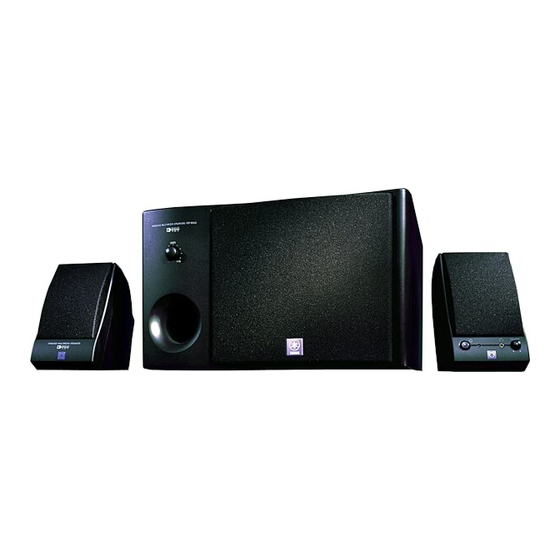
POWERED MULTIMEDIA SPEAKERS
YST-MS50/YST-MS55D
CONTENTS
TO SERVICE PERSONNEL ........................................... 1
FRONT AND REAR PANELS ..................................... 1~2
SPECIFICATIONS ....................................................... 3~4
INTERNAL VIEW ............................................................ 4
DISASSEMBLY PROCEDURES .................................... 5
USB PORT OPERATION CHECK ............................ 6~17
1 0 0 6 7 5
SERVICE MANUAL
IMPORTANT NOTICE
This manual has been provided for the use of authorized YAMAHA Retailers and their service personnel.
It has been assumed that basic service procedures inherent to the industry, and more specifically YAMAHA
Products, are already known and understood by the users, and have therefore not been restated.
WARNING:
Failure to follow appropriate service and safety procedures when servicing this product
may result in personal injury, destruction of expensive components, and failure of the
product to perform as specified. For these reasons, we advise all YAMAHA product
owners that any service required should be performed by an authorized YAMAHA
Retailer or the appointed service representative.
IMPORTANT:
The presentation or sale of this manual to any individual of firm does not constitute
authorization, certification or recognition of any applicable technical capabilities,
or establish a principle-agent relationship of any form.
The data provided is believed to be accurate and applicable to the unit(s) indicated on the cover. The research,
engineering, and service departments of YAMAHA are continually striving to improve YAMAHA products.
Modifications are, therefore, inevitable and specifications are subject to change without notice or obligation
to retrofit. Should any discrepancy appear to exist, please contact the distributor's Service Division.
WARNING:
Static discharges can destroy expensive components. Discharge any static electricity
your body may have accumulated by grounding yourself to the ground buss in the unit
(heavy gauge black wires connect to this buss).
IMPORTANT:
Turn the unit OFF during disassembly and part replacement. Recheck all work before
you apply power to the unit.
BLOCK DIAGRAM .................................................. 18~19
PRINTED CIRCUIT BOARD ................................... 20~22
IC DATA ........................................................................ 23
SCHEMATIC DIAGRAM ......................................... 24~25
PARTS LIST ............................................................ 26~37
Advertisement
Table of Contents

Related Manuals for Yamaha YST-MS50


Summary of Contents for Yamaha YST-MS50
-
Page 1: Table Of Contents
SERVICE MANUAL IMPORTANT NOTICE This manual has been provided for the use of authorized YAMAHA Retailers and their service personnel. It has been assumed that basic service procedures inherent to the industry, and more specifically YAMAHA Products, are already known and understood by the users, and have therefore not been restated. -
Page 2: To Service Personnel
YST-MS50/YST-MS55D YST-MS50 YST-MS55D TO SERVICE PERSONNEL 1. Critical Components information. Components having special characteristics are marked and must be replaced with parts having specifications equal to AC LEAKAGE WALL EQUIPMENT those originally installed. TESTER OR OUTLET UNDER TEST EQUIVALENT 2. Leakage Current Measurement (For 120V Model only). - Page 3 YST-MS50/YST-MS55D YST-MS50 YST-MS55D • Subwoofer Front Panel YST-MS55D YST-MS55D • Subwoofer Rear Panel YST-MS55D R model only YST-MS55D U and C models only B and G models A model R model U and C models...
-
Page 4: Specifications
YST-MS50/YST-MS55D YST-MS50 YST-MS55D Type Active Servo Technology (Advanced Y. S. T) Operating Section Output Power Satellite (Auto Power)Switch Satellite 20W+20W (1kHz, 4 ohms at T.H.D.=10%) Master Volume control Subwoofer 40W (100Hz, 5 ohms at T.H.D.=10%) Subwoofer Volume control Input Sencitivity... -
Page 5: Internal View
Notes: The Satellite Speakers are available by the speaker unit (Lch or Rch). Individual parts of the Satellite Speakers are not available. (See page 31 and 33 of the PARTS LIST for YST-MS50, page 34 and 36 of the PARTS LIST for YST-MS55D.) -
Page 6: Disassembly Procedures
YST-MS50/YST-MS55D YST-MS50 YST-MS55D DISASSENBLY PROCEDURES (Remove parts in disassenbly order as numbered.) • Disassemble of the Subwoofer 3. Removal of the Speaker 1. Removal of the Rear Panel Ass'y. a. Set up the front panel ass'y in the direction of the arrow, a. -
Page 7: Usb Port Operation Check
(3) Installing the YST-MS55D speaker device drivers Please follow these steps to install the Yamaha YST-MS55D speaker device drivers in your Windows 98 system using the included CD-ROM, and verify that Windows 98 recognizes the installed device drivers and that CD audio, sound generated while using software, and system sounds from the personal computer will be output via the USB port. - Page 8 YST-MS50/YST-MS55D YST-MS55D Message “Windows has found a new hardware and is locating the software for it.” appears, then: The following “Add New Hardware Wizard” appears to install the USB Composite Device. (See Fig. 1) 1. Click [Next]. Fig. 1 The system displays the following panel: (See Fig. 2) 2.
- Page 9 The system displays the following panel: (See Fig. 5) Note: Depending on your system, a path other than “D:\USB.INF” may appear. 5. Click [Next]. The system starts installing the YAMAHA YST- MS55D USB Composite Device. Please wait awhile. Fig. 5 The system displays the following panel: (See Fig.
- Page 10 The system displays a panel to begin installing a USB Audio Device. (See Fig. 9) 9. Follow the same screen instructions as steps 2–5. Make sure that “The updated driver (Recom- mended)” panel lists “YAMAHA YST-MS55D USB Audio” in step 4, and click the [Next] but- ton repeatedly until the following panel appears: Fig.
- Page 11 Open the window by the order of [My Computer], [Control Panel], [System], and click the [Device Manager] or [System Properties]. ↓ Click the [View devices by type ]. ↓ Confirm the "YAMAHA YST-MS55D USB Audio". (See Fig. 11) Confirmed. Fig. 11 ↓ To next confirmation.
- Page 12 Confirm the "Human Interface Devices". (See Fig. 12) Confirmed. Fig. 12 ↓ To next confirmation. CONFIRM 3 " YAMAHA YST-MS55D USB Composite Device " Confirm the "YAMAHA YST-MS55D USB Composite Device". (See Fig. 13) Confirmed Fig. 13 ↓ To next confirmation.
- Page 13 " YAMAHA YST-MS55D USB Audio (1) " Click the [Audio] of [Multimedia Properties]. ↓ Confirm the [Playback ]. ↓ Confirm the "YAMAHA YST-MS55D USB Audio (1) ". (See Fig. 14) Confirmed. Fig. 14 ↓ Completed the confirmation of OS. CAUTION: If not installed the YST-MS55D speaker device drivers, repeat install from the CD-ROM.
- Page 14 YST-MS50/YST-MS55D YST-MS55D 2. STARTING THE USB PORT OPERATION CHECK The USB port operation check is using the USB Compliance check Test Tool Version 2.6. Install the this Test Tool. Running the Test Tool. ↓ [PLUG IN DEVICE (S) TO TEST!] display.
- Page 15 YST-MS50/YST-MS55D YST-MS55D 3. DETAIL OF USB PORT OPERATION CHECK There are 5 items in the USB port operation check as shown below. CHECK 1 " 00Vid (0X0499) Pid (0X3001) " [USB Compliance Tool, Version 2.6] display. ↓ Confirm the " 99 Vid (0X0499) Pid (0X3001)". (See Fig. 17) Confirmed.
- Page 16 YST-MS50/YST-MS55D YST-MS55D CHECK 2 All is checked (" "). [USB Chapter 9 Test] display. ↓ Confirm that all is checked (" "). (See Fig. 18) All is checked (" "). Click. Fig. 18 ↓ Click the [Start Automated Testing ] (See Fig. 18) for next check.
- Page 17 YST-MS50/YST-MS55D YST-MS55D CHECK 3 " Error Count : 0 " [Full Test Results] display. ↓ Confirm the " Error Count : 0 ". (See Fig. 19) Confirmed. Fig. 19 ↓ Operation of between USB IC and USB port is normal state.
- Page 18 YST-MS50/YST-MS55D YST-MS55D CHECK 4 " OK " [USB Compliance Tool] display. ↓ Confirm the " OK ". (See Fig. 20) Confirmed. Fig. 20 ↓ Enter automated to next check. CHECK 5 " OK " [DEVICE IS HID] display. ↓ Confirm the " OK ". (See Fig. 21) Confirmed.
-
Page 19: Block Diagram
YST-MS50/YST-MS55D YST-MS50 YST-MS55D BLOCK DIAGRAM Rch SATELLITE SPEAKER VOLUME INPUT 1 (HEADPHONE) (NJM4556AL) Lch SATELLITE SPEAKER INPUT 2 – – –12 TWEETER RSP– TWEETER –12 SUB Wo. SUB Wo. MIDRENGE MIDRENGE – – RSP+ (AUTO POWER) LSP+ TO LEFT SPEAKER A. -
Page 20: Printed Circuit Board
YST-MS50/YST-MS55D YST-MS50 YST-MS55D PRINTED CIRCUIT BOARD (Foil side) • Subwoofer Semiconductor Location SUBWOOFER Ref. No. Location P. C. B. MAIN (6) R model only P. C. B. MAIN (7) VOUT – D201 D202 P. C. B. MAIN (3) IC201 IC202 P. -
Page 21: Printed Circuit Board
YST-MS50/YST-MS55D YST-MS50 YST-MS55D PRINTED CIRCUIT BOARD (Foil side) • Satellite Speakers P. C. B. MAIN (4) NJM4556AL Semiconductor Location Ref. No. Location VOLUME (AUTO POWER) (HEADPHONE) P. C. B. MAIN (8) P. C. B. MAIN (5) SATELLITE SATELLITE MIDRANGE MIDRANGE... -
Page 22: Ic Data
YST-MS50/YST-MS55D YST-MS55D IC DATA D– IC201: UDA1321PS Universal Serial Bus (USB) Digital-to-Analog Converter (DAC) ANALOG FRONT-END FOR ANALOG TEST VssA RTCB CONTROL BLOCK USB-PROCESSOR SHTCB GP4/BCKO GP3/WSO GP2/DO DIGITAL I/O MICRO- GP1/DI CONTROLLER GP0/BCKI GP2/DO GP1/DI GP5/WSI GP3/WSO GP4/BCKO FIFO REGISTERS... -
Page 23: Schematic Diagram
YST-MS50/YST-MS55D YST-MS55D SCHEMATIC DIAGRAM (YST-MS55D) IC201, 202/ / / / / See page 23, IC DATA USB IN USE ONLY 24.0 IC1,2,7,8 : UPC4570HA Dual OP-Amp INPUT 12.0 – – TO RIGHT VOLUME SPEAKER Vo1 –Vin1 +Vin1 V +Vin2 –Vin2 Vo2 Vcc... -
Page 24: Schematic Diagram
YST-MS50/YST-MS55D YST-MS50 SCHEMATIC DIAGRAM (YST-MS50) IC1,2,7,8 : UPC4570HA Dual OP-Amp 11.7 VOLUME – – Vo1 –Vin1 +Vin1 V +Vin2 –Vin2 Vo2 Vcc (HEAD- PHONE) -11.5 SATELLITE IC3 : NJM4556AL TWEETER Dual Op-Amp 11.7 SATELLITE MIDRANGE SATELLITE SATELLITE TWEETER MIDRANGE (AUTO POWER) –... -
Page 25: Parts List
YST-MS50/YST-MS55D WARNING P ARTS LIST Components having special characteristics are marked and must be replaced with parts having specifications equal to those originally installed. ELECTRICAL PARTS Carbon resistors (1/6W or 1/4W) are not included in the ELECTRICAL PARTS List. For the parts Nos. of the carbon resistores,refer to the last page. - Page 26 YST-MS50/YST-MS55D YST-MS50 P. C. B. MAIN Schm Schm PART NO. Description PART NO. Description V3406400 P.C.B. MAIN(UC) UM397330 C.EL 33uF V3406500 P.C.B. MAIN(R) UA653390 C.MYLAR 3900pF V3406600 P.C.B. MAIN(A) UA655180 C.MYLAR 0.18uF V3406700 P.C.B. MAIN(BG) UA653470 C.MYLAR 4700pF VB858700 CN.BS.PIN VD916400 C.EL...
- Page 27 YST-MS50/YST-MS55D YST-MS50 Schm PART NO. Description V3028000 FET 2SK304 E HV455100 R.CAR.FP 100Ω 1/4W HV455100 R.CAR.FP 100Ω 1/4W HV453470 R.CAR.FP 4.7Ω 1/4W HV453470 R.CAR.FP 4.7Ω 1/4W HV456100 R.CAR.FP 1KΩ 1/4W HV454820 R.CAR.FP 82Ω 1/4W HV453470 R.CAR.FP 4.7Ω 1/4W VE869300 R.MTL.OXD 0.1Ω...
- Page 28 YST-MS50/YST-MS55D YST-MS55D P.C.B. MAIN Schm Schm PART NO. Description PART NO. Description V3695600 P.C.B. MAIN(UC) VJ837200 C.EL 47uF V3695700 P.C.B. MAIN(R) UM397330 C.EL 33uF V3695800 P.C.B. MAIN(A) UA653390 C.MYLAR 3900pF V3695900 P.C.B. MAIN(BG) UA655180 C.MYLAR 0.18uF VB858700 CN.BS.PIN UA653470 C.MYLAR 4700pF VD005200 CN.BS.PIN...
- Page 29 YST-MS50/YST-MS55D YST-MS55D Schm Schm PART NO. Description PART NO. Description D202 VU264100 DIODE 1SR139-400 VZ496100 VR A5KΩ KB000660 FUSE 400mA 250V(ABG) XL201 V3671300 RSNR.CRYS 48MHz VT272700 FUSE 1.25A(UCR) V2572700 VOLT.SELCT (R) KB000660 FUSE 400mA 250V(R) BB070700 GND.MTL XB247301 IC uPC4570HA BB071360 SCR.TERM...
- Page 30 YST-MS50/YST-MS55D YST-MS50 EXPLODED VIEW (YST-MS50) 6-12 6-11 5-11 5-32 5-35 6-3-1 5-31 5-32 (R only) 5-17 5-12 5-33 5-34 5-15 5-20 5-16 5-21 5-15 5-19 (R only) Voltage Selector (R only) 5-18 5-14...
- Page 31 YST-MS50/YST-MS55D YST-MS50 YST-MS50 MECHANICAL PARTS (YST-MS50) Ref. Ref. Description Remarks Markets PART NO. Description Remarks Markets PART NO. V3368300 CABINET ACCESSORIES V3368400 CABINET VS494400 CABLE, MINI PLUG XV968A00 SPEAKER 16cm JA1673 VT309500 RCA PIN CABLE 1.8m 5- 1 V3406400 P.C.B. ASS’Y...
- Page 32 YST-MS50/YST-MS55D YST-MS55D YST-MS55D EXPLODED VIEW (YST-MS55D) MECHANICAL PARTS (YST-MS55D) Ref. PART NO. Description Remarks Markets V3368300 CABINET V3368400 CABINET XV968A00 SPEAKER JA1673 16cm 5- 1 V3695600 P.C.B. ASS’Y MAIN (UC) 5- 1 V3695700 P.C.B. ASS’Y MAIN 6-12 5- 1 V3695800 P.C.B. ASS’Y...
- Page 33 YST-MS50/YST-MS55D YST-MS55D Ref. PART NO. Description Remarks Markets ACCESSORIES V4368200 USB CABLE 2.0m VS494400 CABLE, MINI PLUG VT309500 RCA PIN CABLE 1.8m VZ663800 DIN PLUG CABLE 1.86m VS104300 LEG V4400400 CD-ROM V3565300 SATELLITE SPEAKER UNIT V3565700 SATELLITE SPEAKER UNIT V3566100 SATELLITE SPEAKER UNIT...
-
Page 34: Parts List For Carbon Resistors
YST-MS50/YST-MS55D Parts List for Carbon Resistors Value 1/4W Type Part No. 1/6W Type Part No. Value 1/4W Type Part No. 1/6W Type Part No. 1.0 Ω 3100 3100 10 kΩ 7100 7100 HJ35 HF85 HF45 HF45 1.8 Ω 3180 11 kΩ...