Advertisement
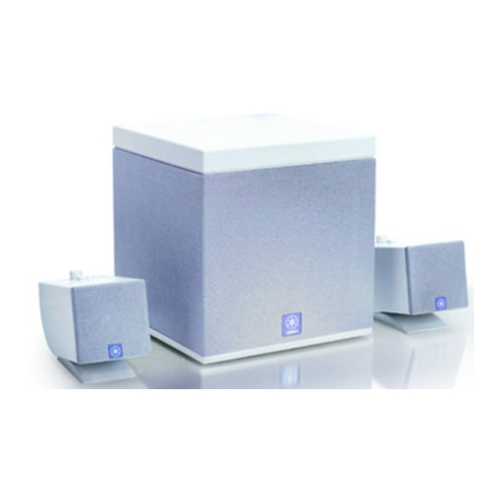
POWERED MULTIMEDIA SPEAKERS
YST-MS30/YST-MS35D
CONTENTS
TO SERVICE PERSONNEL ........................................... 1
FRONT AND REAR PANELS ..................................... 1~2
SPECIFICATIONS ....................................................... 3~4
INTERNAL VIEW ............................................................ 4
DISASSEMBLY PROCEDURES .................................... 5
1 0 0 6 9 5
SERVICE MANUAL
IMPORTANT NOTICE
This manual has been provided for the use of authorized YAMAHA Retailers and their service personnel.
It has been assumed that basic service procedures inherent to the industry, and more specifically YAMAHA
Products, are already known and understood by the users, and have therefore not been restated.
WARNING:
Failure to follow appropriate service and safety procedures when servicing this product
may result in personal injury, destruction of expensive components, and failure of the
product to perform as specified. For these reasons, we advise all YAMAHA product
owners that any service required should be performed by an authorized YAMAHA
Retailer or the appointed service representative.
IMPORTANT:
The presentation or sale of this manual to any individual of firm does not constitute
authorization, certification or recognition of any applicable technical capabilities,
or establish a principle-agent relationship of any form.
The data provided is believed to be accurate and applicable to the unit(s) indicated on the cover. The research,
engineering, and service departments of YAMAHA are continually striving to improve YAMAHA products.
Modifications are, therefore, inevitable and specifications are subject to change without notice or obligation
to retrofit. Should any discrepancy appear to exist, please contact the distributor's Service Division.
WARNING:
Static discharges can destroy expensive components. Discharge any static electricity
your body may have accumulated by grounding yourself to the ground buss in the unit
(heavy gauge black wires connect to this buss).
IMPORTANT:
Turn the unit OFF during disassembly and part replacement. Recheck all work before
you apply power to the unit.
USB PORT OPERATION CHECK TEST ................. 6~13
BLOCK DIAGRAM .................................................. 14~15
PRINTED CIRCUIT BOARD ................................... 16~17
SCHEMATIC DIAGRAM ............................................... 18
PARTS LIST ............................................................ 19~27
Advertisement
Table of Contents

Related Manuals for Yamaha YST-MS30


Summary of Contents for Yamaha YST-MS30
-
Page 1: Table Of Contents
SERVICE MANUAL IMPORTANT NOTICE This manual has been provided for the use of authorized YAMAHA Retailers and their service personnel. It has been assumed that basic service procedures inherent to the industry, and more specifically YAMAHA Products, are already known and understood by the users, and have therefore not been restated. -
Page 2: To Service Personnel
YST-MS30/YST-MS35D YST-MS30 YST-MS35D TO SERVICE PERSONNEL 1. Critical Components information. Components having special characteristics are marked must be replaced with parts having specifications equal to AC LEAKAGE WALL EQUIPMENT those originally installed. TESTER OR OUTLET UNDER TEST EQUIVALENT 2. Leakage Current Measurement (For 120V Model only). - Page 3 YST-MS30/YST-MS35D YST-MS30 YST-MS35D • Subwoofer Front YST-MS35D only Rear YST-MS35D U and C models only YST-MS35D U and C models only YST-MS35D only A model only B and G models only...
-
Page 4: Specifications
YST-MS30/YST-MS35D YST-MS30 YST-MS35D SPECIFICATIONS Type Advanced Yamaha Active Servo Technology Dimensions (W x H x D) (Advanced Y . S . T) Satellite 65x75x119mm Output Power (2.6"x3"x7-4.7") Satellite 6W+6W (1kHz, 4 ohms at T.H.D.=10%) Subwoofer 183x196x183mm Subwoofer 18W (100Hz, 4 ohms at T.H.D.=10%) (7.2"x7.7"x7.2") -
Page 5: Internal View
Notes: The Satellite Speakers are available by the speaker unit (Left or Right). Individual parts of the Satellite Speakers are not available. (See page 23 and 24 of the PARTS LIST for YST-MS30, page 25 and 26 of the PARTS LIST for YST-MS35D.) -
Page 6: Disassembly Procedures
YST-MS30/YST-MS35D YST-MS30 YST-MS35D DISASSEMBLY PROCEDURES (Remove parts in disassembly order as numbered.) • Disassemble of the Subwoofer 1. Removal of the Rear Panel Ass'y. 3. Removal of the P. C. B. Ass'y a. Remove 2 screws (3) in Fig. 3, and remove the P. C. B. -
Page 7: Usb Port Operation Check Test
1. Installing and verifying the YST-MS35D speaker device drivers Please follow these steps to install the Yamaha YST-MS35D speaker device drivers in your Windows 98 system using the included CD-ROM, and verify that Windows 98 recognizes the installed device drivers and that CD audio, sound generated while using software, and system sounds from the personal computer will be output via the USB port. - Page 8 3. Click the plus sign (+) for “Human Interface Devices,” “Sound, video and game controllers,” and “Universal Serial Bus Controller” in the device list, and check to see if “Human Interface Devices,” “YAMAHA YST-MS35D USB Audio,” and “YAMAHA YST-MS35D USB Composite Device” as shown below.
- Page 9 YST-MS30/YST-MS35D YST-MS35D (5) Re-installing the Device Driver If you connect the PC and the YST-MS35D via the USB ports using the USB cable before you install the included application software, the YST-MS35D device driver will not recognize the devices correctly, and will display the following items in the “System Properties”...
- Page 10 1. Select “Start,” then select “Settings-->Control Panel” from the menu. 2. Double-click “Multimedia” icon in the Control Panel to display the “Multimedia Properties” window, and under “Playback” in the “Audio” tab, make sure that “YAMAHA YST-MS35D USB Audio” is selected as the “Preferred device.”...
- Page 11 YST-MS30/YST-MS35D YST-MS35D 2. STARTING THE USB PORT OPERATION CHECK TEST The USB port operation check test is using the tool for check test "USB Check Version X.X". (1) Downloading the tool for check test Pease follow these steps to download the tool for check test in your PC from the homepage of "USB".
- Page 12 YST-MS30/YST-MS35D YST-MS35D 3. DETAIL OF USB PORT OPERATION CHECK TEST There are 5 items in the USB port operation check test as shown below. TEST 1 " 00Vid (0X0499) Pid (0X3002) " "USB Compliance Tool, Version 2.6" display. ↓ Confirm the " 99 Vid (0X0499) Pid (0X3002)".
- Page 13 YST-MS30/YST-MS35D YST-MS35D TEST 2 All is checked (" "). "USB Chapter 9 Test" display. ↓ Confirm that all is checked (" "). Confirmed. Click. ↓ Click the "Start Automated Testing" for next test. TEST 3 " Error Count : 0 "...
- Page 14 YST-MS30/YST-MS35D YST-MS35D TEST 4 " OK " "USB Compliance Tool" display. ↓ Confirm the " OK ". Confirmed. ↓ Enter automated to next test. TEST 5 " OK " "DEVICE IS HID" display. ↓ Confirm the " OK ". Confirmed.
-
Page 15: Block Diagram
YST-MS30/YST-MS35D YST-MS30 YST-MS35D BLOCK DIAGRAM • Subwoofer • Satellite Speaker Unit (Right) VOLUME Switch 1 IR INPUT 1 TO RIGHT SPEAKER 3 OR RSPG 4 IL INPUT 2 7 OL 5 VCC (Standby/ON) 2 E2 YST-MS35D only EEPROM USB D/A Converter... -
Page 16: Printed Circuit Board
YST-MS30/YST-MS35D YST-MS30 YST-MS35D PRINTED CIRCUIT BOARD (Foil side) • Subwoofer • Satellite Speakers Semiconductor Location Satellite Speaker Unit (Right) P.C.B. AMP(1) IC7, 8 : uPC4570HA IC6 : uPC4570HA IC2 : uPC4570HA Ref. No. Location P.C.B. AMP(3) SUBWOOFER D201 BIAS LSP+... -
Page 17: Schematic Diagram
YST-MS30/YST-MS35D YST-MS30 YST-MS35D SCHEMATIC DIAGRAM IC1~3, 6~8 : uPC4570HA Dual OP-Amp • Subwoofer AMP(2) AMP(1) H. P. F POWER AMP – – 15.1 L. P. F H. P. F Vo1 –Vin1 +Vin1 V +Vin2 –Vin2 Vo2 Vcc IC4 : TDA7370BV... -
Page 18: Parts List
YST-MS30/YST-MS35D WARNING P ARTS LIST Components having special characteristics are marked and must be replaced with parts having specifications equal to those originally installed. ELECTRICAL PARTS Carbon resistors (1/6W or 1/4W) are not included in the ELECTRICAL PARTS List. For the parts Nos. of the carbon resistores,refer to the last page. - Page 19 YST-MS30/YST-MS35D YST-MS30 Schm Schm PART NO. Description Remarks PART NO. Description Remarks AAX09900 P.C.B. 057474 XX707300 CN B09B-PH-K-S 081731 AAX09500 C.CE 1000pF 50V 051720 AAX09220 LED(gr) SLR-342MG 054160 AAX09500 C.CE 1000pF 50V 051720 iF004600 DIODE 1SS133 069460 VG287200 C.EL 10uF...
- Page 20 YST-MS30/YST-MS35D YST-MS35D Schm Schm PART NO. Description Remarks PART NO. Description Remarks AAX09920 P.C.B. 057476 C203 AAX09490 C.CE 22pF 50V 051094 AAX09500 C.CE 1000pF 50V 051720 C204 FG644100 C.CE 0.01uF 50V 065452 AAX09500 C.CE 1000pF 50V 051720 C205 AAX09970 C.CE 0.01uF 50V 049191...
- Page 21 YST-MS30/YST-MS35D YST-MS35D Schm PART NO. Description Remarks VZ229400 TR 2SC3792 068859 VZ229400 TR 2SC3792 068859 XX707330 TR 2SA733 PQ 073507 XX707340 TR 2SC945A QP 073538 XX707330 TR 2SA733 PQ 073507 AAX09180 FET 2SK304 E 051061 Q201 AAX09580 TR 2SD1200F QR 068925 HV754390 R.CAR.FP...
- Page 22 YST-MS30/YST-MS35D YST-MS30 YST-MS30 EXPLODED VIEW (YST-MS30) MECHANICAL PARTS (YST-MS30) Ref. PART NO. Description Remarks Markets AAX12660 SATELLITE SPEAKER UNIT L WH (L) 054025L AAX12680 SATELLITE SPEAKER UNIT L BL (L) 054028L AAX12670 SATELLITE SPEAKER UNIT R WH (R) 054025R AAX12690 SATELLITE SPEAKER UNIT R...
- Page 23 YST-MS30/YST-MS35D YST-MS35D YST-MS35D EXPLODED VIEW (YST-MS35D) MECHANICAL PARTS (YST-MS35D) Ref. PART NO. Description Remarks Markets AAX12700 SATELLITE SPEAKER UNIT L WH (L) 054031L AAX12720 SATELLITE SPEAKER UNIT L BL (L) 054035L AAX12710 SATELLITE SPEAKER UNIT R WH (R) 054031R AAX12730 SATELLITE SPEAKER UNIT R...
- Page 24 YST-MS30/YST-MS35D Parts List for Carbon Resistors Value 1/4W Type Part No. 1/6W Type Part No. Value 1/4W Type Part No. 1/6W Type Part No. 1.0 Ω 3100 3100 10 kΩ 7100 7100 HJ35 HF85 HF45 HF45 1.8 Ω 3180 11 kΩ...
- Page 25 YST-MS30/MS35D...