Siemens SINAMICS G120 Hardware Installation Manual
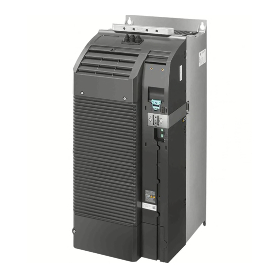
Power module
Hide thumbs
Also See for SINAMICS G120:
- List manual (1256 pages) ,
- Manual (732 pages) ,
- Operating instructions manual (550 pages)

Related Manuals for Siemens SINAMICS G120


Summary of Contents for Siemens SINAMICS G120
- Page 1 SINAMICS G120 Power Module PM240 Hardware Installation Manual · 07/2009 SINAMICS Answers for industry.
- Page 3 Introduction Safety notes Installing/Mounting SINAMICS Connecting SINAMICS G120 Power Module PM240 Service and maintenance Technical specifications Hardware Installation Manual Accessories Appendix Edition 07/2009 07/2009 A5E00807525B AD...
-
Page 4: Edition
Note the following: WARNING Siemens products may only be used for the applications described in the catalog and in the relevant technical documentation. If products and components from other manufacturers are used, these must be recommended or approved by Siemens. Proper transport, storage, installation, assembly, commissioning, operation and maintenance are required to ensure that the products operate safely and without any problems. -
Page 5: Table Of Contents
Table of contents Introduction..............................7 Safety notes............................. 13 Installing/Mounting........................... 19 Air cooling requirements ......................20 Dimensions and drill pattern ......................22 Control Unit installation ........................32 Connecting .............................. 35 Power distribution systems ......................36 Operation with ungrounded (IT) supplies..................37 Operation with Residual Current Devices (RCD).................38 Motor cable length and cross section ..................39 Access to power and motor terminals..................42 Power and motor connections .....................44... - Page 6 Table of contents Braking Resistor........................107 7.3.1 Mounting the braking resistors....................107 7.3.2 Connecting the braking resistor ....................113 7.3.3 Protecting the braking resistor ....................115 7.3.4 Technical specifications of the braking resistor ................ 116 Brake Relay..........................118 7.4.1 Mounting the Brake Relay......................118 7.4.2 Connecting the Brake Relay .....................
-
Page 7: Introduction
Introduction The SINAMICS G120 range The SINAMICS G120 inverter has been designed for the accurate and efficient control of the speed and torque for three-phase motors. The SINAMICS G120 system comprises two basic modules, the Control Unit (CU) and the Power Module (PM). - Page 8 Introduction Available Power Modules PM240 There are the following types of PM240 Power Modules with braking capacity (resistor braking). The given power rating values are defined for "high overload" operation. ● Unfiltered PM240 Power Modules 380 V … 480 V, IP20 or IPXXB, Frame size A … frame size GX, 0,37 kW … 200 kW ●...
- Page 9 Introduction Block diagram PM240, FSA … FSF Figure 1-1 Power Module PM240, frame size A … frame size F (HO 0.37 kW … 110 kW) Power Module PM240 Hardware Installation Manual, 07/2009, A5E00807525B AD...
- Page 10 Introduction Block diagram PM240, FSGX Figure 1-2 Power Module PM240, frame size GX (HO 132 kW … 200 kW) Power Module PM240 Hardware Installation Manual, 07/2009, A5E00807525B AD...
- Page 11 ● Parameter Manual ● Product Information Further internet addresses You can download the respective documents for your inverter under the following links: ● SINAMICS G110 http://www.siemens.com/sinamics-g110 ● SINAMICS G120 http://www.siemens.com/sinamics-g120 ● SINAMICS G120D http://www.siemens.com/sinamics-g120d ● SIMATIC ET 200S FC http://www.siemens.com/et200s-fc ●...
-
Page 13: Safety Notes
Safety notes Safety Instructions The following Warnings, Cautions and Notes are provided for your safety and as a means of preventing damage to the product or components in the connected machines. This section lists Warnings, Cautions and Notes, which apply generally when handling the inverter, classified as General, Transport and Storage, Commissioning, Operation, Repair and Dismantling and Disposal. - Page 14 Safety notes General WARNING This equipment contains dangerous voltages and controls potentially dangerous rotating mechanical parts. Non-compliance with the warnings or failure to follow the instructions contained in this manual can result in loss of life, severe personal injury or serious damage to property.
-
Page 15: Accessories
Safety notes CAUTION Children and the general public must be prevented from accessing or approaching the equipment! This equipment may only be used for the purpose specified by the manufacturer. Unauthorized modifications and the use of spare parts and accessories that are not sold or recommended by the manufacturer of the equipment can cause fires, electric shocks and injuries. - Page 16 Safety notes CAUTION Cable connection The control cables must be laid separately from the power cables. Carry out the connections as shown in the installation section in this manual, to prevent inductive and capacitive interference from affecting the correct function of the system. Mechanical Installation WARNING To ensure the safe operation of the equipment, it must be installed and commissioned by...
- Page 17 Safety notes Operation WARNING The inverter operates at high voltages. When operating electrical devices, it is impossible to avoid applying hazardous voltages to certain parts of the equipment. The power supply and motor terminals - and if available the DC terminals - can carry dangerous voltages even if the inverter is inoperative.
- Page 18 Safety notes Repair WARNING Repairs on equipment may only be carried out by Siemens Service, by repair centers authorized by Siemens or by authorized personnel who are thoroughly acquainted with all the warnings and operating procedures contained in this manual.
-
Page 19: Installing/Mounting
● Ensure that earthing and grounding practices for each Power Module and the cabinet follows the guidelines given in this document (Page 49) CAUTION The SINAMICS G120 Power Module MUST NOT be mounted horizontally. Power Module PM240 Hardware Installation Manual, 07/2009, A5E00807525B AD... -
Page 20: Air Cooling Requirements
Installing/Mounting 3.1 Air cooling requirements Air cooling requirements Installation and cooling Make sure that there is an adequate airflow through the cubicle as follows: 1. Add the air flow values required for every Power Module (see following table) within the cubicle 2. - Page 21 Installing/Mounting 3.1 Air cooling requirements Air cooling requirements Table 3- 1 Air cooling requirements for operation with rated power (LO) Frame LO power rating Required cooling air flow size 0.37 kW ... 1.5 kW 2.2 kW ... 4 kW 7.5 kW ... 15 kW 18.5 kW ...
-
Page 22: Dimensions And Drill Pattern
3.2 Dimensions and drill pattern Dimensions and drill pattern Dimensions, drill patterns and minimum distances The dimension drawings for all frame sizes for the SINAMICS G120 Power Module PM240 are shown in the figures and not true to scale. Figure 3-2 Dimensions and drill pattern, FSA (HO 0.37 kW ... - Page 23 Installing/Mounting 3.2 Dimensions and drill pattern Figure 3-3 Dimensions and drill pattern, FSB (HO 2.2 kW ... 4 kW) Table 3- 4 Minimum distances for mounting Minimum distances FSB Note side by 30 mm At max. environmental temperature of 40° C (104° F) and with max. HO side 1.18 inches load the Power Modules can be mounted adjacent to each other...
- Page 24 Installing/Mounting 3.2 Dimensions and drill pattern Figure 3-4 Dimensions and drill pattern, FSC (HO 5.5 kW ... 11 kW) Table 3- 5 Minimum distances for mounting Minimum distances FSC Note side by 50 mm At max. environmental temperature of 40° C (104° F) and with max. HO side 1.96 inches load the Power Modules can be mounted adjacent to each other...
- Page 25 Installing/Mounting 3.2 Dimensions and drill pattern Figure 3-5 Dimensions and drill pattern, FSD unfiltered (HO 15 kW ... 22 kW) Table 3- 6 Minimum distances for mounting Minimum distances FSD Note side by 0 mm side 0 inches above 300 mm 11.81 inches below 300 mm...
- Page 26 Installing/Mounting 3.2 Dimensions and drill pattern Figure 3-6 Dimensions and drill pattern, FSD filtered (HO 15 kW ... 22 kW) Table 3- 7 Minimum distances for mounting Minimum distances FSD Note side by 0 mm side 0 inches above 300 mm 11.81 inches below 300 mm...
- Page 27 Installing/Mounting 3.2 Dimensions and drill pattern Figure 3-7 Dimensions and drill pattern, FSE unfiltered (HO 30 kW ... 37 kW) Table 3- 8 Minimum distances for mounting Minimum distances FSE Note side by 0 mm side 0 inches above 300 mm 11.81 inches below 300 mm...
- Page 28 Installing/Mounting 3.2 Dimensions and drill pattern Figure 3-8 Dimensions and drill pattern, FSE filtered (HO 30 kW ... 37 kW) Table 3- 9 Minimum distances for mounting Minimum distances FSE Note side by 0 mm side 0 inches above 300 mm 11.81 inches below 300 mm...
- Page 29 Installing/Mounting 3.2 Dimensions and drill pattern Figure 3-9 Dimensions and drill pattern, FSF unfiltered (HO 45 kW ... 110 kW) Table 3- 10 Minimum distances for mounting Minimum distances FSF Note side by 0 mm side 0 inches above 350 mm 13.77 inches below 350 mm...
- Page 30 Installing/Mounting 3.2 Dimensions and drill pattern Figure 3-10 Dimensions and drill pattern, FSF filtered (HO 45 kW ... 110 kW) Table 3- 11 Minimum distances for mounting Minimum distances FSF Note side by 0 mm side 0 inches above 350 mm 13.77 inches below 350 mm...
- Page 31 Installing/Mounting 3.2 Dimensions and drill pattern Figure 3-11 Dimensions and drill pattern, FSGX (HO 132 kW ... 200 kW) Table 3- 12 Minimum distances for mounting Minimum distances FSGX Note side by 0 mm side 0 inches above 250 mm 9.84 inches below 150 mm...
-
Page 32: Control Unit Installation
Installing/Mounting 3.3 Control Unit installation Control Unit installation Fitting the CU to the PM FSA ... FSF The Control Unit is snapped onto the Power Module as shown in the figure below. To disconnect the CU push the release button on top of the PM. The process of fitting the Control Unit to the Power Module is the same technique independent from the type of Control Unit or Power Module. - Page 33 Installing/Mounting 3.3 Control Unit installation Fitting the CU to the Power Module FSGX The Control Unit is snapped inside the Power Module housing behind the front plate. 1. Unscrew the two fixing screws at the bottom of the front cover. 2.
- Page 34 Installing/Mounting 3.3 Control Unit installation Adapting the CU frame of the Power Module front cover A plastic frame in the front cover of the Power Module ensures the IP20 or IPXXB protection class of the inverter. This plastic frame has to be adapted to the Control Unit: ●...
-
Page 35: Connecting
Connecting Electrical Installation WARNING Power and motor connections A fixed location, non varying connection is necessary because of a leakage current > 3.5 mA. The inverter must always be grounded. If it is not grounded correctly, extremely dangerous conditions may arise which could prove potentially fatal. Isolate the mains electrical supply before making or changing connections to the unit. -
Page 36: Power Distribution Systems
Connecting 4.1 Power distribution systems Power distribution systems Overview of Power Distribution Systems The power distribution systems described below, as defined in EN 60950 , have been considered in the design of the inverter. In the next figures three phase systems are outlined. The three phase inverter must be connected to L1, L2 and L3. -
Page 37: Operation With Ungrounded (It) Supplies
Connecting 4.2 Operation with ungrounded (IT) supplies Operation with ungrounded (IT) supplies Operation with ungrounded (IT) supplies IT supplies are fully isolated from the protective earth system, usually by an isolating transformer. It should be noted, however, that a protective earth is still provided. WARNING Power Modules with built-in filters or external filters must not be used with IT supplies. -
Page 38: Operation With Residual Current Devices (Rcd)
Connecting 4.3 Operation with Residual Current Devices (RCD) Operation with Residual Current Devices (RCD) Operation with Residual Current Devices (RCD) If an RCD (also referred to as an ELCB or a RCCB) is fitted, the Power Module will operate without nuisance tripping provided that: ●... -
Page 39: Motor Cable Length And Cross Section
Connecting 4.4 Motor cable length and cross section Motor cable length and cross section Permissible Cable Length The use of unshielded motor cables is possible. However to meet C2 EMI class, shielded cables with appropriate EMI installation are required. Table 4- 2 The inverters will operate at full specification with cable lengths as follows •... - Page 40 Connecting 4.4 Motor cable length and cross section Table 4- 4 Cable cross section Frame size Cable cross section Tightening torques lbf in 0.37: 1.0 … 2.5 18 … 14 0.55: 1.0 … 2.5 18 … 14 0.75: 1.0 … 2.5 18 …...
- Page 41 Connecting 4.4 Motor cable length and cross section CAUTION Cable cross section for grounding For power cables up to 10 mm² (Cu) or 16 mm² (Al) the earth cable must be at least as big as the power cables. For power cables larger than 10 mm² (Cu) or 16 mm² (Al) the earth cable must be at least 10 mm²...
-
Page 42: Access To Power And Motor Terminals
Connecting 4.5 Access to power and motor terminals Access to power and motor terminals Accessing the power and motor terminals Frame sizes A … C have no terminal covers. Frame sizes D … F terminal covers are accessed by the following steps, as shown in the figure below: 1. - Page 43 Connecting 4.5 Access to power and motor terminals The terminals of FSGX are accessed by removing the front cover: 1. Unscrew the two fixing screws at the bottom of the front cover 2. Push the cover upwards and remove it Power Module PM240 Hardware Installation Manual, 07/2009, A5E00807525B AD...
-
Page 44: Power And Motor Connections
Connecting 4.6 Power and motor connections Power and motor connections Power and motor terminal layout The figures below show the layout of the power and motor terminals of the Power Module. The figure also includes the tightening torques for the terminals. Figure 4-2 Power and motor terminal layout for the FSA ... - Page 45 Connecting 4.6 Power and motor connections Figure 4-3 Power and motor terminal layout for the FSGX M10 tightening torque: 25 Nm/18.4 lbf.ft Power Module PM240 Hardware Installation Manual, 07/2009, A5E00807525B AD...
-
Page 46: Dc 24V Power Supply Connection (Fsgx)
Connecting 4.7 DC 24V power supply connection (FSGX) DC 24V power supply connection (FSGX) -X9: Terminal block The Power Module FSGX requires a separate DC 24V power supply. The power supply is connected to the X9 terminal block of the Power Module. Figure 4-4 -X9 terminal block ①... -
Page 47: Adjusting The Fan Voltage (Fsgx)
Connecting 4.8 Adjusting the fan voltage (FSGX) Adjusting the fan voltage (FSGX) Fine-tuning the supply voltage of the fan The power supply for the device fan (1 AC 230 V) in the Power Module is generated from the line supply using a transformer. The transformer is fitted with primary taps so that it can be fine-tuned to the supply voltage. -
Page 48: Line Contactor Control (Fsgx)
Connecting 4.9 Line contactor control (FSGX) Line contactor control (FSGX) -X9: Terminal block The Power Module FSGX can control its line contactor. The control terminals for the line contactor are on the terminal block -X9. Figure 4-6 -X9 terminal block ① on the Power Module FSGX Table 4- 7 Terminal block -X9 Terminal... -
Page 49: Esd Guidelines
For all frame sizes the Screen Termination Kit is supplied as an optional extra. It allows easy and efficient connection of the necessary screening. For further details on the Screen Termination Kit, please refer to the SINAMICS G120 catalog. Power Module PM240... - Page 50 Connecting 4.10 ESD guidelines Screening without a Screen Termination Kit In order to meet radiated emissions a screen termination kit must be used. Screening without a screen termination kit is only suitable for installation in a metal cabinet. Should a Screen Termination Kit not be available, the inverter then can be screened using the methodology shown in the figure below.
-
Page 51: Service And Maintenance
The actual intervals at which maintenance procedures are to be performed depend on the installation conditions and the operating conditions. Siemens offers its customers support in the form of a service contract. For further details, contact your regional office or sales office. -
Page 52: Replacing Components
Service and maintenance 5.2 Replacing components Replacing components Power Module spare parts Spare part available (✓) or not available (-) for Power Module ... FSGX 0.37 kW 2.2 kW 5.5 kW 15 kW 30 kW 45 kW 132 kW 1.5 kW 4 kW 11 kW 22 kW... -
Page 53: Replacing The Cooling Fan
Service and maintenance 5.2 Replacing components 5.2.1 Replacing the cooling fan The service life of the cooling fan The average service life of the cooling fans is 50,000 hours. In practice, however, the service life may deviate from this value. Especially a dusty environment can occlude the fan. The fan must be replaced in good time to ensure that the inverter is available. - Page 54 Service and maintenance 5.2 Replacing components Cooling fan replacement for FSD … FSF Preparatory steps ● Power-down the inverter ● Remove the Control Unit from the inverter ● Disconnect all the cables from the Power Module ● Place the Power Module face-down on a clean and safe surface Removal 1.
- Page 55 Service and maintenance 5.2 Replacing components Replacing the cooling fan FSGX Preparatory steps ● Disconnect the chassis unit from the power supply. ● Allow unimpeded access. ● Remove the protective cover. Figure 5-4 Fan replacement, Power Module FSGX Power Module PM240 Hardware Installation Manual, 07/2009, A5E00807525B AD...
-
Page 56: Replacing The Cooling Fan Fuses And The Cooling Fan Relay (Fsgx)
Service and maintenance 5.2 Replacing components Removal The steps for the removal procedure are numbered in accordance with the diagram. 1. Remove the retaining screws for the fan (3 screws). 2. Disconnect the supply cables (1 x "L", 1 x "N"). You can now carefully remove the fan. -
Page 57: Power Block Replacement (Fsgx)
Service and maintenance 5.2 Replacing components 5.2.3 Power block replacement (FSGX) Figure 5-6 Power block replacement, PM240 FSGX Power Module PM240 Hardware Installation Manual, 07/2009, A5E00807525B AD... - Page 58 Service and maintenance 5.2 Replacing components Preparatory steps ● Disconnect the built-in unit from the power supply. ● Allow unimpeded access to the power block. ● Remove the protective cover. Removal The steps for the removal procedure are numbered in accordance with the diagram. 1.
- Page 59 Service and maintenance 5.2 Replacing components Crane lifting lugs for secure transportation of the power block The power blocks are fitted with crane lifting lugs for transportation on a lifting harness in the context of replacement. The positions of the crane lifting lugs are illustrated by arrows in the figures below. WARNING A lifting harness with vertical ropes or chains must be used to prevent any risk of damage to the housing.
- Page 60 Service and maintenance 5.2 Replacing components Figure 5-7 Crane lifting lugs of the Power Block FSGX Power Module PM240 Hardware Installation Manual, 07/2009, A5E00807525B AD...
-
Page 61: Control Interface Module Replacement (Fsgx)
Service and maintenance 5.2 Replacing components 5.2.4 Control Interface Module replacement (FSGX) Figure 5-8 Control Interface Module replacement, Power Module PM240 FSGX Power Module PM240 Hardware Installation Manual, 07/2009, A5E00807525B AD... - Page 62 Service and maintenance 5.2 Replacing components Preparatory steps ● Disconnect the Power Module from the power supply. ● Allow unimpeded access. ● Remove the front cover. ● Remove the Control Unit. If necessary, remove the communication plugs and terminal wiring. Removal The steps for the removal procedure are numbered in accordance with the diagram.
- Page 63 Service and maintenance 5.2 Replacing components CAUTION The connectors of the fiber-optic cables have to be mounted on their original plug-in position. The fiber-optic cables and the plug sockets are labelled accordingly (U11, U21, U31). Carefully re-establish the plug connections and ensure that they are secure. When dealing with connectors with a lock, make sure that the locking lever is securely engaged once connected.
-
Page 65: Technical Specifications
Technical specifications Common performance ratings of the Power Module Table 6- 1 Performance ratings Feature Specification Line operating voltage 3 AC 380 V … 480 V ± 10% The permissible voltage depends on the operational altitude Input frequency 47 Hz … 63 Hz Power factor λ... - Page 66 Shock and vibration Do not drop the SINAMICS G120 or expose to sudden shock. Do not install the SINAMICS G120 in an area where it is likely to be exposed to constant vibration. Electromagnetic radiation Do not install the SINAMICS G120 near sources of electromagnetic radiation.
- Page 67 Technical specifications Relationship between pulse frequency and output base-load current reduction Table 6- 2 Current reduction depending on pulse frequency LO base Output base-load current at pulse frequency of load 2 kHz 4 kHz 6 kHz 8 kHz 10 kHz 12 kHz 14 kHz 16 kHz...
- Page 68 Technical specifications Operating temperature derating The operating temperature range is shown diagramatically in the figures below: Permissible output base load current [%] Permissible output base load current [%] High overload (HO) Light overload (LO) Ambient operating temperature [°C] Ambient operating temperature [°C] Figure 6-1 Current derating for temperature, FSA …...
- Page 69 Technical specifications Operational altitude derating The figures below show the derating required according to altitude. Permissible output base load current [%] Permissible output base load current [%] High overload (HO ) and light overload (LO) High overload (HO) and light overload (LO) 1000 2000 3000...
- Page 70 Technical specifications Power Module specifications CAUTION High Overload (HO) and Light Overload (LO) input currents The input current at the rated operating point - applies for the short-circuit voltage of the line supply V = 1% referred to the rated Power Module power and a rated line supply voltage of 400 V without a line reactor.
- Page 71 Technical specifications Table 6- 4 Frame Sizes A, 3 AC 380 V … 480 V, ± 10% Order No. unfiltered 6SL3224- 0BE21-1UA0 0BE21-5UA0 Rated power based on HO- loading Power loss 0.108 0.114 Rated input current (HO) Rated output current (HO) Rated input current (LO) Rated output current (LO) Fuse...
- Page 72 Technical specifications Table 6- 6 Frame Sizes C, 3 AC 380 V … 480 V, ± 10% Order No. filtered 6SL3224- 0BE25-5AA0 0BE27-5AA0 0BE31-1AA0 unfiltered 0BE25-5UA0 0BE27-5UA0 0BE31-1UA0 Rated power based on HO- loading Power loss 0.240 0.297 0.396 Rated input current (HO) 16.7 23.7 32.7...
- Page 73 Technical specifications Table 6- 8 Frame Sizes E, 3 AC 380 V … 480 V, ± 10% Order No. filtered 6SL3224- 0BE33-0AA0 0BE33-7AA0 unfiltered 0BE33-0UA0 0BE33-7UA0 Rated power based on HO- loading Power loss filtered 1.04 unfiltered 0.99 Rated input current (HO) Rated output current (HO) Rated input current (LO) Rated output current (LO)
- Page 74 Technical specifications Table 6- 10 Frame Sizes F, 3 AC 380 V … 480 V, ± 10% Order No. unfiltered 6SL3224- 0BE38-8UA0 0BE41-1UA0 Rated power based on HO- loading Power loss Rated input current (HO) Rated output current (HO) Rated input current (LO) Rated output current (LO) Fuse Required cooling air flow...
-
Page 75: Accessories
Accessories Which accessory is available for which Power Module? Accessory available (✓) or not available (-) for Power Module … FSGX 0.37 k 2.2 kW 5.5 kW 15 kW 30 kW 45 kW 132 kW 4 kW 11 kW 22 kW 37 kW 110 kW 200 kW... -
Page 76: Reactor And Filter
Accessories 7.1 Reactor and filter Reactor and filter Line reactor The purpose of a line reactor is to reduce line-side harmonic currents and harmonic effects. This applies particularly in the case of weak power supplies (network short-circuit power uK > 1 %). Line filter The Power Module complies with a higher radio interference class when an additional line filter is used. - Page 77 Accessories 7.1 Reactor and filter Connecting reactor and filter to the Power Module The following drawings show the connecting order of the power components. Shielded cables are necessary if a line filter (external or integrated) is used. Line fuses and contactor have to be installed between line reactor input and mains system. L1’...
- Page 78 Accessories 7.1 Reactor and filter Mounting base components Many system components for the Power Modules are designed as base components, that is, the component is mounted on the cabinet wall and the Power Module above it in a space- saving construction. Up to two base components can be mounted above one another. Every further system component has to be mounted laterally.
-
Page 79: Line Reactor
Figure 7-2 Connecting the line reactor as base component The overall and mounting dimensions of the line reactor are written in the technical specifications. For more information see http://support.automation.siemens.com/WW/view/en/23623183 Power Module PM240 Hardware Installation Manual, 07/2009, A5E00807525B AD... - Page 80 Accessories 7.1 Reactor and filter Installing the line reactor as lateral mounting component The line reactors for PM240 Power Modules of frame sizes FSF and FSGX (45 kW … 200 kW) have to be mounted laterally. Figure 7-3 Connecting the line reactor as lateral mounting component Technical specifications of the line reactors The major electrical specification of the line reactors is the same as for the suitable Power Module.
- Page 81 Accessories 7.1 Reactor and filter Table 7- 2 Technical specifications of the line reactors (table 1 of 6) Feature Suitable for Power Module with rated power (HO) of 0.37 kW ... 0.55 kW 0.75 kW ... 1.1 kW 1.5 kW MLFB of the line reactor 6SE6400-3CC00-2AD3 6SE6400-3CC00-4AD3...
- Page 82 Accessories 7.1 Reactor and filter Feature Suitable for Power Module with rated power (HO) of 2.2 kW ... 3 kW 4 kW 5.5 kW ... 7.5 kW Fixing dimensions Width 120 mm 156 mm Height 200 mm 232 mm Fixing screw 4 ×...
- Page 83 Accessories 7.1 Reactor and filter Table 7- 5 Technical specifications of the line rectors (table 4 of 6) Feature Suitable for Power Module with rated power (HO) of 30 kW ... 37 kW MLFB of the line reactor 6SL3203-0CJ28-6AA0 MLFB of the suitable Power 6SL3224-0BE33-0 .
- Page 84 Accessories 7.1 Reactor and filter Feature Suitable for Power Module with rated power (HO) of 45 kW ... 55 kW 75 kW 90 kW Fixing dimensions Width 95 mm 101 mm Depth 185 mm 200 mm Fixing screw 4 × M8 Weight 25 kg 24 kg...
-
Page 85: Line Filter
Accessories 7.1 Reactor and filter 7.1.2 Line filter Installing the line filter as base component The line filters associated with the Power Modules of a rated power (HO) up to 11 kW are designed as base components. The line filter is attached to the mounting surface and the Power Module is mounted directly on the line filter. - Page 86 Accessories 7.1 Reactor and filter Installing the line filter as lateral mounting component The line filters for Power Modules with a rated power (HO) of more than 11 kW and line filters from third party suppliers have to be mounted laterally. L1’...
- Page 87 Accessories 7.1 Reactor and filter Table 7- 8 Technical specifications of the line filters class A Feature Suitable for Power Module with rated power (HO) of 0.37 kW ... 1.5 kW 90 kW ... 110 kW 132 kW ... 200 kW FSGX MLFB of the line filter 6SE6400-2FA00-6AD0...
- Page 88 Accessories 7.1 Reactor and filter Feature Suitable for Power Module with rated power (HO) of 0.37 kW ... 1.5 kW 2.2 kW ... 4 kW 5.5 kW ... 11 kW Overall dimensions Width 73 mm 153 mm 190 mm Height 200 mm 296 mm 362 mm...
-
Page 89: Output Reactor
Accessories 7.1 Reactor and filter 7.1.3 Output reactor Installing the output reactor as base component The output reactors for Power Modules with a rated power (HO) up to 11 kW are designed as base components. The output reactor is attached to the mounting surface and the Power Module is mounted directly on the output reactor. - Page 90 Figure 7-7 Connecting the output reactor as lateral component For more information see http://support.automation.siemens.com/WW/view/en/22103628 Technical specifications of the output reactors The major electrical specification of the output reactors is the same as for the suitable Power Module. This applies to: ●...
- Page 91 Accessories 7.1 Reactor and filter Table 7- 10 Technical specifications of the output reactors (table 1 of 6) Feature Suitable for Power Module with rated power (HO) of 0.37 kW ... 1.5 kW 2.2 kW … 4 kW 5.5 kW … 11 kW MLFB of the line reactor 6SE6400-3TC00-4AD2 6SL3202-0AE21-0CA0...
- Page 92 Accessories 7.1 Reactor and filter Feature Suitable for Power Module with rated power (HO) of 15 kW 18.5 kW 22 kW Fixing dimensions Width 70 mm 94 mm 70 mm Height 176 mm 176 mm 176 mm Fixing screw 4 × M6 Weight 10.5 kg 16 kg...
- Page 93 Accessories 7.1 Reactor and filter Table 7- 13 Technical specifications of the output reactors (table 4 of 6) Feature Suitable for Power Module with rated power (HO) of 55 kW 75 kW 90 kW MLFB of the line reactor 6SE6400-3TC15-4FD0 6SE6400-3TC14-5FD0 6SL3000-2BE32-1AA0 MLFB of the suitable Power...
- Page 94 Accessories 7.1 Reactor and filter Feature Suitable for Power Module with rated power (HO) of 110 kW 132 kW 160 kW FSGX Fixing screw 4 × M8 Weight 52 kg 66 kg 73 kg Possible as base component Table 7- 15 Technical specifications of the output reactors (table 6 of 6) Feature Suitable for Power Module with rated power (HO) of...
-
Page 95: Sine-Wave Filter
Accessories 7.1 Reactor and filter 7.1.4 Sine-wave filter Installing the sine-wave filter as base component The sine-wave filters for Power Modules with a rated power (HO) up to 11 kW are designed as base components. The sine-wave filter is attached to the mounting surface and the Power Module is mounted directly on the sine-wave filter. - Page 96 Figure 7-9 Connecting the sine-wave filter as lateral component For more information see http://support.automation.siemens.com/WW/view/en/29522775 Technical specifications of the sine-wave filter The major electrical specification of the sine-wave filter is the same as for the suitable Power Module. This applies to: ●...
- Page 97 Accessories 7.1 Reactor and filter Table 7- 16 Technical specifications of the sine-wave filters (table 1 of 5) Feature Suitable for Power Module with rated power (HO) of 0.37 kW ... 0.75 kW 1.1 kW … 1.5 kW 2.2 kW …3 kW MLFB of the sine-wave 6SL3202-0AE20-3SA0 6SL3202-0AE20-6SA0...
- Page 98 Accessories 7.1 Reactor and filter Feature Suitable for Power Module with rated power (HO) of 4 kW 5.5 kW 7.5 kW … 11 kW Overall dimensions Width 153 mm 189 mm Height 270 mm 336 mm Depth 100 mm 140 mm Installation clearance 100 mm Bottom...
- Page 99 Accessories 7.1 Reactor and filter Feature Suitable for Power Module with rated power (HO) of 15 kW … 18.5 kW 22 kW 30 kW … 37 kW Weight 24 kg 34 kg 45 kg Possible as base component Table 7- 19 Technical specifications of the sine-wave filters (table 4 of 5) Feature Suitable for Power Module with rated power (HO) of...
- Page 100 Accessories 7.1 Reactor and filter Table 7- 20 Technical specifications of the sine-wave filters (table 5 of 5) Feature Suitable for Power Module with rated power (HO) of 132 kW 160 kW 200 kW FSGX MLFB of the sine-wave 6SL3000-2CE32-8AA0 6SL3000-2CE33-3AA0 6SL3000-2CE34-1AA0 filter...
-
Page 101: Brake Chopper (Fsgx)
Accessories 7.2 Brake chopper (FSGX) Brake chopper (FSGX) The function of the brake chopper The brake chopper controls the external braking resistor. ● The brake chopper is integrated in the Power Module FSA … FSF ● The Power Module FSGX does not contain a brake chopper. The brake chopper is available as an accessory only for the Power Module FSGX Figure 7-10 Brake chopper for Power Module FSGX... -
Page 102: Installing The Brake Chopper (Fsgx)
Accessories 7.2 Brake chopper (FSGX) 7.2.1 Installing the Brake chopper (FSGX) The brake chopper is installed in a slot within the Power Module FSGX and force-cooled by its fan. The brake chopper is connected to the DC link by means of flexible cables, which are supplied as standard. - Page 103 Accessories 7.2 Brake chopper (FSGX) Figure 7-12 Installing the brake chopper in a Power Module FSGX – steps 4 - 6 Installing the brake chopper The steps for the installation procedure are numbered in accordance with the figures in the diagrams.
-
Page 104: Connecting The Brake Chopper To The Pm
Accessories 7.2 Brake chopper (FSGX) 6. Secure the connecting cable to the DC link with 2 screws (brake chopper connection) and 2 nuts (DC link connection). Carry out the subsequent steps in reverse order from steps 1 – 3. An opening above the connections for the braking resistor (R1, R2) is provided in the cover for connecting the cable to the braking resistor. - Page 105 Accessories 7.2 Brake chopper (FSGX) Connection overview Figure 7-13 Connection overview of the brake chopper Digital input and output The connection of the digital input and output is not required for the function of the brake chopper. Table 7- 21 Terminal block X21 Terminal Designation...
- Page 106 Accessories 7.2 Brake chopper (FSGX) Threshold switch The response threshold at which the brake chopper is activated and the DC link voltage generated during braking are specified in the following table. WARNING The threshold switch must only be used when the Power Module is switched off and the DC link capacitors are discharged.
-
Page 107: Braking Resistor
Braking Resistor Braking resistor The braking resistor is designed for the SINAMICS G120 inverters with an internal brake chopper and enables loads with a large moment of inertia to be braked quickly. During braking of the motor and the load, excess energy is fed back to the inverter. This causes the voltage to rise in the DC link. - Page 108 Accessories 7.3 Braking Resistor Braking resistor for Power Modules FSA and FSB (0.37 kW … 4 kW) Figure 7-14 Dimensions of the braking resistor, FSA and FSB Power Module PM240 Hardware Installation Manual, 07/2009, A5E00807525B AD...
- Page 109 Accessories 7.3 Braking Resistor Table 7- 23 Dimension data: Braking resistor, all data in mm and (inches) Order No. of the braking resistor 6SE6400-4BD11-0AA0 6SL3201-0BE12-0AA0 Suitable for Power Module (HO) 0.37 kW ... 1.5 kW 2.2 kW ... 4 kW Order-No.
- Page 110 Accessories 7.3 Braking Resistor Braking resistor for Power Modules FSC … FSF (5.5 kW … 110 kW) Figure 7-15 Dimensions of the braking resistors, FSC ... FSF Power Module PM240 Hardware Installation Manual, 07/2009, A5E00807525B AD...
- Page 111 Accessories 7.3 Braking Resistor Table 7- 24 Dimension data: Braking resistor, all data in mm and (inches), Part 1 Order No. of the braking 6SE6400-4BD16- 6SE6400-4BD21- 6SE6400-4BD22- resistor 5CA0 2DA0 2EA0 Suitable for Power Module (HO) 5.5 kW ... 11 kW 15 kW ...
- Page 112 Accessories 7.3 Braking Resistor Braking resistor for Power Module FSGX (132 kW … 200 kW) Figure 7-16 Dimensions of the braking resistor FSGX, order-no. 6SL3000-1BE32-5AA0 CAUTION A ventilation clearance of 200 m must be maintained on all sides of the braking resistor (with ventilation grilles).
-
Page 113: Connecting The Braking Resistor
Accessories 7.3 Braking Resistor 7.3.2 Connecting the braking resistor The braking resistor is connected at terminals DCP/R1 and R2. FSA ... FSF: The braking resistor can be connected directly to the Power Module. FSGX: The connecting of a braking resistor requires the installation of a brake chopper. - Page 114 Accessories 7.3 Braking Resistor Figure 7-19 PM240 FSC spades Note With the cutout cover removed and no connections fitted to the spades, the inverter has only IP00 protection. Power Module PM240 Hardware Installation Manual, 07/2009, A5E00807525B AD...
-
Page 115: Protecting The Braking Resistor
1. Connect the thermostatic switch to a free digital input of the SINAMICS G120 so that the converter is disconnected from the power supply if the braking resistor overheats. -
Page 116: Technical Specifications Of The Braking Resistor
Accessories 7.3 Braking Resistor 2. Establish the power supply to the Power Module through a contactor which then shuts down the power supply when the resistor overheats. The thermostatic switch is connected in series with the coil feeder cable for the main contactor. The contacts of the thermostatic switch close again as soon as the resistor temperature has fallen below the selected value. - Page 117 Accessories 7.3 Braking Resistor Resistor for Power Module ... FSA Nominal power (HO) of the 0.37 kW ... 2.2 kW ... 4 kW 5.5 kW ... 15 kW ... 22 kW Power Module 1.5 kW 11 kW Order number 6SE6400- 6SE6400- 6SE6400- 6SE6400-...
-
Page 118: Brake Relay
Mounting the Brake Relay on Power Module FSA … FSF The Brake Relay can be panel mounted, wall mounted or mounted on the screen termination kit. For more information see http://support.automation.siemens.com/WW/view/en/23623179 Power Module PM240 Hardware Installation Manual, 07/2009, A5E00807525B AD... - Page 119 Accessories 7.4 Brake Relay Mounting the Brake Relay on Power Module FSGX The Brake Relay has to be mounted on the bracket above the Control Unit. 1. Mount the Brake Relay to the Control Unit bracket. 2. Connect the Brake Relay and the Power Module via the flying lead. 3.
-
Page 120: Connecting The Brake Relay
Accessories 7.4 Brake Relay 7.4.2 Connecting the Brake Relay Connecting the Brake Relay to the Power Module Connect one end of the cable form to the Brake Relay. Two cable form with different lengths are provided with the Brake Relay. Choice the adequate length of the cable depending on the frame size of the Power Module and on the mounting location of the Brake Relay. - Page 121 Accessories 7.4 Brake Relay Connecting the Brake Relay to the motor brake Figure 7-23 Brake Relay connection The Brake Relay has to be connected to protective earth, if the motor brake is supplied by a PELV circuit. Connecting the Safe Brake Relay to the motor brake The Safe Brake Relay can only control motor brakes with 24V power supply.
-
Page 122: Technical Specifications Of The Brake Relay
Accessories 7.4 Brake Relay 7.4.3 Technical specifications of the Brake Relay Brake Relay specifications Brake Relay Safe Brake Relay Input voltage connected to the internal power DC 20.4 ... 28.8 V 1) supply of the Power Module Input current Max. 2.5 A Max. -
Page 123: Din Rail Mounting Kit
DIN rail mounting kit Function The DIN rail mounting kit (DRMK) is designed to allow the SINAMICS G120 FSA and FSB inverters to be mounted on a pair of parallel DIN rails. The DRMK provides an integrated screening plate to allow for the termination of the screened motor cables and other screened cable used with the inverter. -
Page 125: Appendix
European government organization. This approach allows the use of standards that are still in preparation. EMC Standards The SINAMICS G120 drives have been tested in accordance with the EMC Product Standard EN 61800-3:2004. Power Module PM240 Hardware Installation Manual, 07/2009, A5E00807525B AD... -
Page 126: Definition Of The Emc Environment And Categories
Appendix A.2 Definition of the EMC Environment and Categories Definition of the EMC Environment and Categories Classification of EMC performance The EMC environment and categories are defined within the EMC Product Standard EN 61800-3, as follows: First Environment An environment that includes domestic premises and establishments that are connected directly to a public low-voltage power supply network without the use of an intermediate transformer. - Page 127 All drives should be installed and commissioned in accordance with the manufacturer’s guidelines and in accordance with good EMC practices. For further information refer to SIEMENS application note "EMC Design Guidelines". Power Module PM240 Hardware Installation Manual, 07/2009, A5E00807525B AD...
-
Page 128: Emc Overall Performance
Appendix A.3 EMC Overall Performance EMC Overall Performance EMC Emissions The SINAMICS G120 drives have been tested in accordance with the emission requirements of the category C2 (domestic) environment. Table A- 2 Conducted & Radiated Emissions EMC Phenomenon Standard Level... - Page 129 Appendix A.3 EMC Overall Performance EMC Immunity The SINAMICS G120 drives have been tested in accordance with the immunity requirements of category C3 (industrial) environment: Table A- 4 EMC Immunity EMC Phenomenon Standard Level Performance Criterion Electrostatic Discharge (ESD) EN 61000-4-2...
-
Page 130: Standards
EN 60204-1 — Safety of machinery –Electrical equipment of machines European Machinery Directive The SINAMICS G120 inverter series does not fall under the scope of the Machinery Directive. However, the products have been fully evaluated for compliance with the essential Health & Safety requirements of the directive when used in a typical machine application. -
Page 131: Abbreviations
Appendix A.5 Abbreviations Abbreviations Abbreviation State Alternating Current Communauté Européenne Control Unit Direct current Digital input DIP switch Digital output Equivalent circuit diagram European Economic Community ELCB Earth leakage circuit breaker Electromagnetic compatibility Electromagnetic interference Frame size A Frame size B Frame size C Frame size D Frame size E... -
Page 133: Index
Index DIN rail mounting kit, 121 Drill pattern, 22 Accessing the power and motor terminals, 41 Air barrier, 20 Air cooling requirements, 21 Earth cable, 40 Air flow, 20 Electrical installation, 16, 35 Air short circuit, 20 Electromagnetic compatibility, 123 Electromagnetic Interference (EMI), 48 EMC Emissions, 126 EMC Standards, 123... - Page 134 Second Environment, 124 side by side, 22 Self certification, 123 Service life of the fan, 52 Signal connections, 45, 47 SINAMICS G120 range, 7 Operating temperature, 67 Sine-wave filter, 39 Operation with Residual Current Devices (RCD), 38 Installing, 76, 78, 94...
- Page 135 Index Technical construction file, 123 Technical specifications Brake Relay, 119 Braking resistor, 114 Line filter, 86 Line reactor, 80 Output reactor, 89 Power Module, 65 Sine-wave filter, 95 Temperature rise, 20 Terminal cover, 41 Tightening torque, 22, 43 TN-C, 36 TN-C-S, 36 TN-S, 36 TT, 36...
- Page 136 Siemens AG Subject to change without notice Industry Sector © Siemens AG 2009 Drive Technologies Standard Drives Postfach 3180 91050 ERLANGEN GERMANY www.siemens.com/sinamics-g120...