Delta Solivia 2.5 Operation And Installation Manual
Hide thumbs
Also See for Solivia 2.5:
- Operation and installation manua (392 pages) ,
- Operation and installation manual (148 pages)
Table of Contents
Advertisement
Advertisement
Table of Contents

Related Manuals for Delta Solivia 2.5


Summary of Contents for Delta Solivia 2.5
- Page 1 Operation and installation manual...
-
Page 3: Table Of Contents
Table of Contents Scope of delivery General warnings / Notes on safety Introduction System 4.1 Data evaluation and communication 4.2 Technical structure of the solar inverter 4.3 Equipment overview Installation Installation of equipment 6.1 Installation location 6.2 Minimum requirements 6.3 Maintenance 6.4 Installation 6.5 Ambient temperature 6.6 Grid connection 6.7 Connection of PV modules 6.7.1 Output power over PV voltage 6.7.2 Output power over AC voltage 6.7.3 Efficiency 6.8 Interface connection RS485 (EIA485) 6.9 Electrical connection and operational start-up 6.10 Setup / settings 6.11 LED operation and fault display... -
Page 4: Scope Of Delivery
Please observe the following notes on safety: • During operation of electrical devices, certain parts are under dangerous voltage. • Inappropriate handling can lead to physical injury and material damage! • Adhere to the installation regulations. • Installation and operational start-up work may be implemented only through qualified electrical experts. • Repair work on the device should be carried out by the manufacturer only. • Please observe all points in the operating and installation manual! • Isolate the device from the grid and the PV modules before carrying out any work on it. • As a result of very high temperatures, the device surface can become hot. • Sufficient cooling is necessary. • As the solar inverter is heavy (weight > 18 kg), it should be lifted by at least two persons. • Remember that the unit has a high leakage current. The PE conductor MUST be connected prior to commencing operation. To avoid risk of electrical shock, do not open the solar inverter. The inverter contains no user-serviceable parts. Opening the cover will invalidate the warranty. Dangerous voltage is present for 5 minutes after disconnecting all sources of power. © Copyright – Delta Energy Systems (Germany) GmbH - All rights reserved. This manual accompanies our equipment for use by the end users. The technical instructions and illustrations contained in this manual are to be treated as confidential and no part may be reprodu- ced without the prior written permission of Delta Energy Systems Service engineers and end users may not divulge the information contained herein or use this manual for purposes other than those strictly connected with correct use of the equipment. All information and specifications are subject to change without notice. -
Page 5: Introduction
Introduction With this device you have acquired a solar inverter for connection of photovoltaic systems to the grid. This European solar inverter can be used in and is approved for the following countries: Ger- many, France, Spain, Italy, Portugal, Greece, Czech Republic and Belgium. The solar inverter is characterized by its advanced housing design and state-of-the-art high-frequency technology, which enable the highest levels of efficiency. The solar inverter includes monitoring units, such as anti-islanding protection. The function of the anti-islanding protection (automatic isolation point for in-plant generation systems) stipulates com- pliance with the specifications of DIN VDE 0126-1-1, EN 50438, ENEL G.L. 12/2008, RD 1663, and compliance with the directives for parallel operation of power generation plants on low-voltage grid of your local utility companies. These are declared by certificates (CE Certification - see § 12). -
Page 6: Technical Structure Of The Solar Inverter
Technical structure of the solar inverter A galvanical isolation of the solar inverter from the grid is achieved through a DC/AC converter with an integrated high-frequency transformer. The photovoltaic voltage is adjusted so that the maximum power output of the PV modules is also achieved with varying solar irradiation levels and tempera- tures (MPP-Tracking). The MPP range of the solar inverter is between 150 V and 450 V. This facilitates the use of PV modules by a variety of manufacturers. Measures must be taken to ensure that the maximum open- circuit voltage of 540 VDC is never exceeded. Please note that the maximum open-circuit voltage will occur at the lowest temperatures anticipated. You will find more detailed information about temperature dependency in the data sheet of the PV modules. The device’s power consumption is kept to a minimum. The high-quality aluminum casing corresponds to protection class IP65 (water-jet-proof and dust- proof) and is protected against weathering processes by surface refinement. The cooling charac- teristic profile is designed so that operation of the inverter is possible with ambient temperatures from -25°C to +70°C. A cooling characteristic profile is used for the removal of the power dissipation caused through the voltage conversion. An internal temperature control protects the device against excessive tem- peratures in the interior of the solar inverter. In case of high ambient temperatures, the maximum transferable power is limited. -
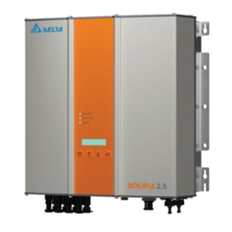
Page 7: Equipment Overview
Equipment overview (1) Connections for solar modules (2) DC disconnector (3) Grid connection (4) Interface connection RS485 (EIA485) (5) Display for status messages and keypad for operation (6) Light-emitting diodes for operational status display... -
Page 8: Installation
Installation Installation and commissioning must only be carried out by qualified electrical experts. The recommended safety regulations, the technical interface conditions (TAB 2000), as well as DIN VDE 0126-1-1, EN 50438, ENEL G.L. 12/2008 and RD 1663 specifications, should be complied with. To carry out an energy measurement, a meter must be attached between the grid feed-in point and the solar inverter (in accordance with your local utility company directive concerning „In-plant generation systems on the low-voltage grid“). By means of the integrated anti-islanding protection, the function of the recommended section switch is fulfilled in accordance with your local utility company directive. Caution: The secondary short-circuit current rating is increased at the transfer connection point to the public electricity supply system by the nominal current of the connected solar inverter. Installation of equipment Installation location • Install the device on a non-flammable support base. -
Page 9: Maintenance
Maintenance Make sure that the device remains uncovered while in operation. To avoid the casing of the solar inverter becoming soiled, it should be cleaned periodically. User-serviceable parts are not contained in the device. Under no circumstances should the solar inverter be opened! Installation You should utilize the delivered mounting plate for problem-free installation of the solar inverter. Installation to the wall should be implemented with the proper screws. Mount the wall bracket so that the solar inverter can be easily attached to the wall. After that, the device should be bolted on securely. Assembly instructions Mount the mounting plate with appropriate screws (max. Ø 6mm) into at least four of the eight holes to fix the wall bracket in place. You can employ the mounting plate as a template for marking the positions of the boreholes. As the solar inverter weighs 21.5 kg, it should be lifted out of the transport crate by at least two persons. Place the solar inverter onto the mounting plate with at least two persons. Fasten the supplied mounting nuts and washers on the threaded bolt intended for secu- ring the device. Check that the solar inverter is securely seated. Mounting plate Locking screw Locking screw 319.5 410 ± 0.5... -
Page 10: Ambient Temperature
Ambient temperature The solar inverter can be operated in an ambient temperature between -25°C to +60°C. The following diagram illustrates how the power supplied by the solar inverter is reduced automa- tically in accordance with ambient temperature. The device should be installed in a well-ventilated, cool and dry location. Grid connection The grid (AC output) is connected over a Wieland RST25i3S AC connector. You can find the cor- rect allocation on the screw-type terminal connection of the connector. The solar inverter must be connected to the grid over a three-core line (L, N, PE). The connected AC line must be switched potential-free before the disconnection or the insertion of the AC connector. The connection to the Wieland AC connector must be made with a flexible line and a conductor cross section of min. 2.5 mm² to max. 4.0 mm². An automatic circuit breaker is to be provided in the line L upstream of every device, with a nominal current of 16 A and tripping characteristic type B. In addition, attention is to be paid to the selectivity of the fuse unit attached upstream of the automatic circuit breaker. The solar inverter must be grounded via the AC connector’s PE conductor. To do this, connect the PE conductor to the designated terminal. If you wish to integrate more than one inverter into the installation, please proceed as illustrated in the drawings in the appendix. Please note the cable length and the cable cross-section, due to the risk of undesirable temperature rise and power losses. The AC connector is protected from unintentional disconnection by a clip mechanism which can be released with a screwdriver. Connection of PV modules Before the photovoltaic system is connected, the polarity of the PV voltage at the Tyco connectors must be checked to ensure that it is correct. The connection of the PV module is implemented using Tyco Solarlok connectors, where the DC negative pole is located on the connector upper row and the DC positive pole on the connector lower row. The connectors are coded to prevent you from accidentally plugging them into the wrong terminal. - Page 11 The solar inverter has an insulation and grounding monitoring on the DC side. The options can be configured in the Setup menu “6. S -> Solar ISO / GND” (see page 23, section 7.3.8). The insulation monitoring has two modes: • ISO-ON-Error (the solar inverter is disconnected from the grid in the event of an insulation fault) • ISO-ON-Warning (the solar inverter indicates the fault but is not disconnected from the grid). Deltas solar inverters are factory-set to ISO-ON-Warning mode on delivery. The grounding monitoring has two modes: • PV+ grounding (grounding monitoring of the positive pole of the PV generator) • PV- grounding (grounding monitoring of the negative pole of the PV generator). In these modes the solar inverter remains in feed-in operation and will not be disconnected from the grid in case of a fault. The error message “PV+ grounding fault” or “PV- grounding fault” will appear on the display. If you need to connect the positive or negative pole of the PV system to meet requirements set out by the module manufacturer, you can do this. Earth continuity must be implemented close to the inverter. We suggest using Deltas grounding kit “Grounding Set A Solar” (EOE 99000115). The grounding connection is monitored and should be configured in the Setup menu (see above). Alternatively, it is possible to turn off the insulation- and grounding monitoring: • ISO / GND OFF. Required cable coupler types for DC cable connection to inverter: CABLE WIRE SIZE WIRE SIZE WIRE SIZE FEMALE CA- FEMALE CABLE TYCO COUPLER 2.5 MM 4.0 MM 6.0 MM BLE COUPLER COUPLER...
-
Page 12: Output Power Over Pv Voltage
6.7.1 Output power over PV voltage 3700 W 3500 W 3300 W 3100 W 2900 W 2700 W 2500 W 350 VDC 400 VDC 450 VDC 150 VDC 200 VDC 250 VDC 300 VDC 6.7.2 Output power over AC voltage 3700 W 3500 W 3300 W... -
Page 13: Efficiency
6.7.3 Efficiency The best efficiency of the solar inverter is obtained at input voltages >250 V. 96 % 94 % 92 % 90 % 88 % 86 % 84 % 800 W 1600 W 2400 W 400 W 1200 W 2000 W 2500 W @ 450 V 2500 W @ 125 V 2500 W @ 250 V 2500 W @ 350 V Interface connection RS485 (EIA485) The interfaces not used must always be closed off. In case of utilization of an interface, only the... - Page 14 Connector pin assignment RS485 (EIA485) Not used Not used Not used GND (RS485) TERM (RS485) RX_B (RS485) TX_A (RS485) Not used Top View When several devices are connected in series and the total length of the data line measures 2 m or more, the following options are available for terminating the RS485 (EIA485) interface: Not used TX_A...
-
Page 15: Electrical Connection And Operational Start-Up
Anti- Communi- Power islanding cation controller protection Operating- and system control String A Public MPP- Isolation grid Tracker String B Booster String C Solar inverter Electrical connection and operational start-up The electrical connections are utilized on this solar inverter using the connector contacts which are attached to the casing. Under no circumstances should the device be opened! -
Page 16: Setup / Settings
1. Turn off the DC disconnector. 2. DC connection: First, connect the PV module strings to the DC Tyco Solarlok connectors (ensure correct polarity). 3. AC connection: Please install the Wieland AC mating connector to the AC output cable and then plug the AC connector to the solar inverter. Please make sure, that the sleeve nut is properly fixed and tighten. 4. Before switching on the power, check all feeders and connections one last time. 5. Turn on the DC disconnector. 6. Close the circuit breaker on the AC output side. 7. In case of sufficient PV voltage (UPV > 150 V), the device now goes into the feed-in operation. 8. In case of a new installation the time and date have to be set in sub-menu S (Setup) (see page 23, section 7.3.8). All unoccupied connectors and interfaces must be sealed using the provided sealing plugs. 6.10 Setup / settings The default display language for solar inverters leaving the Delta factory is set to English. After connecting to correct DC voltage and running through self-test, you will be asked to specify the network ID and to select the desired country (see page 23, section 7.3.8) (countries available: Germany, France, Italy, Spain, Greece, Portugal, Czech Republic and Belgium)). The selection has to be confirmed another time by the user. Once confirmed, the network ID and the country selection are stored to the controller memory – and the solar inverter is ready for operation. Please note that the enter keys on the display are locked, if there is no input entry within 5 minutes. To unlock the enter keys, you need to switch off the DC voltage and then switch it on again. Country selection Possible countries: Belgium Czech France Germany Enter network ID Greece continent Greece island... -
Page 17: Led Operation And Fault Display
Please note, that once the country has been selected and confirmed, it is only possible to change the country by following the steps as listed below: 1. Please click ESC + for few seconds to get the key information. 2. Provide the key code to the Solar Support Team at support@solar-inverter.com to get the PIN code (valid for one use only!). 3. Once you get the PIN code, you need to press ESC + . 4. Then, you will be asked to insert the PIN code and to confirm it twice. 5. After confirmation, you will then be able to select the desired country. Note: These steps must be executed without interruption. Otherwise, you will stay in the country selection mode. 6.11 LED operation and fault display Three light-emitting diodes (LEDs), which display the operational state of the solar inverter, are at- tached on the front: • LED (A), green: „Operation“ displays the operational state. Operation • LED (B), red: „Earth Fault“ displays an insula- tion resistance fault or PV grounding (GND) Earth Fault (B) fault on the DC side. Failure • LED (C), yellow: „Failure“ displays existing faults internally or externally and whether the grid feed-in operation has been interrupted. LED STATUS OPERATIONAL STATE EXPLANATION green: <off> The input voltage (UPV) is lower than 100 V. red: <off> Night disconnection. The solar inverter is not feeding power to the grid. -
Page 18: Operating Concept
Operating concept The display The display on the device indicates varied information. The enter keys are used for the adjustment of the device and for the retrieval of information. The measured data can deviate with a tolerance of up to 5%. Key (A), ESC: To switch from the menu items to the main menu and to exit each sub-menu. Key (B) and (C): For scrolling in the individual menu items and/or carrying out adjustments in the setup menu. Key (D), ENTER: ENTER key for changing into the menu levels and for input acknowledgement in the setup menu. Navigation in the display Lighting of the display After pressing the ENTER key in automatic operation, the display lighting is switched on. If no key is pressed within 30 seconds, the display lighting automatically goes out. The setup menu enables selection between continuous or automatic lighting. Through pressing the ENTER key, the display lighting is switched on again. Main menu The main menu consists of 8 menu items which are subdivided into submenus: • Menu Autotest • Menu N (Now) • Menu D (Day) • Menu W (Week) • Menu M (Month) • Menu Y (Year) • Menu T (Total) • Menu S (Setup) Handling of the menu items: You can scroll the main menu by activating the selector keys Press the ENTER key to select the submenus. In order to exit the menus again, activate the ESC... - Page 19 User menu Up to 1 Menu N - Now (act data) Submenu N - Now ENTER Down Menu D - Day statistic Submenu D - Day ENTER Down Menu W - Week statistic Submenu W - Week ENTER Down Menu M - Month statistic Submenu M - Month ENTER Down...
-
Page 20: Autotest (Only For Italy)
7.3.1 Autotest (only for Italy) This function is available only for the Italian country. The inverter is supplied with an auto-test function able to verify the correct operation of the interface protection. In the main menu, using buttons , select the auto-test menu. The display shows, for example: Autotest Passed Start Autotest? The first line shows the actual auto-test status which could be “passed” or “failed”. Pressing the auto-test routine starts. The first test performed is the OVT, over voltage test, which verify the over voltage protection. The display shows: L: 262 V < 0.1 S Start OVT test? The first line shows the actual over voltage limit and detection time settings according to the stan- dards. Pressing the test starts. Pressing “ESC” the display goes back to the main menu. If has been pressed the display shows, for example: L: 262 V A: 230 V After few seconds needed from the inverter to switch to the test mode, the limit “L:” will decrease till crossing the actual measured grid voltage “A:”. Reached this condition the inverter display shows, for example: L: 230 V 0.044 S A: 230 V OV pass... - Page 21 The limit “L:” will increase till crossing the actual measured grid voltage “A:”. Reached this condition the inverter display shows, for example: L: 230 V 0.164 S A: 230 V UV pass The first line shows the limits according the standard. The second line shows the actual measured grid voltage and the test status, positive (pass) or negative (fail). Pressing the test is confirmed and the auto-test routine continue. If no is pressed, the result is shown for 1minute. After this time, the result is confirmed automatically. If the test is confirmed, the inverter performs the HFT test, high frequency test, which verify the high frequency protection. The display shows: L: 50.30 Hz < 0.06 S Start HFT test? The first line shows the actual high frequency limit and detection time settings according to the standards. Since the protection is not sensitive to the frequency variations less than 40 ms (two line cycles of the grid voltage at nominal frequency of 50 Hz), the detection time has been set to 60 ms. Pressing the test starts. Test starts also automatically after 1 minute if no is pressed. If has been pressed the display shows, for example: L: 50.30 Hz A: 49.99 Hz The limit “L:” will decrease till crossing the actual measured grid frequency “A:”. Reached this con- dition the inverter display shows, for example: L: 49.99 Hz 0.044 S A: 49.99 Hz HF pass The first line shows the limits according the standard. The second line shows the actual measured...
- Page 22 If has been pressed the display shows, for example: L: 49.70 Hz A: 49.99 Hz The limit “L:” will increase till crossing the actual measured grid frequency “A:”. Reached this condi- tion the inverter disconnects from grid and the display shows, for example: L: 49.99 Hz 0.044 S A: 49.99 Hz LF pass The first line shows the limits according the standard. The second line shows the actual measured grid frequency and the test status, positive (pass) or negative (fail). Pressing the test is confirmed and the auto-test routine continue. If no is pressed, the result is shown for 1minute. After this time, the result is confirmed automatically. If the test is confirmed, the auto-test routine is finished. The display shows, for example: Autotest Passed Esc to continue First line shows the actual auto-test status. If all the single test are passed and confirmed, the actual auto-test status will be passed. Pressing “ESC” the display goes back to the main menu. If the actual auto-test status is failed, pressing “ESC” the display goes back to the main menu and the inverter is in error condition. The display shows “ AUTOTEST FAILED”. If the actual status is failed it’s possible to restart the auto-test routine. If the auto-test permanently fails please contact the customer service. If during the auto-test is performed any grid or inverter errors occurs, the auto-test routine is aborted and the display shows the actual failed auto-test status. The inverter reset and perform a restart if the previous status was passed. The auto-test can be started only if the inverter is in normal operating conditions. It is not possible to entry the auto-test routine if the grid is not in the defined tolerances, if any internal inverter error occurs or the solar plan do not respect the specifications.
-
Page 23: Submenu N (Now)
7.3.2 Submenu N (Now) This menu item displays the active values. Main menu N - Now ENTER Submenu N - Now actual data Up to 1 Display of the N -> AC-Power Value (W) active output power Down Display of the active N -> AC-Voltage Value (V) output voltage Down Display of the active... -
Page 24: Submenu W (Week)
7.3.4 Submenu W (Week) This menu item displays the average values of the current week. ENTER Main menu W - Week statistic Submenu W - Week Up to 1 Display of the weekly W -> Energy Value (kWh) energy gain Down W -> AC-Revenue Display of the weekly revenue Value (Euro) Down Display of the weekly operating W ->... -
Page 25: Submenu T (Total)
7.3.7 Submenu T (Total) This menu item shows cumulated and maximum/minimum values since first use. ENTER Main menu T - Total statistic Submenu T - Total Up to 1 Display of the total T -> Energy Value (kWh) energy gain Down T -> Revenue Value Display of the total (Euro) revenue Down T ->... -
Page 26: Submenu S: Solar Iso / Gnd
7.3.8.1 Submenu S: Solar ISO / GND More detailed information on the Solar ISO / GND menu within the submenu S (Setup). Submenu Setup ENTER Solar ISO / GND Up to 6 Use old setting S -> Solar ISO / GND ENTER ISO ON-Warning Down S -> Solar ISO / GND ENTER ISO ON-Failure Down S ->... -
Page 27: Submenu S: Firmware
7.3.8.3 Submenu S: Firmware More detailed information on the firmware menu within the submenu S (Setup). Submenu Setup ENTER Firmware Up to 3 S -> Firmware AC-Ctrl maj.min.bug Down S -> Firmware DC-Ctrl maj.min.bug Down S -> Firmware SC-Ctrl maj.min.bug Down S -> Firmware Display-Ctrl maj.min.bug Down to 4 Diagnostics and data evaluation Malfunction rectification The solar inverter is provided with an automatic diagnostics system which independently identifies certain faults and which can make them visible on the display. -
Page 28: Display Messages
Display messages DISPLAY LED STATUS CAUSE ELIMINATION MESSAGE green: <on> - If the fault persists after the device has Display communication red: <on> - been reset, please inform your service faulty. yellow: <on> technician. green: <off> Grid frequency overshoo- AC frequency - Check the grid frequency via the display red: <off> ting or undershooting failure in the N menu. yellow: <on> specified limit range. - Check the grid voltage via the display in green: <off> Grid voltage overshooting AC voltage the N menu. red: <off> or undershooting specified failure - If no voltage present, check grid auto- yellow: <on> limit range. matic circuit breaker. green: <off> Autotest failed The autotest status is in red: <off>... - Page 29 DISPLAY LED STATUS CAUSE ELIMINATION MESSAGE The first time the solar inverter is started green: <on> Self test Initialization of solar inver- red: <on> ongoing ter on start-up. - Normal function with a PV cell voltage yellow: <on> of between 100 V and 150 V. green: <flashes> - Insufficient insolation (dawn/twilight). PV power too red: <off> Insufficient input power. - Check the PV cell voltage via the yellow: <off> display in the N menu. green: <flashes> - Insufficient insolation. PV voltage too PV generator voltage bet- red: <off> - Check the PV cell voltage via the ween 100 V and 150 V. yellow: <off> display in the N menu. green: <flashes> Check grid voltage and Synchronize red: <off> grid frequency for grid - Normal function before input mode. to AC yellow: <off>...
-
Page 30: Technical Data
Technical data INPUT (DC) OUTPUT (AC) Max. recommended PV 3100 W Max. power 2600 W power Nominal power 2750 W Nominal power 2500 W Voltage range 125 ... 540 V Voltage range 184 ... 264 V * MPP range 150 ... 450 V Nominal current 11.0 A Full power MPP range 150 ... 450 V Max. current 13.0 A Nominal current 10.0 A Nominal frequency 50 Hz Max. current 18.0 A Frequency range 47.0 ... 52.0 Hz * Stand-by power < 0.2 W Power factor > 0.99 @ nominal power Total harmonic < 3 % @ nominal power distortion (THD) MECHANICAL DESIGN... -
Page 31: Appendix
Appendix 10.1 Connection examples Individual in-plant generation system in parallel operation without isolated operation possibility, single-phase feed with anti-islanding protection. Low-voltage network ~ 400 / 230 V House connection line House connection box Owner boundary Customer Measurement unit (1) Meter for power consumption (2) Meter for power feed-in with back stop in each case Remark: A meter can also be employed... -
Page 32: Overview Of Connection Diagrams
10.2 Overview of connection diagrams PV generator PV generator DC terminal strip DC disconnector Meter for power consumption Consumer equipment Solivia 2.5 Automatic Selective House circuit breaker Meter for main line connection type B 16 A power feed-in circuit breaker... - Page 33 PV generator DC disconnector Solivia 2.5 Fuse...
-
Page 34: Glossary
Glossary Abbreviation for „Alternating Current“. Anti-islanding protection This is a unit for grid monitoring with assigned switching elements (anti-islanding protection) and is an automatic isolation point for small power generation systems (to 30 kWp). BDEW Union of German Electrical Power Stations. With the CE identification code, the manufacturer confirms the conformity of the product with the valid EC Guideline and compliance with the significant requirements stipulated therein. Abbreviation for „Direct Current“. The Electro-Magnetic Compatibility (EMC) concerns the technical and legal basics of the mutual influencing of electrical devices through electromagnetic fields caused by them in electrical engi- neering. Galvanical isolation No conductive connection between two component parts. Initialization Under initialization (cf. English to initialize) is understood the part of the loading process of a pro- gram, in which the storage space required for the execution (e.g. variable, code, buffers ...) for the program is reserved and is filled with initial values. Local utility company By local utility company is meant a company which generates electrical energy and distributes it over the public grid. The Maximum Power Point is the point of the current-voltage diagram of a PV cell at which the largest power can be tapped off, i.e. the point at which the product of current and voltage has its maximum value. - Page 35 Photovoltaics (abbr.: PV) The conversion of PV energy into electrical energy. The name is composed of the component parts: Photos - the Greek word for light - and Volta - after Alessandro Volta, a pioneer in electrical research. Power dissipation Power dissipation is designated as the difference between absorbed power and power of a device or process yielded. Power dissipation is released mainly as heat. PV cell PV cells are large-surface photodiodes which convert light energy (generally sunlight) into electrical energy. This comes about by utilization of the photoelectric effect (photovoltaics). PV generator System comprising a number of PV modules. PV module Part of a PV generator; converts PV energy into electrical energy. RJ45 Abbreviation for standardized eight-pole electrical connector connection. RJ stands for Registered Jack (standardized socket). RS485 (EIA485) Differential voltage interface on which the genuine signal is transmitted on one core and the ne- gated (or negative) signal on the other core. Separate grid system Energy supply equipment which is completely independent of an interconnected grid. Solar inverter is an electrical device which converts DC direct voltage into AC voltage and/or direct current into alternating current. String Designates a group of electrical PV modules switched in series. String solar inverter (solar inverter concept) The PV generator is divided up into individual strings which feed into the grid over their own string solar inverters in each case. In this way, the installation is considerably facilitated and the gain de- crease, which can arise from the installation or from different shading conditions of the PV modules,...
-
Page 36: Certificates
Certificates... - Page 43 Notes...
- Page 44 Delta Energy Systems (Germany) GmbH Tscheulinstrasse 21 79331 Teningen Germany Sales Email: sales@solar-inverter.com Support Email: support@solar-inverter.com Sales Hotline: 0180 10 SOLAR (76527) Support Hotline: 0180 16 SOLAR (76527) Mondays to Fridays from 8 am to 5 pm (apart from official Bank Holidays) (3.9 ct/min.)