
Related Manuals for IVT GreenlineC


Summary of Contents for IVT GreenlineC
- Page 1 Greenline C, D and E Guide to installation, commissioning and maintenance Article nr: 290407-9 Version: 5.1...
-
Page 2: Important Information
• The heat transfer fluid system must be in operation when venting the system. See chapter on refilling the heat transfer circuit. • The control unit measures the phase sequence and alarms if the power is connected wrongly (only 3-phase units). IVT Industrier AB June 2003... -
Page 3: Table Of Contents
Table of Contents PAGES FOR THE HOUSE OWNER This is how your heat pump works:_____________________________________________ 7 Heat pump technology _______________________________________________________________________ 7 Heat pump components ______________________________________________________ 8 C series components ________________________________________________________________________ 8 D and E series components ___________________________________________________________________ 9 Principle _________________________________________________________________ 10 Principle of heating and hot water control ______________________________________________________ 10 Power failures ____________________________________________________________________________ 10 Three different operating modes ______________________________________________ 10... - Page 4 Setting the heating _________________________________________________________ 18 How to increase or reduce the heating in your house ______________________________________________ 18 Fixed temperature (D series only) _____________________________________________ 20 Setting the heating at fixed temperature ________________________________________________________ 20 Simple tips for saving _______________________________________________________ 20 Utilising the heat pump in the right way ________________________________________________________ 20 All sensor temperatures _____________________________________________________ 21 Description of all temperatures _______________________________________________________________ 21 If something is wrong ______________________________________________________ 22...
- Page 5 Filling ___________________________________________________________________ 43 Filling the radiator system ___________________________________________________________________ 43 Filling of heat transfer fluid __________________________________________________________________ 43 Electrical connections ______________________________________________________ 45 Circuit diagram Greenline C series. Factory connections ___________________________________________ 45 Circuit diagram Greenline D series. Factory connections ___________________________________________ 46 Circuit diagram Greenline E series. Factory connections ___________________________________________ 47 Working switch ___________________________________________________________________________ 48 Earth fault breaker _________________________________________________________________________ 48 External connections in the C and E series.
-
Page 6: This Is How Your Heat Pump Works
This is how your heat pump works: Heat pump technology The compressor, which is driven by an electric motor, forces the refrigerant into the heat pump condenser as a gas at about 100°C. The gas and the water from the radiator system pass through the condenser, which is a fully-welded stainless steel heat exchanger. -
Page 7: C Series Components
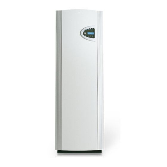
C series components Please note: The picture shows a 1-phase unit. Electrical connection. 3-way valve that switches between heating and Control panel with large domestic hot water. display. Double-shelled hot water heater. Enclosed electrical box with motor protection reset and circuit breaker for heat pump and immer- sion heater. -
Page 8: D And E Series Components
D and E series components Please note: The picture is of the E series, 1-phase. The D series has two connections on the hot side and does not include a 3-way valve and immersion heater. The particle filter is supplied separately and is mounted outside the heat pump. Electrical connection. -
Page 9: Principle
Principle Principle of heating and hot water control Your heat pump is fitted with a Rego600 control unit to guarantee you maximum savings and many years of service. The unit, which has advanced monitoring functions, controls the heating and hot water in your home. -
Page 10: Controls
Controls The control unit operates the heat pump in three ways. We call them Curve Control, Room Sensor and Fixed Temperature. Below follows a brief description. Curve control (operating modes A and B) This is the most common mode and is also the factory setting. This means that the heat pump adjusts the heat in the house based on the outdoor temperature so that the radiator temperature increases as the outdoor temperature reduces. -
Page 11: Control Panel
Control panel Control panel buttons and displays The control panel is the heart of your heat pump installation. From the control panel, instructions are sent to the Rego600 control unit, which ensures that the house is uniformly heated. All settings are carried out here and the display shows the settings that have been set. -
Page 12: How To Use The Control Panel
How to use the control panel With three buttons and a knob you can navigate to the various displays for settings and readings. The last line at the bottom of the display contains information about the functions of the buttons in the current display. -
Page 13: Heating And Extra Hot Water
Basic functions (at customer level 1) Rego600 020312 12.00.00 Heating and extra hot water Heat Info Menu Press Heat to come to the short cut to the heat settings. These displays are then available. Temp. incr. / decr. House heating settings in areas 0 to 10. See more detailed description in Heat Settings chapter. -
Page 14: Line 1
Enhanced functions Rego600 020312 12.00.00 As user you have access to extra functions. Keep the Heat button Heat Info Menu pressed down for five seconds and go into Menu to gain access to these displays. You will automatically return to level 1 again after 30 seconds. -
Page 15: Clock Settings
Line 4 Main menu You have now moved to timer control settings line 4. Timer control settings Return Select Here you can set the times day for day that you want to Clock setting utilise the clock settings. You can set all the weekdays Clock setting HP accord. -
Page 16: Line 7
Line 7 Main menu In line 7 you can read the running times for the heat pump Op. time readings on and additional heat. Press “Select” to enter these menus. HP and add. heat Return Select Op. time readings Here you can see how many hours the heat pump has been in Heat pump in operat. -
Page 17: Setting The Heating
Setting the heating Rego600 In the Temperature increase/decrease display 020312 12.00.00 Heat Info Menu you use the knob to change the heat curve. The lines show how the return temperature varies with the outdoor temperature for different settings. The colder the weather the warmer the heating system. - Page 18 The heat curve can also be fine tuned. You do this in the Temp. fine tune display. The dotted line illus- trates how the parallel offset has been turned towards plus. The entire curve moves upwards, in contrast to increasing the slope, when only the slope changes. Radiator return Fine tuning adjustment temperature...
-
Page 19: Fixed Temperature (D Series Only)
Fixed temperature (D series only) If the heat pump is set at operating mode C with a fixed temperature, then it can only be engaged and disengaged by the built-in return sensor. There are two displays available for this mode. Please note that if a mixing valve is connected to the heat pump, the Temp. -
Page 20: All Sensor Temperatures
All sensor temperatures Below are the various sensor temperatures that are visible under line 3 in the control panel. Note that not all the sensors are standard but are available as accessories for different areas of use. To get there press ”Menu”... -
Page 21: If Something Is Wrong
If something is wrong The control unit provides a lot of information about faults and how to remedy them. The control unit incorporates advanced functions to monitor and protect your heat pump. This means there is no risk involved in resetting an alarm. If a fault persists, you should contact the installer. Alarm examples and what to do ALARM Cause... -
Page 22: All Alarms
All alarms Below is a description of the alarms that can appear in the menu display. The description gives an idea of what the fault is and what you yourself can check and remedy. An alarm can sometimes occur temporarily so there is never any risk with resetting it. If a fault persists, you should contact the installer. - Page 23 ALARM ON PRESSURE SWITCH LOW ALARM (LP) To reset the alarm: Press ”Ackn”. Low pressure switch 020312 16.08.15 Info Ackn. Probable causes and actions: • Air in the heating system. Action:Check the expansion vessel and fill if required. If air is heard continuously in the system, contact the installer.
- Page 24 ALARM ON COMPRESSOR SUPERHEAT ALARM (GT6) To reset the alarm: Press “Ackn”. Compressor superheat 020312 16.08.15 Info Ackn. Probable causes and actions: • The working temperature of the compressor is too high. Action: If the fault persists, contact the installer. •...
- Page 25 ALARM, HIGH RETURN TO THE HEAT PUMP ALARM (GT9) To reset the alarm: The alarm resets itself and the heat pump High return HP starts automatically when the temperature has dropped. 020312 16.08.15 Info Ackn. Probable causes and actions: The heat pump has a sensor that stops the heat pump for safety reasons when the return temperature is too high, about 48°C.
-
Page 26: Maintaining Your Heat Pump
Maintaining your heat pump Your heat pump normally requires little maintenance, but we recommend occasional checking to ensure that your heating installation give the best possible performance. The description sometimes refers to a heat pump component. You find these on the following pages. Working on the heat pump •... -
Page 27: Control Safety Anode
Control safety anode (Only for models with stainless hot water cylinder) At the top of the hot water cylinder, under the insulation, there is an electronic protection anod (standard feature) Its purpose is to prevent corrosion. The cylinder must be full of water for the anode to work. If the heat pump is equipped with a magnesium anode, the anode can corrode depending on the water quality. -
Page 28: The Various Parts In The D And E Series
The various parts in the D and E series Please note: The picture is of the E series, 1-phase. Pos 2 Reset, motor cutout compressor. Pos 1 Cleanable particle filter Pos 3 with cut-off Reset circuit breaker heat pump. Pos 4 Reset circuit breaker immersion heater. -
Page 29: What The Shipment Includes
What the shipment includes Standard components • heat pump unit with the necessary safety functions and electrical components • factory mounted control unit Rego600. Rego600 can be used for simultaneous operation together with an immersion heater or oil-fired or electric boiler with mixing valve. •... -
Page 30: Dimensions And Connections, C Series
Dimensions and connections, C series Dimensions are given in mm 1770 ® 460 525 ® ® ® ® ® (1) Return radiator (2) Riser radiator (3) Cold water in (4) Hot water out (5) Heat transfer fluid in (6) Heat transfer fluid out Electrical connections Front... -
Page 31: Dimensions And Connections, D And E Series
Dimensions and connections, D and E series Dimensions are given in mm 1500 ® ® ® ® (1) Return radiator Electrical (2) Riser radiator connections (3) Return DHWC (4) Riser DHWC (5) Heat transfer fluid out (6) Heat transfer fluid in The D series does not have Pos. -
Page 32: Collector Hose
Collector hose The collector hose consists of a thin-walled plastic hose of make Pem 40 x 2.4 DN 6.3. Length and depth as in IVT:s dimensioning program. Install the hose rising towards the heat pump to avoid air pockets. It is vitally important that the filling around the ground coil does not contain stones or other objects that could damage the coil. -
Page 33: Connecting The Collector To The Heat Pump
Connecting the collector to the heat pump The sketch shows the connection of a collector with two parallel coils. Both coils are connected to two distributors. Each coil should have a gate valve and a control valve. The control valve is adjusted so that the flow is the same in both coils. -
Page 34: Switching To Side Mounting Of The Fluid Transfer System
Switching to side mounting of the heat transfer fluid system When delivered Greenline Compact is designed for top mounting on the heat transfer fluid (collector) side. This can be changed to side mounting on the right or left side. The following instructions de- scribe the process step by step. - Page 35 RIGHT MOUNTING Heat transfer fluid in is cut as shown in figure A. Heat transfer fluid out can be cut as shown in figure B then a bend and a straight piece of copper pipe can be soldered in. The piece of pipe can be taken from the piece that was over when the pipe was cut.
-
Page 36: Ground Water System
Connecting to the heating system General Installation must be carried out by an authorised installer and must follow the current rules and recom- mendations of IVT. The pipework must be flushed before the heat pump is connected to protect the heat pump from contaminants. -
Page 37: Connecting The C Series To The Heating System And Operating Mode A
Connecting the C series to the heating system and operating mode A Application: The principle for operating mode A is based on liquid condensation and additional heat from an electric water heater. The built-in control unit Rego600 controls the heat pump with an outdoor sensor GT2 and return sensor GT1 according to outdoor compensated control curve. -
Page 38: Connecting The D Series To The Heating System And Operating Mode A
Connecting the D series to the heating system and operating mode A Application: The principle for operating mode A is based on liquid condensation and additional heat from an immersion heater. The built-in control unit Rego600 controls the heat pump with an outdoor sensor GT2 and return sensor GT1 according to outdoor compensated control curve. -
Page 39: Connecting The E Series To The Heating System And Operating Mode A
Connecting the E series to the heating system and operating mode A Application: The principle for operating mode A is based on liquid condensation and additional heat from an immersion heater. The built-in control unit Rego600 controls the heat pump with an outdoor sensor GT2 and return sensor GT1 according to outdoor compensated control curve. -
Page 40: Connecting The D Series To The Heating System And Operating Mode B
Connecting the D series to the heating system and operating mode B Application: The principle for operating mode B is based on liquid condensation and additional heat from an oil-fired boiler using a mixing valve. The built-in control unit Rego600 controls the heat pump with an outdoor sensor GT2 and return sensor GT1 according to outdoor compensated control curve. -
Page 41: Connecting The D Series To The Heating System And Operating Mode C
Connecting the D series to the heating system and operating mode C Application: The principle for operating mode C is based on a fixed temperature and additional heat from an immersion heater. Rego600 controls the heat pump with a built-in return sensor, GT9. When the heat pump is not able to meet the heating requirements, the water heater starts automatically and together with the heat pump provides the required temperature. -
Page 42: Connecting The 3-Way Valve
Connecting the 3-way valve Connecting a Honeywell 3-way valve to hot water cylinder. Port B / to radiators. Port A / to DHW cylinder Port AB / from heat pump Filling the radiator system Note that the radiator system must have its own expansion vessel. Open the valve between the cold water system and the heating system in short bursts and then close it and note the pressure gauge reading. - Page 43 Brinol and 200 x 0.71 litres water/ metres = 142 litres water. Filling and venting valve Expansion vessel Safety valve *Manual venting valve *If the expansion vessel cannot be placed in the highest position then manual venting is recommended. Particle filter IVT Greenline...
- Page 44 Circuit diagram Greenline C4 3x400V Givarkort interna kopplingar Sensor Board internal couplings SERVICE GT9 GT10 GT11 L2 L3 Varmvatten/ Hot water T6: Kompressor/ Compressor ÖH Värmebärare ut/ Heat transfer fluid out Värmebärare in/ Heat transfer fluid in T10: Köldbärare in/ Heat transfer fluid (coll) in T11: Köldbärare ut/ Heat transfer fluid (coll) out Pressostat hög/ High pressure switch...
- Page 45 Circuit diagram Greenline C5-C9 3x400V Givarkort interna kopplingar Sensor Board internal couplings SERVICE GT9 GT10 GT11 L2 L3 Varmvatten/ Hot water T6: Kompressor/ Compressor Värmebärare ut/ Heat transfer fluid out ÖH Värmebärare in/ Heat transfer fluid in T10: Köldbärare in/ Heat transfer fluid (coll) in T11: Köldbärare ut/ Heat transfer fluid (coll) out Pressostat hög/ High pressure switch...
- Page 46 Circuit diagram Greenline D5-D11 3x400V Givarkort interna kopplingar Sensor Board internal couplings SERVICE GT9 GT10 GT11 L2 L3 Kompressor/ Compressor Värmebärare ut/ Heat transfer fluid out Värmebärare in/ Heat transfer fluid in T10: Köldbärare in/ Heat transfer fluid (coll) in T11: Köldbärare ut/ Heat transfer fluid (coll) out Pressostat hög/ High pressure switch...
- Page 47 Circuit diagram Greenline E5-E11 3x400V Givarkort interna kopplingar Sensor Board internal couplings SERVICE GT9 GT10 GT11 L2 L3 Kompressor/ Compressor Värmebärare ut/ Heat transfer fluid out ÖH Värmebärare in/ Heat transfer fluid in T10: Köldbärare in/ Heat transfer fluid (coll) in T11: Köldbärare ut/ Heat transfer fluid (coll) out Pressostat hög/ High pressure switch...
- Page 48 Circuit diagram Greenline D5-D11 3x400V Givarkort interna kopplingar Sensor Board internal couplings SERVICE GT9 GT10 GT11 L2 L3 Kompressor/ Compressor Värmebärare ut/ Heat transfer fluid out Värmebärare in/ Heat transfer fluid in T10: Köldbärare in/ Heat transfer fluid (coll) in T11: Köldbärare ut/ Heat transfer fluid (coll) out Pressostat hög/ High pressure switch...
-
Page 49: External Connections In The C And E Series
Disconnection switch • The heat pump must always have a main switch connected. Earth leakage circuit breaker • If the heat pump is connected over a leakage circuit breaker then a separate leakage circuit breaker is recommended for the heat pump. External connections in the C and E series. -
Page 50: External Connections In The D Series
External connections in the D series • Power supply: Connect to terminals L1, L2, L3, N and PE. Alarm triggers if phases connected wrongly. • 3-way valve: Connected if the heat pump is to produce hot water. Connected to terminals VXV. •... -
Page 51: Connecting The General Alarm
Connecting the general alarm A general alarm is connected according to the sketch. The contact for the general alarm outlet is floating. Max 24 volt, 100mA. The contact shuts at joint alarm. Terminal card internal couplings ALARM GENERAL ALARM Floating general alarm outlet. Max 24 volt, 100mA. -
Page 52: Control Unit Rego600
Control unit Rego600 If you are an installer, note that you can find certain information about the operation of the control unit in the sections that are intended for the end user. It is therefore important for installers to read the guide before putting the heat pump into service. -
Page 53: Selecting External Controls
You can shorten the time for restarting the heatpump here. If Commiss./Service there is a need for heating or hot water the heat pump starts Fast restart within 20 seconds. The settings must be repeated each time of heat pump you require quick restart. -
Page 54: Timer Reading
Line 6 To help you when checking the installation, line 6 allows you to read the timer status. Timer readings If hot water peak is selected you can see that in status. If it is Read Only in down at nought the peak is activated at the next need for operating DHW peak timer hotwater. -
Page 55: Commissioning The Heat Pump
Commissioning the heat pump Navigating the menu list • The example shows you how to navigate menu display 5.13. Main menu Rego600 Indoor temperature settings 020312 12.00.00 Return Select Heat Info Menu Keep the “Menu” button pressed ... to arrive at line 1, which is ... -
Page 56: General
General The heating and heat transfer fluid collector systems must be filled and vented before commissioning the heat pump. Check also that there are no leaks in the systems. When connecting to an existing water system, check that at least two of the radiators are always open. With underfloor heating, at least two of the circuits must be open. - Page 57 Displays you must always check Commiss./Service Select operation Always check that operating mode A is set. mode A B C Return Select Commiss./Service If you have connected any of the external sensors GT3, GT4 Connected extra or GT5 you must Ackn then so that Rego600 memorises sensor in op.
- Page 58 Commissioning operating mode B (D series only) Connect the mains voltage to the heat pump and press the ON/OFF button on the control panel. Rego600 measures the phase sequence so that the compressor does not go the wrong way, so if you receive a phase sequence alarm the main supply is cut to the heat pump and two of the phases are shifted.
- Page 59 Displays you might need to adjust or check settings Temperature settings Setting of hysteresis on the heat pump’s on and off for the Heat curve return sensor radiator GT1. A low value gives closer inter- hysteresis vals between start and stop. Return Select Setting the temperaturer in the hot water cylinder’s outer...
- Page 60 Commissioning operating mode C (D series only) Connect the mains voltage to the heat pump and press the ON/OFF button on the control panel. Rego600 measures the phase sequence so that the compressor does not go the wrong way, so if you receive an phase sequence alarm the main supply is cut to the heat pump and two of the phases are shifted.
-
Page 61: Important Points To Check
Important points to check During the first period after commissioning you should pay special attention to the pressure levels in the heating system and heat transfer circuit. It might need filling up. The factory setting of the motor cutout is based on a value under the hot water pressure and stable voltage. -
Page 62: Sensor Table
Technical spec. C5/D5/E5 C7/D7/E7 C9/D9/E9 D11/E11 Model 4.0/1.0 5.6/1.3 7.7/1.7 8.6/1.9 11.2/2.6 Emitted /Supplied output at 0/35°C 3.3/1.1 4.8/1.5 6.6/2.0 8.2/2.8 10.9/3.8 Emitted /Supplied output at 0/50°C 0.13 0.18 0.26 0.29 0.38 Nominal flow heating medium 0.22 0.31 0.46 0.50 0.64 Nominal flow cooling medium Permitted ext. - Page 63 Service log Only to be filled in by an authorised person Date Work done Company Initials .....................................................................................................................................................................................................................................................................................................................................................................................................................................................................................................................................................................................................................................................................................................................................................................................................................................................................................................................................................................................................................................................................................
- Page 64 Service log Only to be filled in by an authorised person Date Work done Company Initials .....................................................................................................................................................................................................................................................................................................................................................................................................................................................................................................................................................................................................................................................................................................................................................................................................................................................................................................................................................................................................................................................................................
- Page 65 Notes .....................................................................................................................................................................................................................................................................................................................................................................................................................................................................................................................................................................................................................................................................................................................................................................................................................................................................................................................................................................................................................................................................................
- Page 66 Notes .....................................................................................................................................................................................................................................................................................................................................................................................................................................................................................................................................................................................................................................................................................................................................................................................................................................................................................................................................................................................................................................................................................
- Page 67 Notes .....................................................................................................................................................................................................................................................................................................................................................................................................................................................................................................................................................................................................................................................................................................................................................................................................................................................................................................................................................................................................................................................................................