Table of Contents
Advertisement
INSTRUCTIONS
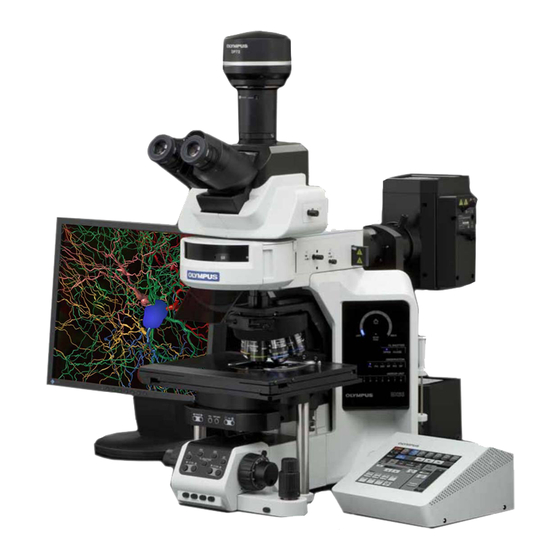
BX63
INTELLIGENT MICROSCOPE
This instruction manual is for the Olympus Intelligent Microscope Model BX63.
To ensure the safety, obtain optimum performance and to familiarize yourself fully with the use
of this microscope, we recommend that you study this manual thoroughly before operating the
microscope.
Retain this instruction manual in an easily accessible place near the work desk for future reference.
A X 7 9 3 3
Advertisement
Table of Contents

Related Manuals for Olympus BX63


Summary of Contents for Olympus BX63
- Page 1 BX63 INTELLIGENT MICROSCOPE This instruction manual is for the Olympus Intelligent Microscope Model BX63. To ensure the safety, obtain optimum performance and to familiarize yourself fully with the use of this microscope, we recommend that you study this manual thoroughly before operating the microscope.
- Page 2 Refer to your local Olympus distributor in EU for return and/or collection systems available in your country. NOTE: This equipment has been tested and found to comply with the limits for a Class A digital device, pursuant to Part 15 of the FCC Rules.
-
Page 3: Table Of Contents
BX63 CONTENTS Correct assembly and adjustments are critical for the microscope to exhibit its full performance. If you are going to assemble the microscope yourself, please read section 9, “ASSEMBLY” (pages 39 to 44) carefully. IMPORTANT -- Be sure to read this section for safe use of the equipment. --... - Page 4 CAMERA RECORDING System Chart Selecting the Camera Adapter Magnification TROUBLESHOOTING GUIDE 34,35 SPECIFICATIONS 36,37 OPTICAL CHARACTERISTICS (UIS2 Series) ASSEMBLY 39-44 -- See this section for the replacement of the halogen light bulb. -- 9-1 Assembly Diagram ................................39-42 9-2 Detailed Assembly Procedures ..........................43,44 HALOGEN LAMP HOUSING INSPECTION SHEET SET TYPE LIST 46-48...
-
Page 5: Important
This microscope employs a UIS2 (Universal Infinity System) optical design, and should be used only with modules designed for the BX3-series and with UIS2 objectives/eyepieces. For the applicable modules, please consult Olympus or the catalogues.) Less than optimum performance may result if inappropriate accessories are used. - Page 6 Operation Using the LED Lamp Safety note on LED (Light Emitting Diode) The LED incorporated in the LED lamp housing is a class 1 LED product. The light emitted by LED is basically safe, but do not look at the illumination light directly for an extended period to prevent your eye from being injured CLASS 1 LED PRODUCT Operation Using the Halogen Bulb...
- Page 7 Caution labels are placed at parts where special precaution is required when handling and using the microscope. Always heed the cautions. Lamp housing [Caution against high temperature] Caution label positions Revolving nosepiece arm [Caution against finger or hand being caught] If a caution label is dirty or peeled off, contact Olympus for the replacement or other inquiry.
-
Page 8: Maintenance And Storage
1 meter (to prevent the system from tipping over). 5. When the microscope needs to be packaged for forwarding to a remote location, contact Olympus (to obtain advice for guaranteeing the performance). Maintenance and Storage 1. -
Page 9: Intended Use
· The electromagnetic environment should be evaluated prior to operation of this product. Do not use this product in close proximity to the sources of strong electromagnetic radiation to prevent interference with the proper operation. · Use only power cord which OLYMPUS specifies. Otherwise the safety and EMC perfomance of the product can not be assured. -
Page 10: Module Nomenclature
} The modules mentioned below show only the typical product names. As there are some products that are not mentioned but also applicable to this microscope, check the latest catalogues or consult Olympus. The control of motorized modules is possible from the touch panel controller, the U-MCZ controller or a PC (commercially available). -
Page 11: Controls
BX63 CONTROLS } If you have not yet assembled the microscope, read chapter 9, “ASSEMBLY” (pages 39 to 44). Transmitted light observation combination Interpupillary distance Light path selector knob (Page 28) adjustment scale (Page 27) Display panel (See next page for details.) - Page 12 Display panel ECO mode indicator Brightness meter Shutter indicators OPEN/CLOSE Observation mode indicators FL/PH/DIC/BF/PO/DF Mirror unit indicators 1 to 8 * For details, read the separate instruction manual for “BX3-CBH/U-MCZ”. Control Box BX3-CBH The manual shows the wiring diagrams for the connection cables. Indicator LEDs POWER: Power status indicator.
- Page 13 BX63 * For details, read the separate instruction manuals for the Reflected light observation combination BX3-RFAA and U-AW. Lamp Housing for 100W Mercury Burner U-LH100HG Motorized Fluorescence Illuminator* U-LH100HGAPO BX3-RFAA Lamp Housing for 75W Xenon Burner U-LH75XEAPO Motorized Attenuator Wheel*...
- Page 14 Touch panel controller (provided with the BX63F) DC input connector Main switch 24 V, 2.8 A ON: Short push OFF: Continuous push Touch panel Signal cable Example of touch panel guidance screen OFF button Setting button Objective buttons Help button Observation mode buttons MENU button Control panel...
- Page 15 } This adapter is required when using the U-SVLB-4, U-SVRB-4, U-SVLO or U-SVRO stage for the BX series. Mounting dovetail 35 mm dish holder Cross Stage When installing this stage on the BX63, position it so that the stage knobs are on CAUTION IX-SVL2 the right.
-
Page 16: Flow Of Brightfield Observation
} This chapter describes the BF (brightfield observation) procedure of the Guidance mode. (Individual operations are explained assuming the use of the touch panel controller provided with the BX63.) } The Guidance mode button is defeated unless System Setting has been completed in the [MENU display] at the system startup. - Page 17 BX63 Motorized fluorescence illuminator BX3-RFAA Motorized attenuator wheel U-AW Motorized 7 position nosepiece U-D7REA Control box BX3-CBH Control box (for BX3-SSU) Motorized universal condenser BX3-UCD8A Controller U-MCZ XY controller Touch panel controller {MENU display {Preparations for observation {Guidance mode display...
-
Page 18: Using The Controls
USING THE CONTROLS 4-1 Touch Panel Controller · When activating the touch panel controller, first turn the BX3-CBH control box ON and then turn the touch CAUTION panel controller ON. · The touch panel controller controls the camera recording but cannot view or save the recorded images. Basic Operations of Touch Panel Controller (Fig. -
Page 19: Starting The System
BX63 Starting the System (Fig. 5) 1. Set the main switch of the BX3-CBH control box to “ I ” (ON). 2. Set the main switch on the rear panel of the touch panel controller to 3. If you are using the supersonic stage, set the main switch of its control box to “... -
Page 20: System Setting
(Fig. 7). Fig. 7 Unit Setting This tab is used to set the units connected to the BX63. 1. Tap the [Unit] tab 1 in the [System Setting] display to open the [Unit] display (Fig. 8). - Page 21 2. Tap the [Mirror Unit] tab ² in the [Optical] display (Fig. 11). 3. Register the mirror unit actually mounted on the BX63 for each mirror unit number. Tap one of the mirror unit numbers in use 3 to open the [Mirror Unit] screen for the number (Fig.
- Page 22 Condenser setting 1. Tap the [Optical] tab 1 in the [System Setting] display to open the [Optical] display. 2. Tap the [Condenser] tab ² in the [Optical] display (Fig. 13). 3. Register the optical element actually mounted on the condenser for each condenser turret position number.
-
Page 23: Selecting The Mode
BX63 Selecting the Mode (Figs. 15 to 17) 1. Tap the desired mode in the [MENU] display. · Guidance: The basic settings of microscope are performed automa- tically with simple operations. · Full Operation: In addition to the functions available with the Guidance mode, details settings of the microscope can be modi- fied. -
Page 24: Base
4-2 Base Using the Filters (Figs. 18 to 22) } You can place a filter in the light path with either method below. · Place a filter on the filter mount on the base and engage in the light path. ·... - Page 25 BX63 Mounting the Filter Cassette } Before mounting the filter cassette, remove the dummy cover (or the U-MCZ controller) first. 1. Fully loosen the filter cassette clamping screw 3. (Fig. 20) 2. Align the key | on the bottom surface of the filter cassette with the positioning slot 5 on the filter mount, then snap the filter cassette into place from above.
-
Page 26: Stage (For The Bx Series)
4-3 Stage (for the BX Series) } The stages for the BX series can be used by using the BX3-STAD stage adapter. If the stage fixing pillar is installed on the microscope frame, remove it. Placing the Slide-Glass Specimen (Figs. 23 & 24) ·... -
Page 27: Using The Auxiliary Slide Holder
BX63 Using the Auxiliary Slide Holder (Fig. 25) Revolving nosepieces provided with the auxiliary slide holder: U-D7REA, U-D7RES } When a biological slide glass specimen is placed on the U-HLDT-4/U- HRDT-4 two-slide holder (thick type), the slide holder may interfere with the objective when the following conditions are combined;... -
Page 28: Adjusting The X/Y-Axis Knob Rotation Tension
Adjusting the X/Y-Axis Knob Rotation (Fig. 28) Tension 1. Hold the X-axis knob @ and slide up the Y-axis knob 2 up to expose the adjustment knobs. 2. Turning the X-axis adjustment knob 3 or Y-axis adjustment knob | clockwise (in the direction of the arrow) increases the rotation tension and counterclockwise decreases it. -
Page 29: Stage (For The Ix-Svl2)
BX63 4-4 Stage (for the IX-SVL2) When this stage is mounted, the BX3-UCD8A motorized universal condenser cannot be used. CAUTION } If the stage fixing pillar is not installed on the microscope frame, install it (page 40). After installation, do not hold the microscope by the pillar when carrying the microscope (in order to prevent damaging it). -
Page 30: Adjusting The X-Axis/Y-Axis Knob Rotation Tension
CAUTION The light shielding sheet provided with the reflected light flu- orescence illuminator is too small to be used with the BX63. Always use the light shielding sheet provided with the BX63. } During fluorescence observation using a low-magnification objective, the fluorescence image may be deteriorated due to light reflected from the condenser or the surroundings. -
Page 31: Observation Tube
BX63 4-5 Observation Tube Adjusting the Interpupillary Distance (Fig. 34) While looking through the eyepieces, adjust for binocular vision until the left and right fields of view coincide completely. The index dot · indicates the interpupillary distance. } Note your interpupillary distance so that it can be quickly duplicated. -
Page 32: Using The Eye Shades
* With the infrared trinocular tube, infrared observation up to 1000 nm is possible. For details, consult your Olympus representative. ** The light path selector knob can be removed using a coin and attached on the other side. -
Page 33: Adjusting The Tilt
CAUTION The intermediate attachments that can be combined with the U-TTBI are limited. For details, please contact Olympus. With the U-TTLBI (Fig. 41) Fig. 41 The U-TTLBI is a lifting and telescopic binocular tube with the following adjustment capabilities. -
Page 34: Condenser
4-6 Condenser Centering the Condenser (Figs. 43 & 44) 1. Turn the condenser height adjustment knob @ to raise the condenser to its upper limit. 2. Focus on the specimen using the 10X objective. } When using a swing-out condenser, move the top lens into the light path. -
Page 35: Compatibility Of Objectives And Condensers
BX63 Aperture Iris Diaphragm (Figs. 45 & 46) } The aperture iris diaphragm determines the numerical aperture of the illumination system. It has an effect of adjusting the balance between image resolution and contrast. Stopping down the aperture iris diaphragm increases the depth of focus. -
Page 36: Immersion Objectives
4-7 Immersion Objectives Be sure to use the provided Olympus Immersion oil. CAUTION Using Immersion Objectives (Fig. 47) 1. Focus on the specimen using all objectives, starting from the lowest power objective to higher-power objectives. 2. Press the stage escape button to lower the stage, then place a drop of provided immersion oil onto the specimen at the area to be observed. -
Page 37: Camera Recording
BX63 CAMERA RECORDING } Use a trinocular observation tube such as the U-TR30-2 or U-TTR-2 when shooting the video or digital camera picture of the microscope images. The trinocular tube accepts a camera adapter (certain camera adapters necessitate a camera mount adapter). -
Page 38: Troubleshooting Guide
Under certain conditions, performance of the unit may be adversely affected by factors other than defects. If problems occur, please review the following list and take remedial action as needed. If you cannot solve the problem after checking the entire list, please contact your local Olympus representative for assistance. Problem... -
Page 39: Slide Holder
BX63 Problem Cause Remedy Page Visibility is poor. Recommended immersion oil is not Use the provided immersion oil. · Image is not sharp. used. · Contrast is poor. Dirt/dust on specimen. Clean it. · Details are indistinct. Dirt/dust on condenser. -
Page 40: Y-Axis Knob
SPECIFICATIONS Item Specification 1. Optical system UIS2 (UIS) optical system (featuring infinity correction) 2. Illumination Built-in transmitted Koehler illumination. FN (Field Number): 22 (widefield compatible). LED lamp housing U-LHLEDC (continuous light control) Optional 12 V, 100 W long-life halogen bulb 12V10WHAL-L (PHILIPS 7724) Average bulb life time: Approximately 2000 hr. - Page 41 BX63 Item Specification 7. Condenser Type BX3-UCD8A U-AAC U-SC3 Motorized, achromat- Achromat-aplanat Swing-out aplanat, swing-out N.A. 1.40 0.9-0.1 1.40-0.2 Aperture iris Graduated scale provided –– diaphragm Applicable objective 10X – 100X 1.25X - 100X 2X - 100X powers 8. Operating ·...
-
Page 42: Optical Characteristics
Mechanical tube length Oil: Oil immersion NOTE Iris: Iris diaphragm Refer to the latest catalogue or consult your local Olympus Field number (FN) representative for the updated information on the eyepieces Color band Cover glass thickness and objectives that can be combined with this microscope. -
Page 43: Assembly Diagram
However, the assembly of the BX3-ARM standard arm, the fluorescence illuminator (including the light shield tube for the illuminator), BX3-SSU scanning stage with ultrasonic and the U-MCZ controller requires the use of the provided Allen wrench for clamping the screws (to ensure the performance, we recommend that you have your Olympus representative install or uninstall these modules). - Page 44 How to Install the IX-SVL2/BX3-SSU Stage * IX-SVL2 cannot be used concurrently with condenser BX3-UCD8A or U-UCD8-2. 1. Install the stage fixing pillar using the provided clamping screws and Allen wrench. Be sure not to mistake the left and right. 2.
- Page 45 Allen wrench (40x70mm) attached with BX63 for tightening. 3. Tighten the screw holes 3 and 4 with the clamping screw (attached with BX63) from the lower side of the stage fixing pillar of BX63. Use Allen wrench (28x80mm) attached with BX63 for tightening.
- Page 46 (40x70mm) attached with BX63 for tightening. 3. Tighten the screw holes 2 and 3 with the clamping screw (attached with BX63) from the lower side of the stage fixing pillar of BX63. Use Allen wrench (40x70mm) attached with BX63 for tightening.
- Page 47 BX63 9-2 Detailed Assembly Procedures Installing the Halogen Bulb (Figs. 49 to 51) } Use only the designated bulb 12V100WHAL-L (PHILIPS 7724). If any other bulb is used, performance cannot be guaranteed. 1. Fully loosen the lamp housing clamping screw @ on top of the lamp housing cover with the provided Allen screwdriver.
- Page 48 Attaching the Eyepieces (Fig. 53) Fit the eyepiece into each sleeve as far as it goes. · The U-BI30-2 binocular tube does not have the positioning CAUTION grooves and therefore cannot use eyepieces equipped with positioning pins. · When using an eyepiece with micrometer disk, insert it in the right eyepiece sleeve.
- Page 49 { If there is any ( ) mark noted, immediately stop use of the product, and contact Olympus for detailed inspections or replace the lamp housing. { If you detect an abnormality other than that listed below or with other Olympus product, also stop the use of the product and contact Olympus for detailed inspections.
- Page 50 SET TYPE LIST Entering the set type number (1–8) at system settings will set the unit information, DIC slider, the objective lens and the mirror unit according to the set type number. Each unit can be changed even after set type number is entered. Unit Setting Set Type No.
- Page 51 BX63 3: BF no-cover set BX3-UCD8A motorized universal condenser BX3-RFAA illuminator Applicable observations: Top lens Turret No. Turret No. Nosepiece Objective U-TLD Not moved position PLAPON1.25X PLAPON2X UPLFLN4X UPLFLN10X2 7. Idle 8.U-FDICT Idle position (MPLFLN10X) position MPLFLN20X MPLFLN40X MPLFLN100X 4: BF plan set...
- Page 52 6: DIC plan semi-apo set BX3-UCD8A motorized universal condenser BX3-RFAA illuminator Applicable observations: Top lens Turret No. Turret No. Nosepiece Objective U-TLD Not moved position UPLFLN10X2 U-DIC10S UPLFLN20X U-DIC20 7. Idle UPLFLN40X 8.U-FDICT Idle U-DIC40 position position UPLFLN60XOI U-DIC60 UPLFLN100XO2 U-DIC100 7: PH plan semi-apo set BX3-UCD8A motorized universal condenser...
-
Page 53: Proper Selection Of The Power Supply Cord
If no power supply cord is provided, please select the proper power supply cord for the equipment by referring to “ Specifications ” and “ Certified Cord ” below: CAUTION: In case you use a non-approved power supply cord for Olympus products, Olympus can no longer warrant the electrical safety of the equipment. - Page 54 Table 2 HAR Flexible Cord APPROVAL ORGANIZATIONS AND CORDAGE HARMONIZATION MARKING METHODS Alternative Marking Utilizing Printed or Embossed Harmoni- Black-Red-Yellow Thread (Length zation Marking (May be located of color section in mm) Approval Organization on jacket or insulation of internal wiring) Black Yellow...
- Page 56 Shinjuku Monolith, 3-1, Nishi Shinjuku 2-chome, Shinjuku-ku, Tokyo, Japan Wendenstrasse 14-18, 20097 Hamburg, Germany 3500 Corporate Parkway, Center Valley, Pennsylvania 18034-0610, U.S.A. 491B River Valley Road, #12-01/04 Valley Point Office Tower, Singapore 248373 31 Gilby Road, Mount Waverley, VIC., 3149, Melbourne, Australia 5301 Blue Lagoon Drive, Suite 290 Miami, FL 33126, U.S.A.