Table of Contents
Advertisement
INSTRUCTIONS
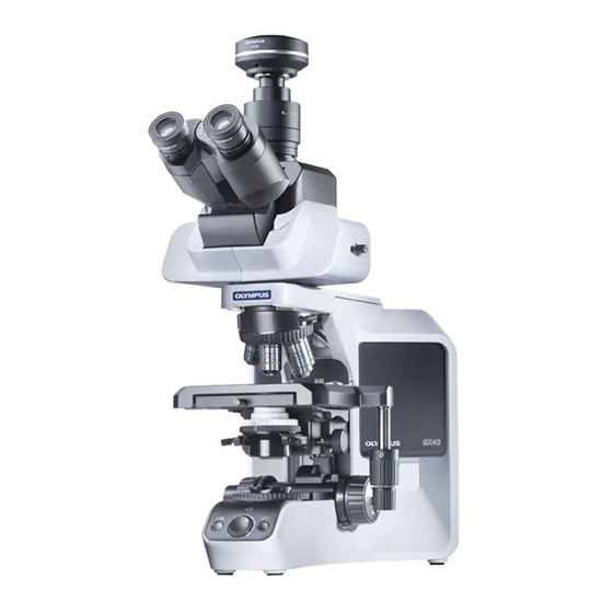
BX43
SYSTEM MICROSCOPE
This instruction manual is for the Olympus System Microscope Model BX43.
To ensure the safety, obtain optimum performance and to familiarize yourself fully with the use
of this microscope, we recommend that you study this manual thoroughly before operating the
microscope.
Retain this instruction manual in an easily accessible place near the work desk for future reference.
A X 7 8 5 1
Advertisement
Table of Contents

Related Manuals for Olympus BX43


Summary of Contents for Olympus BX43
- Page 1 BX43 SYSTEM MICROSCOPE This instruction manual is for the Olympus System Microscope Model BX43. To ensure the safety, obtain optimum performance and to familiarize yourself fully with the use of this microscope, we recommend that you study this manual thoroughly before operating the microscope.
- Page 2 Refer to your local Olympus distributor in EU for return and/or collection systems available in your country. NOTE: This equipment has been tested and found to comply with the limits for a Class A digital device, pursuant to Part 15 of the FCC Rules.
-
Page 3: Table Of Contents
BX43 CONTENTS Correct assembly and adjustments are critical for the microscope to exhibit its full performance. If you are going to assemble the microscope yourself, please read section 10, “ASSEMBLY” (pages 33 to 37) carefully. IMPORTANT -- Be sure to read this section for safe use of the equipment. --... - Page 4 5-6 Immersion Objectives ................................. 25 Using Immersion Objectives ....25 5-7 Objectives with Correction Collar ..........................25 CAMERA RECORDING ............26 Selecting the Camera Adapter System Chart ............26 Magnification TROUBLESHOOTING GUIDE 27-29 SPECIFICATIONS 30,31 OPTICAL CHARACTERISTICS (UIS2 Series) ASSEMBLY 33-37 -- See this section for the replacement of the light bulb.
-
Page 5: Important
4. Always use the power cord provided by Olympus. If no power cord is provided, please select the proper power cord by referring to the section “PROPER SELECTION OF THE POWER SUPPLY CORD” at the end of this instruction manual. -
Page 6: Safety Symbols
Rear panel position [Caution against high temperature] If a caution engraving or label is dirty or peeled off, contact Olympus for the replacement or other inquiry. Getting Ready 1. A microscope is a precision instrument. Handle it with care and avoid subjecting it to sudden or severe impact. -
Page 7: Maintenance And Storage
BX43 Maintenance and Storage 1. To clean the lenses and other glass components, simply blow dirt away using a commercially available blower and wipe gently using a piece of cleaning paper (or clean gauze). If a lens is stained with fingerprints or oil smudges, wipe it gauze slightly moistened with commercially available absolute alcohol. -
Page 8: Module Nomenclature
} The modules mentioned below show only the typical product names. As there are some products that are not mentioned but also applicable to this microscope, check the latest catalogues or consult Olympus. For the products marked “ * ”, also read their instruction manuals. -
Page 9: Controls
BX43 CONTROLS } If you have not yet assembled the microscope, read section 10, “ASSEMBLY” (pages 33 to 37). Interpupillary distance adjustment scale (Page 22) Condenser height adjustment knob (Page 12) Diopter adjustment ring (Page 22) Slide holder clamping lever... - Page 10 Main switch (Page 10) I : ON : OFF Pre-focusing lever (Page 16) LIM setting switch Fine adjustment knob (Page 13) (Page 16) LED brightness adjustment knob (Page 13) LIM indicator LIM ON-OFF switch (Page 13) ON: Lit (Green) OFF: Extinguished...
-
Page 11: Controls
BX43 Low Magnification Condenser Swing-out Condenser U-LC U-SC3 Top lens Auxiliary lens mounting tool (for BX53) Top lens swing-out knob Aperture iris diaphragm ring (Page 12) Auxiliary lens Condenser mount dovetail * The auxiliary lens is mounted on the lamp adapter when the U-LC is used. (Page 34) <<Modules for halogen lamp operation>>... -
Page 12: Flow Of Observation
FLOW OF OBSERVATION } When the LED lamp is used and the LIM is set, the LED brightness adjustment knob is defeated. } When the halogen bulb is used, set the LBD filter in the filter mount on the base (or in the U-FC filter cassette). (Controls Used) (Page) LED lamp... - Page 13 BX43 (trinocular tube only) } Copy the observation procedure pages on separate sheets and post it near your microscope.
-
Page 14: Simplified Observation Procedure
SIMPLIFIED OBSERVATION PROCEDURE 4-1 Basic Operation (Until Observation of Specimen) This section describes the basic operation of the microscope until the start of observation of a specimen. For the detailed operating procedure of each control, please read the description page specified below. Press the main switch of the microscope frame to “... -
Page 15: Microscope Adjustments (How To Improve The Observed Image)
BX43 Rotate the revolving nosepiece to engage the 10X objective in the light path. Rotate the coarse and fine adjustment knobs to bring the specimen into focus. (Details: Page 17) Rotate the stage knob to adjust the observation position. Now you can observe the magnified image of the specimen. To Fig. -
Page 16: Adjusting The Centering
Adjusting the Centering Place the specimen. Rotate the revolving nosepiece to select the 10X objective. Rotate the knobs to bring the specimen into focus. Rotate the knob to raise the condenser to its upper limit. Rotate the field iris diaphragm ring in the direction of the arrow so that the diaphragm image comes inside the field of view. -
Page 17: Using The Controls
Fig. 11 Setting the LIM Brightness (Fig. 12) } LIM stands for Light Intensity Manager. It is effective when the BX43-5RES revolving nosepiece with sensor and the U-LHLEDC LED lamp housing are used. } The desired brightness can be set per objective. Once the brightness for the objectives is set, selecting an objective adjusts the LED brightness automatically provided that the LIM ON-OFF switch @ is set to “ON”... -
Page 18: Using The Filters (Halogen Bulb Operation Only)
Using the Filters (Halogen Bulb Operation Only) } You can place a filter in the light path with either method. · Place a filter on the filter mount on the base and engage in the light path. (Page 14) · Insert a filter in the U-FC filter cassette, attach it on the filter mount and engage it in the light path by sliding the filter level. - Page 19 BX43 Using the Filter Cassette (Fig. 17) Usable Filters Applications 45LBD-IF* Color balancing filter 45-ND6, 45-ND25 Neutral density filter 45G-530, 43IF550-W45* Green B&W contrast filters 45O-560 Orange Up to three of the above filters can be loaded in the filter cassette. Moving Fig.
-
Page 20: Focusing Block
5-2 Focusing Block Focusing Controls The focusing block consists of the controls listed in the following table, which also describes the functions of the controls. Name Function Coarse adjustment Moves the focus position widely. knob Fine adjustment dial Fine adjusts the focus position. Fine adjustment Fine adjusts the focus position. -
Page 21: Knob
BX43 Replacing the Fine Adjustment Knob (Fig. 21) The fine adjustment knob has been attached on the right side CAUTION at the factory. } The fine adjustment knob is designed detachable to prevent interference with hand during manipulation of the X-and Y-axis knobs. -
Page 22: Stage
5-3 Stage Placing the Specimen } The dimensions of the slide glass should be 26 x 76 mm with thickness of 0.9 to 1.2 mm, and the cover glass should have thickness of 0.17 mm. } When observing very large specimens, remove the slide holder and place the specimen directly on the stage. -
Page 23: Knob Tension
BX43 Adjusting the X- and Y-Axis Knob Tension (Fig. 27) 1. Hold the X-axis knob @ and slide up the Y-axis knob 2 up to expose the adjustment knobs. 2. Turning the X-axis adjustment knob 3 or Y-axis adjustment knob | clockwise (in the direction of the arrow) increases the tension and counterclockwise decreases it. -
Page 24: Adjusting The X- And Y-Axis 4 Rotating The Stage
Rotating the Stage (Fig. 28) 1. Slightly loosen the stage clamping screw @. 2. The stage can be rotated both clockwise and counterclockwise by the stage clamping screw. A click may be heard and felt during rotation. However, this is CAUTION due to the construction of the substage and does not indicate a malfunction. -
Page 25: Observation Tube
BX43 5-4 Observation Tube Adjusting the Diopter When diopter adjustment rings are provided on both the left and right, it is possible to adjust the optimum vision for both the left and right eyes as described below. The diopter adjustment rings may be provided either on the eyepieces or the observation tube, and there is no problem even when the rings are not provided on both of them. -
Page 26: Disk
50% for camera * With the infrared trinocular tube, infrared observation up to 1000 nm is possible. For details, consult your Olympus representative. } The light path selector knob is located on the right side of the observation tube, but it can be removed and attached on the left side when the U-TTR is used. -
Page 27: Adjusting The Tilt
CAUTION The intermediate attachments that can be combined with the U-TTBI are limited. For details, please contact Olympus. With the U-TTLBI (Fig. 37) Fig. 37 The U-TTLBI is a Tilting, Telescopic, Lifting binocular tube with the following adjustment capabilities. -
Page 28: Using Eyepieces Incorporating A Micrometer
Using Eyepieces Incorporating a Micrometer } When the eyepieces in use incorporate a micrometer, the accuracy of the left-right focusing adjustment (diopter adjustment) can be improved further. 1. Looking into the right eyepiece with your right eye, turn the top of the eyepiece @ so that the micrometer in the field of view looks sharpest (Fig. -
Page 29: Immersion Objectives
BX43 5-6 Immersion Objectives Be sure to use the provided Olympus Immersion oil. CAUTION Using Immersion Objectives (Fig. 40) 1. Focus on the specimen with objectives in the order of lower-power to higher-power ones. 2. Before engaging the immersion objective, place a drop of provided immersion oil onto the specimen at the area to be observed. -
Page 30: Camera Recording
CAMERA RECORDING } Use a trinocular observation tube such as the U-TR30-2 or U-SWTR-2 when shooting the video or digital camera picture of the microscope images. The trinocular tube accepts a camera adapter (certain TV adapters necessitate a camera mount adapter). } Be sure to adjust the parfocality before using a camera adapter. -
Page 31: Troubleshooting Guide
Under certain conditions, performance of the unit may be adversely affected by factors other than defects. If problems occur, please review the following list and take remedial action as needed. If you cannot solve the problem after checking the entire list, please contact your local Olympus representative for assistance. Problem... - Page 32 Use immersion oil. with an oil immersion objective. Common Immersion oil contains bubbles. Remove the bubbles. Common Recommended immersion oil is Use an Olympus-designated not used. immersion oil. Common Dirt/dust on specimen. Clean it. Common Dirt/dust on condenser top lens.
- Page 33 BX43 Problem Lamp Cause Remedy Page Coarse adjustment will not go all Common Pre-focusing lever is locked at a Unlock pre-focusing lever. the way up. low position. Coarse adjustment will not go all Common Condenser holder is too low. Raise condenser holder.
-
Page 34: Specifications
Stroke per rotation: 0.1 mm (fine), 17.8 mm (coarse) Full stroke range: 25 mm Upper coarse adjustment limit stopper Tension adjustment on coarse focus adjustment knob. 4. Revolving nosepiece Type BX43-5RES U-D6RE 5-position revolving nosepiece with Universal 6-position revolving nosepiece readout function Attachable... - Page 35 BX43 Item Specification 7. Condenser Type U-LC U-AC2 U-SC3 U-AAC Low magnification Abbe Swing-out Achromat/ Aplanat Max. N . A . 0.75 1.10 1.40 2X - 60X 1.25X 10X - 100X Applicable objective (Widefield: FN 22) (Widefield: FN 22) (Widefield: FN 22)
-
Page 36: Optical Characteristics (Uis2 Series)
Mechanical tube length Oil: Oil immersion NOTE Iris: Iris diaphragm Refer to the latest catalogue or consult your local Olympus Field number (FN) representative for the updated information on the eyepieces Color band Cover glass thickness and objectives that can be combined with this microscope. -
Page 37: Assembly -- See This Section For The Replacement Of The Light Bulb
However, the assembly of the reflected light illuminator requires the use of the provided Allen wrench ( ) for clamping the internal screws (to ensure the performance, we recommend that you have your Olympus representative assemble or remove this module). - Page 38 10-2 Detailed Assembly Procedures Attaching the Auxiliary Lens for the U-LC (Fig. 42) Condenser } It is not necessary to attach the auxiliary lens if the condenser in use is other than the U-LC. 1. Attach the auxiliary lens @ provided with the condenser into the tip of the LED lamp housing C (U-LHLEDC) 2 or lamp housing adapter (U-LS30ADP) by screwing the lens in the direction of the arrow.
- Page 39 BX43 Installing the Halogen Bulb (Fig. 45) Use only the designated bulb 6V30WHAL (PHILIPS 5761). 1. Holding the bulb 2 a piece of gauze, insert the bulb pins 3 straight and fully into the pin holes | on the lamp socket.
- Page 40 } As shown in Fig. 49, connect to the connector by letting the cable into the cable holder (attached with BX43-5RES) attached to the rear panel. Fig. 49 Attaching the Condenser (Fig.
- Page 41 AC adapter may cause malfunction. Fig. 52 Attaching the Power Cord Always use the power cord provided by Olympus. If no power CAUTION cord is provided with the microscope, please select the proper power cord by referring to section “PROPER SELECTION OF THE POWER SUPPLY CORD”...
-
Page 42: Halogen Lamp Socket Inspection Sheet
{ If there is any ( ) mark noted, immediately stop use of the product, and consult Olympus for detailed inspections or replace the lamp socket. { If you detect an abnormality other than that listed below or with other Olympus product, also stop the use of the product and contact Olympus for detailed inspections. -
Page 43: Proper Selection Of The Power Supply Cord
If no power supply cord is provided, please select the proper power supply cord for the equipment by referring to “ Specifications ” and “ Certified Cord ” below: CAUTION: In case you use a non-approved power supply cord for Olympus products, Olympus can no longer warrant the electrical safety of the equipment. - Page 44 Table 2 HAR Flexible Cord APPROVAL ORGANIZATIONS AND CORDAGE HARMONIZATION MARKING METHODS Alternative Marking Utilizing Printed or Embossed Harmoni- Black-Red-Yellow Thread (Length zation Marking (May be located of color section in mm) Approval Organization on jacket or insulation of internal wiring) Black Yellow...
- Page 45 MEMO...
- Page 46 MEMO...
- Page 48 Shinjuku Monolith, 3-1, Nishi Shinjuku 2-chome, Shinjuku-ku, Tokyo, Japan Wendenstrasse 14-18, 20097 Hamburg, Germany 3500 Corporate Parkway, Center Valley, Pennsylvania 18034-0610, U.S.A. 491B River Valley Road, #12-01/04 Valley Point Office Tower, Singapore 248373 31 Gilby Road, Mount Waverley, VIC., 3149, Melbourne, Australia 5301 Blue Lagoon Drive, Suite 290 Miami, FL 33126, U.S.A.