Table of Contents
Advertisement
INSTRUCTIONS
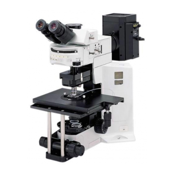
BX51WI
FIXED-STAGE UPRIGHT
MICROSCOPE
This instruction manual is for the Olympus Fixed-Stage Upright Microscope Model BX51WI. To
ensure the safety, obtain optimum performance and to familiarize yourself fully with the use of
this microscope, we recommend that you study this manual thoroughly before operating the
microscope. Retain this instruction manual in an easily accessible place near the work desk for
future reference.
A X 7 6 5 7
Advertisement
Table of Contents

Related Manuals for Olympus BX51WI


Summary of Contents for Olympus BX51WI
- Page 1 FIXED-STAGE UPRIGHT MICROSCOPE This instruction manual is for the Olympus Fixed-Stage Upright Microscope Model BX51WI. To ensure the safety, obtain optimum performance and to familiarize yourself fully with the use of this microscope, we recommend that you study this manual thoroughly before operating the microscope.
-
Page 3: Table Of Contents
BX51WI CONTENTS Correct assembly and adjustments are critical for the microscope to exhibit its full performance. If you are going to assemble the microscope yourself, please read Chapter 9, “ASSEMBLY” (pages 36 to 42) carefully. For the modules provided with instruction manuals, also read the assembly procedures in their instruction manuals. - Page 4 OTHER OBSERVATION METHODS 19-30 5-1 Differential Interference Contrast Observation ................19-23 Attaching the Analyzer Attaching the Polarizer Attaching the DIC Prisms (for Revolving Nosepiece) Attaching the DIC Prisms (for Condenser) Adjusting the Polarizer Position (except the U-UCD8) Observation Method 5-2 Reflected Light Fluorescence Observation ....................24 5-3 Infrared Light (IR)/Differential Interference Contrast (DIC) Observation ....
- Page 5 2. The U-SWTR-3 super-widefield observation tube (FN 26.5) cannot be used with the BX51WI microscope. 3. The BX51WI microscope can be used with an intermediate attachment (such as a BX-URA2 or BX-RFA reflected light illuminator, U-ECA or U-CA magnification changer, etc.).
- Page 6 6. When the XLUMPlanFl20XW objective is used, only the U-TV1X-2, U-TVCAC, U-PMTVC2XIR or U-PMTVC4XIR TV adapter can be used. 7. Do not attempt to remove or loosen the click springs and screws. Otherwise, Olympus can no longer warrant the performance of the microscope.
- Page 7 }The modules shown below are only the representative modules. As there are other modules which can be combined with the microscope but are not shown below, please also refer to the latest Olympus catalogues or your dealer. Transmitted Arm BX-ARM or Reflected Light Fluorescence Illuminator ·...
- Page 8 CONTROLS }If you have not yet assembled the microscope, read Chapter 9, “ASSEMBLY” (pages 36 to 42). Light path selector knob (Page 15) Interpupillary distance scale (Page 14) Reflected light mercury lamp housing (See the separately provided instruction manual.) Diopter adjustment ring (Page 14) Reflected light fluorescence illuminator...
- Page 9 BX51WI * Accepts the combination of a Polarizer rotating dials Filter Turret (Page 23) polarizer push ring and a 32 mm filter. The thickness should be no Polarizer positions (Page 19)* Slider insertion/removal Accepts the 32PO or 32POIR. more than 6 mm.
- Page 10 Swinging Revolving Nosepiece WI-SRE3 Swing lever Confocality correction washers (Kinds of thickness: 10, 30 and 50 μm; three washers per kind) DIC mount hole (Page 20) Centering screw UIS2 (UIS) objective mount Centering knob screws Long-WD Universal Condenser WI-UCD Aperture iris diaphragm lever (Page 17) Quarter-wave plate clamping knob Optical element index...
- Page 11 BX51WI Differential Interference Contrast Prisms (For Condenser) }The WI-UCD condenser accepts two large and two small DIC prisms while the WI-DICD condenser accepts one large or small DIC prism. When selecting the brightfield (BF) light path using the WI-UCD, leave one DIC prism (large) mount position empty.
- Page 12 TRANSMITTED LIGHT BRIGHTFIELD OBSERVATION PROCEDURE }The following flow shows the operating procedure for the transmitted light brightfield observation which is the basic obser- vation method of this microscope. The operating procedures for DIC observation, fluorescence DIC observation and IR DIC observation will be described separately in Chapter 5, “OTHER OBSERVATION METHODS”...
- Page 13 BX51WI ‰ Š … ƒ ‹Œ™ † ³ † š † ² ‡ ‡ Used only when the hand switch is not connected } Make a photocopy of the observation procedure pages and post it near your microscope.
-
Page 14: Using The Controls
USING THE CONTROLS 4-1 Microscope Base, Power Supply Unit (TH4) Controlling the Light Intensity (TH4) (Figs. 2 & 3) ³ }See the separately provided instruction manual for details. 1. Make sure that the light intensity control knob @ is set to MIN (minimum voltage), then set the main switch ²... -
Page 15: Focusing Block
BX51WI 4-2 Focusing Block Using the Pre-focusing Lever (Fig. 5) }The pre-focusing lever prevents collision between the specimen and objective and simplifies the focusing operation. After bringing the specimen into approximate focus with the coarse adjustment knob, turn the pre-focusing lever @ in the direction of the arrow to lock it. Hereafter, the lower limit of the coarse adjustment will be limited at the position where the lever is locked. -
Page 16: Stage (Ix-Svl2)
4-3 Stage (IX-SVL2) Placing the Specimen (Fig. 8) 1. Place the specimen on the center of the stage. }The optional stage center plate (IX-CP50) makes it possible to observe a wide range of a big petri dish, etc. (Central hole diameter: 50 mm) Fig. -
Page 17: Using The Light Shield Sheet
(Fig. 12) # The light shield sheet provided with the reflected light fluorescence illuminator is too small to be used with the BX51WI. Always use the light shield sheet provided with the BX51WI microscope frame. }During fluorescence observation using a low-magnification objective, the fluorescence image may be deteriorated due to light reflected from the condenser or the surroundings. -
Page 18: Observation Tube
4-5 Observation Tube Adjusting the Interpupillary Distance (Fig. 15) While looking through the eyepieces, adjust for binocular vision until the left and right fields of view coincide completely. The index dot · indicates the interpupillary distance. }Note your interpupillary distance so that it can be quickly duplicated. Fig. -
Page 19: Using Eyepiece Micrometer Disks
BX51WI Using Eyepiece Micrometer Disks (Fig. 19) Eyepiece micrometer disks can be inserted into the WHN10X-H (or WHN10X) eyepieces. However, if the eyepiece does not have the helicoid adjustment facility and your eyesight is poor, you may have difficulties in focusing on the ²... -
Page 20: Condenser
4-6 Condenser Centering the Condenser (Figs. 21 & 22) 1. Set the aperture iris diaphragm lever @ to the open position. (Fig. 22) 2. Set the field iris diaphragm ring ² to the open position ( ¦). (Fig. 21) 3. Focus on the specimen using the 10X objective. 4. -
Page 21: Oblique Illumination (Wi-Obcd)
BX51WI Aperture iris Aperture Iris Diaphragm 70-80% diaphragm image · The aperture iris diaphragm determines the numerical aperture of the 30-20% illumination system. Matching the numerical aperture of the illumination system with that of the objective provides better image resolution and contrast, and also increases the depth of focus. -
Page 22: Immersion Objectives
4-7 Immersion Objectives Using Water Immersion Objectives (Figs. 26 & 27) }When the UMPlanFLN series, LUMPlanFLN series or XLUMPlanFl20XW objective is used, cultured tissue specimens which are often very thick can be observed by immersing the specimen, objective front lens and manipulator extremity in a medium with the same refractive index (water). -
Page 23: Other Observation Methods
2. Remove the cover to expose the polarizer and remove it together with the frame. (Retain the removed polarizer carefully for future use with a microscope other than the BX51WI. 3. Attach the polarizer cover to the original position. Fig. 30... -
Page 24: Attaching The Dic Prisms (For Revolving Nosepiece)
Attaching the DIC Prisms (for Revolving Nosepiece) ² (Fig. 31) ³ }The DIC prisms for use in the revolving nosepiece include the WI-DICTHRA2 (high-resolution type) and WI-DICT2 (middle-contrast type). The revolving nosepieces in which a DIC prism can be inserted are the WI-SRE3 and WI-SNPXLU2. - Page 25 BX51WI With the WI-UCD Condenser (Figs. 32-34) ² }When selecting the brightfield (BF) light path using the WI-UCD, leave one DIC prism (large) mount position empty. 1. Remove the WI-UCD condenser from the microscope frame. 2. Remove the condenser cover @ by loosening the retaining screws ²...
-
Page 26: Adjusting The Polarizer Position (Except The U-Ucd8)
With the WI-DICD Condenser (Fig. 35) ³ }The WI-DICD should be attached after completing the polarizer position ² as described in item 1. Remove the WI-DICD condenser from the microscope frame. 2. Remove the two clamping screws @ using the Allen screwdriver provided with the microscope, then place the top of the condenser upside down. -
Page 27: Observation Method
4. Remove the eyepiece from the eyepiece sleeve, look into the sleeve, turn the polarizer rotation dial ² so that the black interference stripe (Fig. 37) is darkest, and tighten the clamping knob ³. 5. Engage an objective (as low-magnification as possible) in the light path, attach the condenser and bring the specimen surface into focus. -
Page 28: Reflected Light Fluorescence Observation
(See pages 10 and 22.) 2. To reduce the influence of heat on the specimen, stop down the field iris diaphragm of the BX51WI microscope as small as possible. However, note also that the contrast may sometimes be improved by circumscribing the field iris image with... - Page 29 BX51WI 3. To enable IR observation, the following modules should be replaced with those based on the IR specifications. IR TV camera Video contrast device such as TV adapter (Note) the ARGUS10, 20 by Hamamatsu Photonics, monochrome video monitor Trinocular tune...
- Page 30 Attaching the IR Modules (Figs. 40 & 41) Thermal Reflection Filter 45SCF 1. Remove the collector lens of the U-LH100IR lamp housing @ by loosen- ing the 3 clamping screws ² with an Allen wrench (width across flats of 2.5 mm). ²...
-
Page 31: Dic Observation Using Ir
BX51WI DIC Observation Using IR Since IR light is harmful to your eyes, use the monitor observation whenever possible even in adjustments. 1. First, perform adjustments for DIC observation without using IR. }Do not mount the IR filter and see Section 5-1, “Differential Interference Contrast Observation” on page 19. -
Page 32: Macro Reflected Light Fluorescence Observation
5-4 Macro Reflected Light Fluorescence Observation }The macro reflected light fluorescence observation makes possible bright, low-magnification fluorescence observation by combining low-magnification fluorescence mirror units and fluorescence objective. Introduction 1. For the low-magnification fluorescence observation, use a low-magnification fluorescence mirror units. The increased observation beam diameter of the fluorescence mirror units brightens the fluorescence by about 25%. - Page 33 BX51WI Attaching the Modules (Figs. 42 & 43) Low-Magnification Fluorescence Mirror Units }Select the suitable mirror units for purpose of observation by referring to page 30. }If you want to fabricate optional mirror units, see page 30. · Mount the mirror units as indicated in the instruction manual of your reflected light fluorescence system.
-
Page 34: Filter Characteristics Of Fluorescence Mirror Units
Filter Characteristics of Fluorescence Mirror Units Excitation Mirror Unit Dichroic Mirror Excitation Filter Barrier Filter Application Method U-MGFP/XL BA510IF For EGFP, S65T, RSGFP. DM505 BP460-490 (U-MGFPA/XL is for fluorochrome separation.) U-MGFPA/XL BA510-550 1. IB excitation (wide bandwidth) U-MGFP/XL 2. IB excitation (wide bandwidth) U-MGFPA/XL Wavelength (nm) Wavelength (nm) -
Page 35: Troubleshooting Guide
Under certain conditions, performance of the microscope may be adversely affected by factors other than defects. If problems occur, please review the following list and take remedial action as needed. If you cannot solve the problem after checking the entire list, please contact your local Olympus representative for assistance. Problem... - Page 36 Problem Cause Remedy Page f ) Visibility of observed image is poor. The specimen such as a brain slice is Fix it correctly. – · Image is not sharp. fixed poorly. · Contrast is poor. Bubbles attached to the objective front Remove the bubbles.
- Page 37 BX51WI Problem Cause Remedy Page 3. Coarse/Fine Adjustment Knobs a) Coarse adjustment knob is too The rotation tension adjustment ring is Fully loosen the ring by turning it coun- heavy to rotate. secured tightly. terclockwise. The pre-focusing lever is locked.
-
Page 38: Specifications
SPECIFICATIONS Item Specification 1. Optical system UIS2 (UIS) (Universal Infinity System) optical system (Infinity correction) 2. Illumination system Transmitted Kohler illumination built in (FN 22) 12 V, 100 W long-life halogen bulb (pre-centered) Average life time: Approximately 2000 hr. when used as directed. Light intensity voltage range: 2.5 12.6 V DC (continuously variable), 8.4 A max. -
Page 39: Optical Characteristics
Magnification Number of aperture Mechanical tube length FN (Field number) NOTE Refer to the latest catalogue or consult your local Olympus Color band Water immersion indicator (white) representative for the updated information on the eyepieces and objectives that can be combined with this microscope. -
Page 40: Assembly
The module numbers shown in the following diagram are merely the typical examples. For the modules with which the module numbers are not given, please consult your Olympus representative or the latest catalogues. # When assembling the microscope, make sure that all parts are free of dust and dirt, and avoid scratching any parts or touching glass surfaces. - Page 41 BX51WI Revolving Arm, Revolving Nosepiece, Objectives Light shielding tube Light shielding tube Reflected light fluorescence (transmitted light arm adapter) illuminator Transmitted light arm BX-URA2 BX-ARM BX-RFA Light shielding tube The revolving nosepiece clamping screw is not used. Revolving arm Sliding revolving nosepiece...
- Page 42 9-2 Detailed Assembly Procedures }When performing observation on a desktop, attach the provided rubber feet (x 4) to the front (x 2) and rear (x 2) parts on the bottom of the base. ³ Attaching the Revolving Arm (Fig. 44) 1.
- Page 43 BX51WI 3. Engage the objective on the back side in the light path. Adjust focusing, read the scale indication of the fine adjustment knob and obtain the difference from the value read in step 2 above. … ƒ 4. The objective to use the washer is determined by the rotation direction of ³...
- Page 44 }The magnetic support plates ² are most effective when they are at- tached symmetrically at positions by about 15 mm above the BX51WI indications. 3. Fix the waterproof cover using magnets ³. }When the cross stage is used, the stage mounting screw holes (x 4 on the front and rear) are hidden by the waterproof cover.
- Page 45 BX51WI Attaching the Halogen Lamp Housing (Figs. 51-54) Attaching the Halogen Bulb }The applicable lamp bulb model is the 12V100WHAL-L (PHILIPS 7724) or the 12V50WHAL-L (LIFE JC). ² 1. Fully loosen the clamping screw @ at the top of the lamp housing using the Allen screwdriver provided with the microscope frame.
- Page 46 Attaching the Cross Stage (Figs. 55 & 56) † }When using a commercially marketed bridge stage, attach it by referring to its instruction manual. 1. Align the two WI-FSH fixed stage adapters @ with the front of the micro- scope base and clamp the adapters by tightening the hex-socket screws from the bottom side using the Allen wrench provided with the micro- scope frame.
-
Page 47: Proper Selection Of The Power Supply Cord
If no power supply cord is provided, please select the proper power supply cord for the equipment by referring to “ Specifications ” and “ Certified Cord ” below: CAUTION: In case you use a non-approved power supply cord for Olympus products, Olympus can no longer warrant the electrical safety of the equipment. - Page 48 Table 2 HAR Flexible Cord APPROVAL ORGANIZATIONS AND CORDAGE HARMONIZATION MARKING METHODS Alternative Marking Utilizing Printed or Embossed Harmoniza- Black-Red-Yellow Thread (Length tion Marking (May be located on Approval Organization of color section in mm) jacket or insulation of internal wir- ing) Black Yellow...
-
Page 49: Lamp Housing Inspection Sheet
{If there is any ( ) mark noted, immediately stop use of the product, and contact Olympus for detailed inspections or replace the lamp housing. {If you detect an abnormality other than that listed below or with other Olympus product, also stop the use of the product and contact Olympus for detailed inspections. - Page 50 MEMO...
- Page 52 Shinjuku Monolith, 3-1, Nishi Shinjuku 2-chome, Shinjuku-ku, Tokyo, Japan Wendenstraße 14-18, 20097 Hamburg, Germany 3500 Corporate Parkway, P.O. Box 610, Center Valley, PA 18034-0610, U.S.A. One Corporate Drive, Orangeburg, NY 10962, U.S.A. 491B River Valley Road, #12-01/04 Valley Point Office Tower, Singapore 248373 31 Gilby Road, Mount Waverley, VIC., 3149, Australia 5301 Blue Lagoon Drive, Suite 290 Miami, FL 33126, U.S.A.