Table of Contents
Advertisement
Quick Links
Download this manual
See also:
User Manual
Advertisement
Chapters
Table of Contents
Troubleshooting

Related Manuals for Toshiba Portege 2000


Summary of Contents for Toshiba Portege 2000
- Page 1 Toshiba Personal Computer Portege 2000 Maintenance Manual TOSHIBA CORPORATION File Number 960-333...
- Page 2 © 2002 by Toshiba Corporation. All rights reserved. Under the copyright laws, this manual cannot be reproduced in any form without the prior written permission of Toshiba. No patent liability is assumed with respect to the use of the information contained herein.
- Page 3 Preface This maintenance manual describes how to perform hardware service maintenance for the Toshiba Personal Computer Portege 2000, referred to as Portege 2000 in this manual. The procedures described in this manual are intended to help service technicians isolate faulty Field Replaceable Units (FRUs) and replace them in the field.
- Page 4 The manual is divided into the following parts: Chapter 1 Hardware Overview describes the Portege 2000 system unit and each FRU. Chapter 2 Troubleshooting Procedures explains how to diagnose and resolve FRU problems. Chapter 3 Test and Diagnostics describes how to perform test and diagnostic operations for maintenance service.
- Page 5 Text that you are instructed to type in is shown in the boldface type below: DISKCOPY A: B: The display Text generated by the Portege 3410CT/3440CT that appears on its display is presented in the type face below: Format complete System transferred Portege 2000 Maintenance Manual (960-333)
-
Page 6: Table Of Contents
Main Board Troubleshooting ...................2-15 USB 3.5” FDD Troubleshooting................2-27 1.8” HDD Troubleshooting ..................2-30 Keyboard Troubleshooting..................2-35 Display Troubleshooting ..................2-36 Touch Pad.........................2-38 2.10 Modem ........................2-39 2.11 LAN..........................2-41 2.12 Sound........................2-43 2.13 SD card slot ......................2-45 2.14 Wireless LAN Troubleshooting ................2-46 Portege 2000 Maintenance Manual (960-333) - Page 7 3.19 Log Utilities......................3-44 3.20 Running Test ......................3-46 3.21 Floppy Disk Drive Utilities ..................3-48 3.22 System Configuration....................3-54 Chapter 4 Replacement Procedures Overview ........................4-1 Battery pack/PC card....................4-8 Memory Module.......................4-11 HDD .........................4-14 Keyboard/Bottom cover ...................4-17 Speaker/RTC battery ....................4-22 Portege 2000 Maintenance Manual (960-333)
- Page 8 Appendix B Board Layout....................B-1 Appendix C Pin Assignment ..................C-1 Appendix D Keyboard Scan/Character Codes..............D-1 Appendix E Key Layout....................E-1 Appendix F BIOS/KBC/EC Update................F-1 Appendix G Reliability ....................G-1 Appendix H Key FD .......................H-1 viii Portege 2000 Maintenance Manual (960-333)
-
Page 9: Chapter 1 Hardware Overview
Chapter 1 Hardware Overview... - Page 10 1 Hardware Overview Hardware Overview 1-ii Portege 2000 Maintenance Manual (960-333)
- Page 11 Keyboard ........................1-11 TFT Color Display ....................1-12 1.4.1 LCD Module..................1-12 1.4.2 FL Inverter Board ................1-13 Power Supply ......................1-14 Batteries........................1-15 1.6.1 Main Battery ..................1-15 1.6.2 Battery Charging Control ..............1-16 1.6.3 RTC battery ..................1-16 AC Adapter ......................1-17 Portege 2000 Maintenance Manual (960-333) 1-iii...
- Page 12 FL inverter board specifications..............1-13 Table 1-5 Power supply output specifications..............1-14 Table 1-6 Battery specifications ...................1-15 Table 1-7 Time required for charges of main battery...........1-16 Table 1-8 RTC battery charging/data preservation time ..........1-16 Table 1-9 AC adapter specifications................1-17 1-iv Portege 2000 Maintenance Manual (960-333)
-
Page 13: Features
Three-mode 3.5 inch USB FDD supporting 720KB, 1.2MB and 1.44MB formats is prepared as option. Display Built-in 12.1 inch, 262,144 colors, XGA (1024×768 dots), thin type low temperature poly- silicon TFT color display. Video controller is included in North Bridge chip. Supported via an RGB connector Portege 2000 Maintenance Manual (960-333) - Page 14 ITU-TV.90. The transfer rates are 56 Kbps for data reception, 33.6 Kbps for data transmission, and 14,400 bps for fax transmission. However, the actual speed depends on the line quality. The RJ11 modem jack is used to accommodate a telephone line. The internal LAN supports 10BASE-T and 100BASE-TX. Portege 2000 Maintenance Manual (960-333)
- Page 15 Wireless LAN The internal wireless LAN supports Mini PCI Type III(802.11B) made by Agere. FIR(Fast Serial InfraRed) communication port Fast Serial InfraRed(FIR) communication port supports IrDA1.1. 1.15Mbps or 4Mbps wireless communication is realized by this FIR. Portege 2000 Maintenance Manual (960-333)
-
Page 16: Figure 1-1 Front Of The Computer
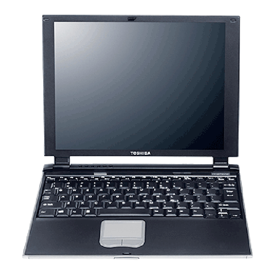
Figure 1-1 shows the front of the computer and Figure 1-2 shows the system units configuration. Figure 1-1 Front of the computer Outer Microphone Headphone Docking I/F RTC Battery Speaker Battery AC Adapter Network SD Card Debug Port Intouch PC Card Keyboard Pad Figure 1-2 System units configuration Portege 2000 Maintenance Manual (960-333) -
Page 17: Figure 1-3 System Block Diagram
1.1 Features 1 Hardware Overview Figure 1-3 shows the system block diagram. Figure 1-3 System Block Diagram Portege 2000 Maintenance Manual (960-333) - Page 18 − 8KB used for password security − 16KB used for booting − 64KB used for LAN − 32KB are reserved • 5.0V operation • Access time : 120 ns or 90 ns • Data transfer: 8-bit Portege 2000 Maintenance Manual (960-333)
- Page 19 − 352-ball (27mm x 27mm) BGA package VGA controller Included in North Bridge PC card controller (YEBISU3S) • PCI interface (PCI Reision2) • Chipset interface Intel serial interrupt • CardBus/PC Card controller (Yenta Version2.2) :2 slots Portege 2000 Maintenance Manual (960-333)
- Page 20 1 Hardware Overview 1.1 Features Parallel power supply control (Toshiba style) and serial power supply control (Texas Instruments style) • SD card controller (SDHC Ver.1.2) • SDIO card controller (Ver.1.0) • SmertMedia controller (SMHC Ver.01/SMIL 1.0) • SmertCard interface • SIO controller •...
-
Page 21: Inch Hard Disk Drive
Figure 1-4 shows a view of the 1.8-inch HDD and Tables 1-1 and 1-2 list the specifications. Figure 1-4 1.8-inch HDD Table 1-1 1.8-inch HDD dimensions Standard value Parameter TOSHIBA MK2003GAH Outline Width (mm) 54.0 dimensions Height (mm) Depth (mm) 78.5 Weight (g) 62 (MAX) Portege 2000 Maintenance Manual (960-333) - Page 22 Data transfer speed (Mbits/s) 115.6 to 204.4 Interface transfer rate (MB/s) Track density Track/mm(TPI) 2237 (56.8K) max. Bit/mm 24.4K(621K) max. Access time (msec) Track to track Average time Max seek Start time (sec) 3.5 (Typ.) 20 (Max.) 1-10 Portege 2000 Maintenance Manual (960-333)
-
Page 23: Keyboard
The keyboard is mounted 84(US)/85(UK) keys that consist of character key and control key, and in conformity with JIS. The keyboard is connected to membrane connector on the system board and controlled by the keyboard controller. See Appendix E about a layout of the keyboard. Portege 2000 Maintenance Manual (960-333) 1-11... -
Page 24: Tft Color Display
Table 1-5 shows list the specifications. Table 1-3 LCD module specifications (12.1 TFT) Item Specifications VF2095P01 Number of Dots 1024×768 Dot spacing (mm) 0.24(H) x 0.24(V) Display range (mm) 245.76(H) x 184.32(V) Outline 267.4(w) x 197.5(H) x 5.55Max(D) dimensions 1-12 Portege 2000 Maintenance Manual (960-333) -
Page 25: Fl Inverter Board Specifications
The FL inverter board supplies a high frequency current to illuminate the LCD module FL. Table 1-4 lists the FL inverter board specifications. Table 1-4 FL inverter board specifications Item Specifications UA2040P02 Input Voltage DC 5 Output Voltage Current MAX (mA) 4.22 Current MIN (mA) 0.412 Portege 2000 Maintenance Manual (960-333) 1-13... -
Page 26: Power Supply
MDC(Asky), LAN(REL8139CL) B2R5V M1644M, CLKGen(ICS94258) 2.5±5% CPU(ADM11032), M1535, LCD, BIOS(TC58F401FT), 3.30±5% RTC(bq3285LD), Sound(YMF753),Mini PCI(Wireless LAN) M1644, PCMCIA slot1 5.00±5% M1535, FLINV, YEBISUSS, Sound(YMF753), HDD, CD-R/W, USB, 5.00±5% Sound(MMM1517) SNDVCC 5.00±5% CPU(MAX6501), SB(M1535) 5.00±5% 1-14 Portege 2000 Maintenance Manual (960-333) -
Page 27: Batteries
1.6.1 Main Battery The main battery is the primary power supply for the computer when the AC adapter is not connected. In resume (instant recovery) mode, the main battery maintains the current status of the computer. Portege 2000 Maintenance Manual (960-333) 1-15... - Page 28 Table 1-8 lists the battery charging time and data preservation times. Table 1-8 RTC battery charging/data preservation time Time Charging AC adapter or main battery in use 8 hours (approx ) Data preservation time (when fully charged) 1 month 1-16 Portege 2000 Maintenance Manual (960-333)
-
Page 29: Ac Adapter
Table 1-9 lists the AC adapter specifications. Table 1-9 AC adapter specifications Parameter Specification Input voltage AC 90 to 264V Input frequency 47Hz/63Hz Input current(MAX) 1.2A (100VAC) Output voltage DC 15V Output current 3.0A Portege 2000 Maintenance Manual (960-333) 1-17... - Page 30 1 Hardware Overview 1.7 AC Adapter 1-18 Portege 2000 Maintenance Manual (960-333)
-
Page 31: Chapter 2 Troubleshooting Procedures
Chapter 2 Troubleshooting Procedures... - Page 32 2 Troubleshooting Procedures 2-ii Portege 2000 Maintenance Manual (960-333)
- Page 33 Procedure 4 Diagnostic Test Program Execution Check ......2-33 Procedure 5 Connector Check and Replacement Check ......2-34 Keyboard Troubleshooting..................2-35 Procedure 1 Diagnostic Test Program Execution Check ......2-35 Procedure 2 Connector Check and Replacement Check ......2-35 Portege 2000 Maintenance Manual (960-333) 2-iii...
- Page 34 Check on Windows ..............2-54 Procedure 2 Connector/ Replacement Check ...........2-45 2.14 Wireless LAN Troubleshooting ................2-46 Procedure 1 Trancemitting-Receiving Check ..........2-46 Procedure 2 Antennas’ Connection Check..........2-47 Procedure 3 Antenna Check ..............2-48 Procedure 4 Replacement Check..............2-50 2-iv Portege 2000 Maintenance Manual (960-333)
-
Page 35: Table
Antenna Test jig ...................2-48 Tables Table 2-1 Battery icon ....................2-7 Table 2-2 DC IN icon .....................2-7 Table 2-3 D port status ....................2-20 Table 2-4 FDD error code and status................2-28 Table 2-5 Hard disk drive error code and status............2-33 Portege 2000 Maintenance Manual (960-333) - Page 36 2 Troubleshooting Procedures 2-vi Portege 2000 Maintenance Manual (960-333)
-
Page 37: Troubleshooting
8. Wraparound connector for PC card 9. Tester 10. External CRT 11. External USB Keyboard 12. External USB mouse 13. Headphone 14. Microphone 15. RJ-11 connector checker LED 16. LAN wraparound connector 17. Speaker with S/PDIF input terminal Portege 2000 Maintenance Manual (960-333) -
Page 38: Troubleshooting Flowchart
Make sure that Toshiba Windows 98,2000 or XP is installed on the hard disk. Non- Toshiba operating systems can cause the computer malfunction. Make sure all optional equipment is removed from the computer. Make sure the USB FDD is empty. - Page 39 2.8. If the “Password=” message displays, type the password. Perform the 1.8” HDD Are Toshiba Windows 98,2000 or Troubleshooting Procedures XP being loaded? in section 2.6. Figure 2-1 Troubleshooting flowchart (1/2) Portege 2000 Maintenance Manual (960-333)
- Page 40 Perform each test of the diagnostic test. After conforming which diagnostic Is an error test has detected an error, perform detected by any of the the appropriate procedures as diagnostic test? outlined below. System is normal. Figure 2-2 Troubleshooting flowchart (2/2) Portege 2000 Maintenance Manual (960-333)
- Page 41 4. If an error is detected on the keyboard test, perform the Keyboard Troubleshooting Procedures in Section 2.7. 5. If an error is detected on the display test, perform the Display Troubleshooting Procedures in Section 2.8. Portege 2000 Maintenance Manual (960-333)
-
Page 42: Power Supply Troubleshooting
Procedure 1 and continue with the other Procedures as instructed. The procedures described in this section are: Procedure 1: Power supply icon Check Procedure 2: Error Code Check Procedure 3: Connection Check Procedure 4: Quick Charge Check Procedure 5: Replacement Check Portege 2000 Maintenance Manual (960-333) - Page 43 Blinks orange Power supply malfunction * 3 Doesn’t light Any condition other than those above. *3 When the power supply controller detects a malfunction, the DC IN icon blinks orange. It shows an error code. Portege 2000 Maintenance Manual (960-333)
- Page 44 If the DC IN icon does not light, go to Procedure 3. Check 3 If the battery icon does not light orange or green, go to Procedure 4. CAUTION: Use a recommended AC adapter (ADP-45W) only. Portege 2000 Maintenance Manual (960-333)
- Page 45 Main battery charge current is over 4.95A. Main battery discharge current is over 0.5A when there is no load. Main battery charge current is over 2.3A. Abnormal current has been sensed 0[A]. Main battery charge current is over 0.3A. Portege 2000 Maintenance Manual (960-333)
- Page 46 E3V voltage is 2.81V or less when the computer is booting up. E3V voltage is abnormal while the computer is suspended. E3V voltage is abnormal during shutdown (CV support) E3V voltage is 2.81V or less at power-on (CV support) 2-10 Portege 2000 Maintenance Manual (960-333)
- Page 47 EMV voltage is 1.53V or less when the computer is powered on. EMV voltage is 1.53V or less when the computer is booting up. EMV voltage is abnormal while the computer is suspended. EMV voltage is over 1.53V when the computer is powered off. Portege 2000 Maintenance Manual (960-333) 2-11...
- Page 48 Connect a new AC adapter and AC power cord. If the error still exists, go to Procedure 5. Check 3 In the case of error code 21h: Go to Procedure 3. Check 4 For any other errors, go to Procedure 5. 2-12 Portege 2000 Maintenance Manual (960-333)
- Page 49 If the battery pack is still not charged, go to Check 5. Check 5 Replace the battery pack with a new one. If the battery pack is still not charged, go to Procedure 5. Portege 2000 Maintenance Manual (960-333) 2-13...
- Page 50 To disassemble the computer, follow the steps described in Chapter 4. Check 1 Replace the AC adapter with a new one. If the AC adapter is still not functioning properly, perform Check 2. Check 2 Replace the main board with a new one. 2-14 Portege 2000 Maintenance Manual (960-333)
-
Page 51: Main Board Troubleshooting
The procedures described in this section are: Procedure 1: Message Check Procedure 2: Debug port (D port) Check on Boot Mode Procedure 3: Diagnostic Test Program Execution Check Procedure 4: Replacement Check Portege 2000 Maintenance Manual (960-333) 2-15... - Page 52 The following error message appears when data stored in RAM under the resume function is lost because the battery has become discharged or the main board is damaged. Go to Procedure 3. WARNING: RESUME FAILURE. PRESS ANY KEY TO CONTINUE. 2-16 Portege 2000 Maintenance Manual (960-333)
- Page 53 (16) PIC #1 ERROR (17) PIC #2 ERROR (18) KBC ERROR (19) HDC ERROR (20) HDD #0 ERROR (21) HDD #1 ERROR (22) NO FDD ERROR (23) FDC ERROR (24) TIMER INTERRUPT ERROR (25) RTC UPDATE ERROR Portege 2000 Maintenance Manual (960-333) 2-17...
- Page 54 3. Connect the RS-232C cross-cable to the PC that displays the results. RS232C cross-cable Debug port test cable PC that displays Test board PJ325 Main board the test results 4. Boot the computer in MS-DOS mode. 2-18 Portege 2000 Maintenance Manual (960-333)
- Page 55 Contents of process status process 6. When the D port status is FFFFh (normal status), go to Procedure 3 7. When the D port status falls into any status in Table 2-3, execute Check 1. Portege 2000 Maintenance Manual (960-333) 2-19...
- Page 56 Disabling BIOS write protection Enabling SMBus I/O space Enabling SMBus access Setting up FDC port Configuring DRAM Enabling L1 cache memory Clearing memory F004h Storing key scan code Setting up TASK_1ms_TSC Enabling FDC interrupt 2-20 Portege 2000 Maintenance Manual (960-333)
- Page 57 Disabling all SMIs Clearing resuming status Setting a request for a resuming error Copying system BIOS from ROM to RAM F104h Initializing SMRAM Initializing SMRAM Checking the factor of WakeUp Changing SMRAM base Enabling SMI Portege 2000 Maintenance Manual (960-333) 2-21...
- Page 58 Starting the computer multiple box status check Initializing a PCI Testing a PIC Initializing self-test control status Initializing password F107h Initializing PCI Initializing PCI Initializing a LAN Initializing information of LAN Checking the factor of WakeUp 2-22 Portege 2000 Maintenance Manual (960-333)
- Page 59 Checking system memory Checking system memory F112h Checking an expansion Checking an expansion memory F113h Initializing system memory Initializing system memory F114h Initializing an expansion Initializing an expansion memory F115h Checking DMA pages Checking DMA pages Portege 2000 Maintenance Manual (960-333) 2-23...
- Page 60 Examining the checksum of TIT Clearing IRT running flag for runtime Update checksum for runtime Branching to hibernation Initializing Bluetooth Checking whether a CPU, an HDD or other component Disabling a PC Card that is not being used 2-24 Portege 2000 Maintenance Manual (960-333)
-
Page 61: Table
If any other D port status error code is displayed, perform Procedure 3. D port error statuses are following: Error code Contents F160h Timer CH2 error F161h PIT error F162h PIC #1 error F163h PIC #2 error F11Eh Clock generator setting error Portege 2000 Maintenance Manual (960-333) 2-25... - Page 62 Replacement Check I/O units or main board may be damaged. Replace the I/O units or disassemble the computer following the steps described in Chapter 4 and replace the main board with a new one. 2-26 Portege 2000 Maintenance Manual (960-333)
-
Page 63: Usb 3.5" Fdd Troubleshooting
And then clean the FDD heads using the cleaning kit. If the FDD still does not function properly after cleaning, go to Procedure 2. Detailed operation is given in Chapter 3, Tests and Diagnostics. If the test program cannot be executed on the computer, go to Procedure 3. Portege 2000 Maintenance Manual (960-333) 2-27... - Page 64 “write enable”. If any other message appears, perform Check 2. Write protected Check 2 Make sure the floppy disk is formatted correctly. If it is, go to Procedure 3. 2-28 Portege 2000 Maintenance Manual (960-333)
- Page 65 The USB FDD may be defective or damaged. Replace it with a new one. If the FDD is still not functioning properly, perform Check 3. Check 3 Replace the main board with a new one following the steps in Chapter 4, Replacement Procedures. Portege 2000 Maintenance Manual (960-333) 2-29...
-
Page 66: Hdd Troubleshooting
For the backup, refer to the User’s Manual. Procedure 1 Partition Check Insert the Toshiba MS-DOS system disk and start the computer. Perform the following checks: Check 1 Type C: and press [Enter]. If you cannot change to drive C, go to Check 2. If you can change to drive C, go to Procedure 2. -
Page 67: Procedure 2 Message Check
The 1.8" HDD and the connector of the main board may be disconnected (Refer to the steps described in Chapter 4, Replacement Procedures for disassembling.). Insert the connectors firmly. If they are firmly connected, go to Procedure 3. Portege 2000 Maintenance Manual (960-333) 2-31... - Page 68 Using the Diagnostic Disk, format the 1.8" HDD with a format option (physical format). If the 1.8" HDD is formatted, set the 1.8" HDD partition using MS-DOS FDISK command. If you cannot format the 1.8" HDD using the Tests and Diagnostic program, go to Procedure 4. 2-32 Portege 2000 Maintenance Manual (960-333)
-
Page 69: Procedure 4 Diagnostic Test Program Execution Check
DMA boundary error Bad sector error Bad track error ECC error ECC recover enable HDC error Seek error Time out error Drive not ready Undefined error Write fault Status error Access time out error No HDD Portege 2000 Maintenance Manual (960-333) 2-33... - Page 70 The 1.8" HDD may be damaged. Replace it with a new one and check the operation. If the problem still exists, perform Check 3. Check 3 The main board may be damaged. Replace it with a new one following the instructions in Chapter 4, Replacement Procedures. 2-34 Portege 2000 Maintenance Manual (960-333)
-
Page 71: Keyboard Troubleshooting
Chapter 4, Replacement Procedures. If the problem still exists, perform Check 3. Check 3 The main board may be damaged. Replace it with a new one following the instructions in Chapter 4, Replacement Procedures. Portege 2000 Maintenance Manual (960-333) 2-35... -
Page 72: Display Troubleshooting
(PJ34/PJ35), disassemble the computer following the steps described in Chapter 4, Replacement Procedures. If either fuse is blown, replace the system board repeat Procedure 3. If there is still an error, go to Procedure 4. 2-36 Portege 2000 Maintenance Manual (960-333) - Page 73 The FL may be damaged. Replace it with a new one and repeat Procedure 4. If there is still an error, go to Check 6. Check 6 The display controller of the main board may be damaged. Replace the main board with a new one. Portege 2000 Maintenance Manual (960-333) 2-37...
-
Page 74: Touch Pad
If the connector has come off, connect firmly and make sure the operation. If there is still an error, go to Procedure 3. Main board Touch Pad PJ334 Procedure 3 Replacement Check The touch pad may be damaged. Replace the touch pad. 2-38 Portege 2000 Maintenance Manual (960-333) -
Page 75: Modem
Execute the Modem test program available as part of the maintenance test program. This program checks the modem. See Chapter 3 for information on how to perform the test. If any error is detected by the test, go to Procedure 2. Portege 2000 Maintenance Manual (960-333) 2-39... - Page 76 The MDC may be faulty. Replace it with a new one following the steps in Chapter 4. If the modem function is still not working properly, perform Check 4. Check 4 The main board may be faulty. Replace it with a new one following the instructions in Chapter 4. 2-40 Portege 2000 Maintenance Manual (960-333)
-
Page 77: Lan
To check the LAN function, execute the Modem test program subtest 03 (LAN loop-back test). See Chapter 3 for information on how to perform the test. If any error is detected by the test, go to Procedure 2. Portege 2000 Maintenance Manual (960-333) 2-41... - Page 78 The LAN jack may be defective. Replace the LAN jack with a new one. If the problem persist, perform Check 3. Check 3 The main board may be faulty. Replace the Main board following the steps described in Chapter 4. 2-42 Portege 2000 Maintenance Manual (960-333)
-
Page 79: Sound
Or the cable between the SC board and the Microphone terminal or the SC board and the Headphone may come off. Make sure those cables are connected firmly. If there is still an error, perform Check 3. Portege 2000 Maintenance Manual (960-333) 2-43... -
Page 80: Procedure 3 Replacement Check
The external Microphone terminal and the Headphone are not working properly, the Main board, the FL board or the SC board may be faulty. Replace those boards with new ones following the steps in Chapter 4. 2-44 Portege 2000 Maintenance Manual (960-333) -
Page 81: Sd Card Slot
The SD card may be faulty. Replace it with a new one in order. If the problem persists, perform Check 3. Check 3 The main board may be faulty. Replace it with a new one. Portege 2000 Maintenance Manual (960-333) 2-45... -
Page 82: Wireless Lan Troubleshooting
LAN. You will need a second computer that can communicate by the wireless LAN If the computer passes the test, the function is correctly working. If the computer does not pass the test, perform Procedure 2. 2-46 Portege 2000 Maintenance Manual (960-333) - Page 83 Make sure the connection between the SC board PJ999 and the Main board PJ9. If the cable is disconnected, connect firmly then return to Procedure 1. If there is still an error, perform Procedure 3. Portege 2000 Maintenance Manual (960-333) 2-47...
- Page 84 The impedance of the antenna itself is about 0.5- 0.8 Ω . The above steps cannot accurately determine the impedance of the antenna. Use an LC meter for a precise measure of impedance. 2-48 Portege 2000 Maintenance Manual (960-333)
- Page 85 2.14 Wireless LAN Troubleshooting 2 Troubleshooting If each wireless antenna pass the above test, return the Wireless LAN module back, then perform Procedure 1. If the wireless LAN has still an error, go to Procedure 4. Portege 2000 Maintenance Manual (960-333) 2-49...
- Page 86 Check 3. Check 3 The Main board may be defective or damaged. Disassemble the computer following the steps described in Chapter 4 and replace the board with a new one. 2-50 Portege 2000 Maintenance Manual (960-333)
-
Page 87: Chapter 3 Tests And Diagnostics
Chapter 3 Tests and Diagnostics... - Page 88 3 Tests and Diagnostics 3-ii Portege 2000 Maintenance Manual (960-333)
- Page 89 Wireless LAN Test Program ..................3-30 3.15 Sound/LAN/Modem Test..................3-37 3.16 Error Status Code .....................3-39 3.17 HDC Status.......................3-41 3.18 FDD Cleaning ......................3-43 3.18.1 Function Description ................3-43 3.18.2 Operations...................3-43 3.19 Log Utilities......................3-44 3.19.1 Function Description ................3-44 3.19.2 Operations...................3-45 Portege 2000 Maintenance Manual (960-333) 3-iii...
-
Page 90: Table
3.22.1 Function Description ................3-54 3.22.2 Operations...................3-55 Tables Table 3-1 Subtest names ......................3-7 Table 3-2 Error status codes names ..................3-39 Table 3-3 Hard disk controller status register contents ............3-41 Table 3-4 Error register contents ..................3-42 3-iv Portege 2000 Maintenance Manual (960-333) -
Page 91: The Diagnostic Test
SYSTEM CONFIGURATION The DIAGNOSTIC TEST MENU contains the following 10 functional tests: SYSTEM TEST MEMORY TEST KEYBOARD TEST DISPLAY TEST FLOPPY DISK TEST ASYNC TEST HARD DISK TEST REAL TIMER TEST NDP TEST EXPANSION TEST Portege 2000 Maintenance Manual (960-333) - Page 92 A microphone (Sound/LAN/Modem test) FAT-MODE inspection device (Sound/LAN/Modem test) The following sections detail the tests of the DIAGNOSTIC TEST MENU. Refer to Sections 3.17 through 3.21 for detailed information on the remaining Service Program Module functions. Portege 2000 Maintenance Manual (960-333)
-
Page 93: Executing The Diagnostic Test
2. Turn on the computer by pressing the F12 key and, select the FDD in the display for selecting booting unit. Then press ENTER. The following menu will appear: TOSHIBA personal computer XXXX DIAGNOSTICS version X.XX (c) copyright TOSHIBA Corp. 20XX DIAGNOSTICS MENU : 1 - DIAGNOSTIC TEST 2 –... - Page 94 3.2 Executing the Diagnostic Test 3. Set the highlight bar to 1, and press Enter. The following TEST MENU will appear: TOSHIBA personal computer XXXX DIAGNOSTICS Version X.XX (c) copyright TOSHIBA Corp. 20XX DIAGNOSTIC TEST MENU : 1 - SYSTEM TEST...
- Page 95 Selecting YES of TEST LOOP increases the pass counter by one, each time the test cycle ends and restarts the test cycle. Selecting NO of TEST LOOP returns the process to the subtest menu after the test is complete. Portege 2000 Maintenance Manual (960-333)
- Page 96 When an error occurred, the error status is displayed and the error counter is increased by one. 6. Table 3-1 in section 3.3 describes the function of each test on the subtest menu. Table 3-2 in section 3.15 describes the error codes and error status for each error. Portege 2000 Maintenance Manual (960-333)
-
Page 97: Subtest
Gradation for LCD Gradation & Mode test for VGA All dot on/off for LCD “H” pattern display LCD Brightness CRT shadow FLOPPY DISK Sequential read Sequential read/write Random address/data Write specified address Read specified address Portege 2000 Maintenance Manual (960-333) - Page 98 Write specified address Read specified address Sequential write W-R-C specified address REAL TIMER Real time Backup memory Real time carry NDP test EXPANSION PCMCIA wraparound RGB monitor ID Microphone recording & play SOUND/MO DEM/ DOREMI MODEM Portege 2000 Maintenance Manual (960-333)
-
Page 99: System Test
To exit this subtest and return to the SYSTEM test menu, press Enter. Subtest 08 DMI write The following messages appear in order. Input each information. (If you do not replace the PCB, the DMI information should not be changed.) Portege 2000 Maintenance Manual (960-333) - Page 100 Input the computer’s sales model number and press Enter. (e.g. XP341C401A86) 5. “Enter Bundle Number ?” Input the computer’s PCN/bundle number and press Enter. (e.g. PCN0482TOZ01/S2A0281D990) 6. When you press Enter, the DMI information is written to the Flash-ROM. 3-10 Portege 2000 Maintenance Manual (960-333)
-
Page 101: Memory Test
(‘7000’:’Program’ size to ‘7000’:’7EEE’ (32 KB)) to check the hit-miss ratio (on/off status) for CPU cache memory. Number of misses < Number of hits → OK Number of misses ≥ Number of hits → NG Portege 2000 Maintenance Manual (960-333) 3-11... - Page 102 00h, 00h, 00h, 00h, 00h ffh, ffh, ffh, 00h, ffh 00h, 00h, 00h, ffh, 00h 00h, ffh, ffh, ffh, ffh 00h, 00h, 00h, 00h, aah These data are generated repeatedly by 1b30h size. 3-12 Portege 2000 Maintenance Manual (960-333)
-
Page 103: Keyboard Test
Holding a key down enables the auto-repeat function which causes the key’s display character to blink. Subtest 02 Pressed Key Code Display This test displays scan code, character code and key top of the pressed key. Portege 2000 Maintenance Manual (960-333) 3-13... - Page 104 ***** IPS TEST PROGRAM (Vx.xx) ***** <POINTING> <PARAMETER> STATUS:0008h ■■ X-RATE:0000h ■■■■ Y-RATE:0000h ■■■■■■ ■■■■■■ ■■■■ <BUTTONS> ■■ (1) <<Press BUTTON1 + BUTTON2 THEN END>> ***** IPS TEST PROGRAM (Vx.xx) ***** <BUTTONS> <<Press BUTTON1 + BUTTON2 THEN END>> 3-14 Portege 2000 Maintenance Manual (960-333)
- Page 105 USB port. Check the wraparound connection and repeat the test.. Subtest 07 Intouch key test This subtest checks moving of the Intouch key. Subtest 08 Internet key test This subtest checks moving of the Internet key. Portege 2000 Maintenance Manual (960-333) 3-15...
-
Page 106: Display Test
This subtest displays bands of gradations for mixed colors, then for red, green, and blue. Next, it displays eight solid colors full screen: red, semi-red, green, semi-green, blue, semi-blue, white, and semi-white. Each color displays for three seconds. 3-16 Portege 2000 Maintenance Manual (960-333) - Page 107 To exit this subtest and return to the DISPLAY TEST menu, press Enter. Subtest 05 All Dot On /Off for LCD This subtest displays an all-white screen then an all-black screen. The display changes automatically every three seconds. Portege 2000 Maintenance Manual (960-333) 3-17...
- Page 108 Subtest 08 CRT shadow test Make sure to display the left half the screen “0” and the right half screen no afterimage. To exit this subtest and return to the DISPLAY TEST menu, press Enter 3-18 Portege 2000 Maintenance Manual (960-333)
-
Page 109: Usb Floppy Disk Test
Floppy Disk XXXXXXX xxx DIAGNOSTIC TEST VX.XX [Ctrl]+[Break] ;test end SUB-TEST [Ctrl]+[C] ;key stop PASS COUNT:XXXXX ERROR COUNT:XXXXX WRITE DATA:XXXXX READ DATA :XX ADDRESS :XXXXXX STATUS :XXX Portege 2000 Maintenance Manual (960-333) 3-19... - Page 110 This subtest writes the data specified by an operator to a specified track, head, and address. Subtest 05 Read Specified Address This subtest reads data from a track, head, and address specified by an operator. 3-20 Portege 2000 Maintenance Manual (960-333)
-
Page 111: Async Test
CAUTION: This test needs to access from the computer to the other computer infrared port. Send from 20h to 7Eh data to the other by using FIR/SIR port and compare original data with data received from the other computer. Portege 2000 Maintenance Manual (960-333) 3-21... -
Page 112: Hard Disk Test
HDC F/W error retry 1:yes 2:no 3. This message is used to select the error dump operation when a data compare error is detected. Select yes or no. Data compare error dump 1:No 2:Yes 3-22 Portege 2000 Maintenance Manual (960-333) - Page 113 There are three ways the HDD can be read: Forward sequential Reverse sequential Random Subtest 03 Random address/data This subtest writes random data in a random length to random addresses. This data is then read and compared to the original data. Portege 2000 Maintenance Manual (960-333) 3-23...
- Page 114 This subtest writes specified 2-byte data to all of the cylinders on the HDD. Subtest 10 W-R-C Specified Address This subtest writes data to a specified cylinder and head on the HDD, then reads the data and compares it to the original data. 3-24 Portege 2000 Maintenance Manual (960-333)
-
Page 115: Real Timer Test
Writes 1-bit of “off” data (FEh through 7Fh) to address 0Eh through 7Fh Writes the data pattern AAh and 55h to the address 0Eh to 7Fh Then the subtest reads and compares this data with the original data. Portege 2000 Maintenance Manual (960-333) 3-25... - Page 116 This subtest checks the real time clock increments. Make sure the date and time are displayed in the following format and they move forward correctly. Current date : 12-31-1999 Current time : 23:59:58 PRESS [Enter] KEY TO EXIT TEST Press Enter to exit. 3-26 Portege 2000 Maintenance Manual (960-333)
-
Page 117: Ndp Test
Enter and follow the directions on the screen. The NDP test contains one subtest. Subtest 01 This test checks the following functions of NDP: Control word Status word Addition Multiplication Press Ctrl + Break to exit. Portege 2000 Maintenance Manual (960-333) 3-27... -
Page 118: Expansion Test
Other lines (BSY#, BVD1) NN=21, 00 NOTE: When selecting the subtest number 01, the following message will appear. Specify the slot you want to use. Test slot number select (1:slot0, 2:slot1, 0:slot0&1)? Select the number. 3-28 Portege 2000 Maintenance Manual (960-333) - Page 119 3.13 Expansion TestExpansion Test 3 Tests and Diagnostics Subtest 03 RGB monitor ID test Connect a CRT monitor for this subtest. This subtest is conducted with VESA commands. Portege 2000 Maintenance Manual (960-333) 3-29...
-
Page 120: Wireless Lan Test Program
Transmit & Receive test [Responder] 2 .... MAC Address test [Mini-PCI Wireless LAN] 3 .... Wireless LAN (WEP64/128) test 0 .... Transmit & Receive test [Initiator] **************************************************************************** ..Press test number[1-3,0] ? Figure 3-1 Wireless LAN test Menu 3-30 Portege 2000 Maintenance Manual (960-333) - Page 121 Discon Form --------------- Receive counters ------------------- Total Normal MiM1 MiM2 NoAntDiv DatErr DupErr Retry Length Rate 1400 --- Loop error counters --- (7E) (33) <SPACE>Stop <ESC>Abort <TAB>Swap screen ENTER Figure 3-3 Ping Pong Responder Portege 2000 Maintenance Manual (960-333) 3-31...
- Page 122 Set Remote Address Rx continuous on / Stop Versions Testpatterns Erase MAC Address Transmit Restore MAC Address Receive Call Code Display Ping Pong Initiator Setup iobase/irq Ping Pong Responder ENTER MENU Figure 3-5 Main Menu 3-32 Portege 2000 Maintenance Manual (960-333)
- Page 123 2. Preparing the reference machine for Ping Pong Initiator and starting the test (a) Insert a floppy disk containing the test program into the reference machine and turn it on to start MS-DOS. (b) Enter the command below: cert201t Portege 2000 Maintenance Manual (960-333) 3-33...
- Page 124 No of frames 200 Length (13-2244) 1400 Delay (ms) Rate (Fixed:1/2/4/5 Auto:3/6/7) 3 (l) Press Enter to start Ping Pong Initiator as shown below. The test has finished when Total of the Transmit counters reaches 200. 3-34 Portege 2000 Maintenance Manual (960-333)
- Page 125 2.(e) through 2.(l) again. (c) If the results are incorrect again, the target machine fails in test. Note: Perform the test in a place free from any electrical noise or waves. Portege 2000 Maintenance Manual (960-333) 3-35...
- Page 126 Press q to really quit, Enter to return to main menu ENTER q/Q Figure 3-10 Quit message (e) Press Q key to quit the test program. Turn the computer off to finish the test. 3-36 Portege 2000 Maintenance Manual (960-333)
-
Page 127: Sound/Lan/Modem Test
Executed by the load format of Playwave/recwave. The sound is recorded automatically from microphone if following message appear. Recording ……(Press “S” to stop) The sound is played automatically if following message appear. Playing ……(Press “S” to stop) Portege 2000 Maintenance Manual (960-333) 3-37... - Page 128 Denki Seisakusyo) Scorpio Modem Initialize • Digital Loopback Test • Modem Sound Test • External Loopback test • RJ11 Connector Test (LED) • To finish the Sound/LAN/Modem Test the computer power should be off. 3-38 Portege 2000 Maintenance Manual (960-333)
-
Page 129: Error Status Code
Bad Command Error Address Mark Not Found Write Protected Record Not Found Media Removed DMA Overrun Error DMA Boundary Error CRC Error FDC Error Seek Error Not Drive Error Time Out Error Write Buffer Error Portege 2000 Maintenance Manual (960-333) 3-39... - Page 130 LINE ERROR CE#2 LINE ERROR DATA LINE ERROR WAIT LINE ERROR BSY# LINE ERROR BVD1 LINE ERROR Port ERROR NO PCMCIA No Co-Processor Control Word Error Status Word Error Bus Error Addition Error Multiplay Error 3-40 Portege 2000 Maintenance Manual (960-333)
-
Page 131: Hdc Status
(Corrected data) “1” … Correctable data error is corrected. “0” … Not used (Index) “1” … Index is sensed. “0” … Not used (Error) “1” … The previous command was terminated with an error. Portege 2000 Maintenance Manual (960-333) 3-41... - Page 132 (Abort) “1” … Illegal command error or a command abort error. “0” … The hard disk detected track 0. (Track zero) “1” … The hard disk could not detect track 0. —— Not used. 3-42 Portege 2000 Maintenance Manual (960-333)
-
Page 133: Fdd Cleaning
2. Remove the Diagnostics Disk from the FDD, then insert the cleaning disk and press Enter. 3. When the following message appears, the FDD head cleaning has begun. Cleaning start 4. The display automatically returns to the DIAGNOSTIC MENU when the program is completed. Portege 2000 Maintenance Manual (960-333) 3-43... -
Page 134: Log Utilities
3. Pass count (PASS) 4. Error status code (STS) 5. FDD/HDD or memory address (ADDR) 6. Write data (WD) 7. Read data (RD) 8. HDC status code (HSTS) 9. Error status name (ERROR STATUS NAME) 3-44 Portege 2000 Maintenance Manual (960-333) - Page 135 The 7 key writes the log information to a floppy disk. 3. In the case of “error retry OK,” a capital “R” will be placed at the beginning of the error status. However, it is not added to the error count. Portege 2000 Maintenance Manual (960-333) 3-45...
-
Page 136: Running Test
Select Y (yes) to execute the Serial #A test or N (NO) not to execute, then press Enter. A RS-232C wraparound connector must be connected to the serial port of the computer to execute properly this test. 3-46 Portege 2000 Maintenance Manual (960-333) - Page 137 Mount the work disk(s) on the drive(s), then press [Enter] key. [Warning : The contents of the disk(s), will be destroyed.] 4. This program is executed in the above mentioned ways. To terminate the program, press Ctrl + Break. Portege 2000 Maintenance Manual (960-333) 3-47...
-
Page 138: Floppy Disk Drive Utilities
This program displays the contents of the floppy disk and the designated sectors of the hard disk. 4. HDD-ID This program reads the hard disk ID and displays the hard disk ID, serial number and other hard disk information. 3-48 Portege 2000 Maintenance Manual (960-333) - Page 139 After the floppy disk is formatted, the following message will appear: Format complete Another format (1:Yes/2:No) ? (e) Typing 1 displays the message from step (c) above. Typing 2 returns the test to the DIAGNOSTIC MENU. Portege 2000 Maintenance Manual (960-333) 3-49...
- Page 140 Copy complete Another copy (1:Yes/2:No) ? (f) To copy another disk, type 1 and the message from step (a) is displayed again. Entering 2 returns the test program to the DIAGNOSTIC MENU. 3-50 Portege 2000 Maintenance Manual (960-333)
- Page 141 (h) The following message will appear. Select drive number (1:C, 2:D) ? (i) Select a drive number and the following message will be displayed. —— Max. address —— [LBA ] = XXXXXXXXX LBA number ?? Portege 2000 Maintenance Manual (960-333) 3-51...
- Page 142 (k) The following message will appear. To finish the dump, select 3. Press number key (1:up, 2:down, 3:end) ? (l) The following message will appear. Selecting 2 returns to the FDD UTILITIES MENU. Another dump (1:Yes, 2:No) ? 3-52 Portege 2000 Maintenance Manual (960-333)
- Page 143 ECC Bytes = XXXX XXXX Firmware Rev. = YYYYYY.. Model No. = YYYY... Reserved (h) = XXXX Double Word Capability = XXXX XXXX Press [Enter] key Press Enter to return to the FDD UTILITIES MENU. Portege 2000 Maintenance Manual (960-333) 3-53...
-
Page 144: System Configuration
12. The number of ASYNC ports 13. The number of math co-processors 14. The number of PCMCIA Slots 15. Modem Type 16. LAN Type 17. FDD Information 18. The number of HDD 19. Date/Time 3-54 Portege 2000 Maintenance Manual (960-333) - Page 145 1 Floppy Disk Drive(s) Track =000 Sector =18 1 Hard Disk Drive(s) #1 Sectors = 0009780750 (05007MB) #2 Sectors Press Enter Key [Date = YYYY-MM-DD, HH:MM:SS] 2. Press Enter to return to the DIAGNOSTIC MENU. Portege 2000 Maintenance Manual (960-333) 3-55...
- Page 146 3 Tests and Diagnostics 3.22 System Configuration 3-56 Portege 2000 Maintenance Manual (960-333)
-
Page 147: Chapter 4 Replacement Procedures
Chapter 4 Replacement Procedures... - Page 148 4 Replacement Procedures 4-ii Portage 2000 Maintenance Manual (960-333)
- Page 149 4 Replacement Procedures Chapter 4 Contents Overview ......................4-1 Safety Precautions ..................4-2 Before you Begin ..................4-3 Disassembly Procedures................. 4-4 Assembly Procedures ..................4-5 Tools and Equipment ..................4-5 Screw Tightening Torque................4-6 Grip Color ..................4-6 Screw Notation ..................4-7 Battery pack/PC card ...................
- Page 150 LCD mask/FL inverter/LCD/LCD cable............4-41 4.13.1 LCD mask ..................4-41 4.13.2 FL inverter..................4-43 4.13.3 LCD....................4-44 4.13.4 LCD cable ..................4-45 4.14 Hinge ........................4-47 4.15 Fluorescent Lamp....................4-51 4.15.1 Replacing the 14.1 inch Toshiba fluorescent lamp ......4-52 4-iv Portage 2000 Maintenance Manual (960-333)
- Page 151 4 Replacement Procedures Figures Figure 4-1 Removing the battery pack................4-8 Figure 4-2 Removing the PC card ................4-10 Figure 4-3 Removing memory slot cover ..............4-11 Figure 4-4 Removing the memory module ..............4-12 Figure 4-5 Removing the HDD slot cover ..............4-14 Figure 4-6 Removing the HDD ASSY .................
- Page 152 Figure 4-39 Removing the palm rest cover left side hinge ..........4-49 Figure 4-40 Removing the palm rest cover right side hinge .......... 4-50 Figure 4-41 to 4-51 Replacing Toshiba fluorescent lamp (1) to (11) ....4-52 to 4-62 4-vi...
-
Page 153: Overview
4.1 Overview 4 Replacement Procedures Overview This chapter describes the procedure for removing and replacing the field replaceable units (FRUs) in the PC. It may not be necessary to remove all the FRUs in order to replace one. The chart below provides a guide as to which other FRUs must be removed before a particular FRU can be removed. - Page 154 Danger: 1. In the case of the battery, always use authentic parts or equivalent parts approved by Toshiba. Other batteries may have different specifications that are incompatible with the computer and may result in fire or explosion.
- Page 155 4.1 Overview 4 Replacement Procedures Before You Begin Take note of the following points before starting work. Always remove the AC adapter and battery pack before commencing any of the procedures. The procedure for removing the battery pack is described in section “4.2.1 Battery Pack”. 1.
- Page 156 4 Replacement Procedures 4.1 Overview Disassembly Procedures Three main types of cable connector are used. Pressure plate connector Spring connector Normal pin connector 1. When disconnecting a pressure plate connector, draw the tab on one side of the plastic pressure plate on the connector and pull the cable out from the connector. When reconnecting a cable to a pressure plate connector, draw enough the pressure plate and insert the cable into the connector.
- Page 157 4.1 Overview 4 Replacement Procedures Assembly Procedure After the computer has been disassembled and the part that caused the fault has been repaired or replaced, the computer must be reassembled. Take note of the following general points when assembling the computer. Take your time and follow the instructions carefully.
- Page 158 4 Replacement Procedures 4.1 Overview Screw Tightening Torque Use the following torque when tightening screws. Caution: Overtightening may damage screws or parts. Undertightening may allow screws to loosen (and possibly fall out) causing a short circuit or other damage. Note: To tighten screws quickly and accurately, an electric screwdriver is recommended.
- Page 159 4.1 Overview 4 Replacement Procedures Screw Notation To make maintenance of the computer easier, markings of the kinds of the screws including the types and lengths of the screws are indicated on the computer body. Format: Screw shape + Screw length (mm) Screw shape B: Bind screw F: Flat head screw...
-
Page 160: Battery Pack/Pc Card
4 Replacement Procedures 4.2 Battery pack/PC card Battery pack/PC card 4.2.1 Battery pack Removing the battery pack The following describes the procedure for removing the battery pack (See Figurer 4-1) Caution: Take care not to short circuit the terminals when removing the battery pack. Similarly, do not drop, knock, scratch, disassemble, twist, or bend the battery pack. - Page 161 Dispose always the used battery pack in accordance with the laws and ordinances of your local authority. Use only the batteries approved by Toshiba. Note: Check visually the battery terminals and clean off any dirt with a dry cloth.
- Page 162 4 Replacement Procedures 4.2 Battery pack/PC card 4.2.2 PC card Removing the PC card The following describes the procedure for removing the PC card. (See Figurer 4-2) Caution: Insert or remove the PC card in accordance with any instructions in the PC card manual or the manuals of the computer system you are using.
-
Page 163: Memory Module
4.3 Memory module 4 Replacement Procedures Memory module Caution: The power of the computer must be turned off when you remove the memory module. Removing a memory module with the power on risks damaging the module or the computer itself. Do not touch the memory module terminals. - Page 164 4 Replacement Procedures 4.3 Memory module 4. Remove the following screw and the memory module. • M2×3S S-THIN HEAD screw M2×3S S-THIN HEAD Memory module Figure 4-4 Removing the memory module 4-12 Portage 2000 Maintenance Manual (960-333)
- Page 165 4.3 Memory module 4 Replacement Procedures Installing the memory module To install the memory module, confirm that the computer is in boot mode. Then perform the following procedure (See Figure 4-3,4-4) 1. Install the memory module to the main board and secure it with the following screw.
-
Page 166: Hdd
4 Replacement Procedures 4.4 HDD Removing the HDD The following describes the procedure for removing the HDD (See Figure 4-5,4-6,4-7) Caution: Take care not to press on the top or bottom of the HDD. Pressure may cause data loss or damage to the device. 1. - Page 167 4.4 HDD 4 Replacement Procedures 3. Hold the HDD holder handle and remove the HDD ASSY from the connector of the main board Connector of the main board Figure 4-6 Removing the HDD ASSY 4. Detach the HDD holder from the HDD. HDD holder Figure 4-7 Removing the HDD Portage 2000 Maintenance Manual (960-333)
- Page 168 4 Replacement Procedures 4.4 HDD Installing the HDD The following describes the procedure for installing an HDD (See Figure 4-5,4-6,4-7). 1. Install the HDD to the HDD holder. 2. Insert the HDD into the connector of the main board with holding the HDD holder handle and set the HDD ASSY 3.
-
Page 169: Keyboard/Bottom Cover
4.5 Keyboard/Bottom cover 4 Replacement Procedures Keyboard/Bottom cover 4.5.1 Keyboard Removing the keyboard The following describes the procedure for removing the keyboard (See Figure 4-8,4-9). Caution: As the keytop may fall out, when handling the keyboard always hold it by the frame and do not touch the keytop. - Page 170 4 Replacement Procedures 4.5 Keyboard/Bottom cover 3. Insert your nails in the slot of the right topside and left topside of the keyboard holder and lift it up to remove. 4. Remove the following screws fixing the keyboard. • M2×3S S-THIN HEAD screw Keyboard holder M2×3S S-THIN HEAD...
- Page 171 4.5 Keyboard/Bottom cover 4 Replacement Procedures 4.5.2 Bottom cover Removing the bottom cover The following describes the procedure for removing the bottom cover. (See Figure 4- 10,4-11) 1. Disconnect the following cables from the connector of the main board. PJ9, PJ8, PJ334, PJ7 2.
- Page 172 4 Replacement Procedures 4.5 Keyboard/Bottom cover 3. Turn the computer upside down and remove the following screws. • M2.5×6B FLAT BIND screw • M2×6B BIND screw • M2×4B BIND screw • M2×4Z S-THIN HEAD screw M2.5×6B FLAT BIND M2×4B BIND IO cover M2×4B BIND M2×6B BIND...
- Page 173 4.5 Keyboard/Bottom cover 4 Replacement Procedures Installing the bottom cover The following describes the procedure for installing the bottom cover. (See Figure 4-10,4- 1. Turn over the computer and install the bottom cover from the IO connector side first. 2. Secure the following screws. •...
-
Page 174: Speaker/Rtc Battery
4 Replacement Procedures 4.6 Speaker/ RTC battery Speaker/ RTC battery 4.6.1 Speaker Removing the speaker The following describes the procedure for removing the speaker (See Figure 4-12,4-13). 1. Peel off the three glass tapes fixing the RTC battery cable, speaker cable and MDC cable. - Page 175 4.6 Speaker/ RTC battery 4 Replacement Procedures Installing the speaker The following describes the procedure for installing the speaker (See Figure 4-12,4-13). 1. Set the speaker in the rubber holder. 2. Install the speaker rubber holder on the speaker slot and connect the speaker cable on the PJ10 on the main board.
-
Page 176: Wireless Lan Board/Mdc Board/Hdd Cable
4 Replacement Procedures 4.7 Wireless LAN board/MDC board/HDD cable Wireless LAN board/MDC board/HDD cable 4.7.1 Wireless LAN board Removing the wireless LAN board The following describes the procedure for removing the wireless LAN board. (See Figure 4-15) 1. Remove the wireless LAN board upward and remove the two wireless LAN cables from the wireless LAN board. - Page 177 4.7 Wireless LAN board/MDC board/HDD cable 4 Replacement Procedures 4.7.2 MDC board Removing the MDC board The following describes the procedure for removing the MDC board. (See Figure 4-16) 1. Peel off the three glass tapes fixing the MDC cable. (See Figure 4-12) 2.
- Page 178 4 Replacement Procedures 4.7 Wireless LAN board/MDC board/HDD cable 4.7.3 HDD cable Removing the HDD cable The following describes the procedure for removing the HDD cable. (See Figure 4-17) 1. Disconnect the connector PJ13 from the main board and remove the HDD cable. HDD cable PJ13 Figure 4-17 Removing the HDD cable...
-
Page 179: Pc Card Slot
4.8 PC card slot 4 Replacement Procedures PC card slot Removing the PC card slot The following describes the procedure for removing the PC card slot. (See Figure 4-18) 1. Remove the following screws fixing the PC card slot. • M2×4Z BIND screw x2 2. -
Page 180: Main Board/Fan
4 Replacement Procedures 4.9 Main board/ FAN Main board/ FAN 4.9.1 Main board Removing the main board The following describes the procedure for removing the main board. (See Figure 4-19) 1. Disconnect the connector PJ34, PJ35, PJ352 from the main board. 2. - Page 181 4.9 Main board/ FAN 4 Replacement Procedures Installing the main board The following describes the procedure for installing the main board. (See Figure 4-19) 1. Stick the radiation sheet ① ② as shown in the drawing below. Caution: Do not overlap the radiation sheet on the prohibited area sown in the following rectangles.
- Page 182 4 Replacement Procedures 4.9 Main board/ FAN 4.9.2 FAN Removing the FAN The following describes the procedure for removing the FAN. (See Figure 4-20) 1. Remove the FAN cable from the connector PJ780 on the main board. 2. Remove the following screws fixing the FAN. •...
-
Page 183: Sound Board/Sw Knob
4.10 Sound board/SW knob 4 Replacement Procedures 4.10 Sound board/SW knob 4.10.1 Sound board Removing the sound board The following describes the procedure for removing the sound board. (See Figure 4-21) 1. Remove the sound board. Sound board SW knob Figure 4-21 Removing the sound board Installing the sound board. - Page 184 4 Replacement Procedures 4.10 Sound board/SW knob 4.10.2 SW knob Removing the SW knob The following describes the procedure for removing the SW knob. (See Figure 4-22) 1. Remove the SW lever. SW lever Figure 4-22 Removing the SW knob Installing the SW knob The following describes the procedure for installing the SW knob.
-
Page 185: Touch Pad/Modem Jack/Led Sw Membrane
4.11 Touch pad/ MODEM Jack/LED SW membrane 4 Replacement Procedures 4.11 Touch pad/ MODEM Jack/LED SW membrane 4.11.1 Touch pad Removing the touch pad The following describes the procedure for removing the touch pad. (See Figure 4-23,4- 1. Remove the following screw and remove the latch assembly with holding the latch. •... - Page 186 4 Replacement Procedures 4.11 Touch pad/ MODEM Jack/LED SW membrane 2. Remove the following screws fixing the touch pad and the touch pad cover. • M2×3S S-THIN HEAD screw RTC battery holder M2×3S S-THIN HEAD Touch pad Touch pad cover Figure 4-24 Removing the touch pad 3.
- Page 187 4.11 Touch pad/ MODEM Jack/LED SW membrane 4 Replacement Procedures 4.11.2 MODEM jack Removing the MODEM jack The following describes the procedure for removing the MODEM jack. (See Figure 4-25) 1. Remove the following screw fixing the MODEM jack holder and MODEM jack. •...
- Page 188 4 Replacement Procedures 4.11 Touch pad/ MODEM Jack/LED SW membrane 4.11.3 LED SW membrane Removing the LED SW membrane The following describes the procedure for removing the LED SW membrane. (See Figure 4-26) 1. Lift the insulation sheet and remove the following screws fixing the LED SW membrane and the LED lens.
-
Page 189: Power Membrane Sw/Wireless Lan Antenna
4.12 Power membrane SW/Wireless LAN antenna 4 Replacement Procedures 4.12 Power membrane SW/Wireless LAN antenna 4.12.1 Power membrane SW Removing the power membrane SW The following describes the procedure for removing the power membrane SW. (See Figure 4-27,4-28) 1. Remove the following screw fixing the plastic holder. •... - Page 190 4 Replacement Procedures 4.12 Power membrane SW/Wireless LAN antenna 2. Open the display cover and remove the following screws fixing the membrane and the power membrane SW. • M2×3S S-THIN HEAD screw M2×3S S-THIN HEAD Figure 4-28 Removing the power membrane SW Installing the power membrane SW The following describes the procedure for installing the power membrane SW.
- Page 191 4.12 Power membrane SW/Wireless LAN antenna 4 Replacement Procedures 4.12.2 Wireless LAN antenna Removing the wireless LAN antenna The following describes the procedure for removing the wireless LAN antenna. (See Figure 4-29,4-30,4-31) 1. Peel off the three glass tapes Figure 4-29 Peeling off the three glass tapes 2.
- Page 192 4 Replacement Procedures 4.12 Power membrane SW/Wireless LAN antenna 3. Remove the left side cover. (white wire cable side) and the wireless LAN antenna. (The wireless LAN antenna is stuck to the frame) Figure 4-31 Removing the left side wireless LAN antenna Installing the wireless LAN antenna The following describes the procedure for installing the wireless LAN antenna.
-
Page 193: Lcd Mask/Fl Inverter/Lcd/Lcd Cable
4.13 LCD mask/FL inverter/LCD/LCD cable 4 Replacement Procedures 4.13 LCD mask/FL inverter/LCD/LCD cable 4.13.1 LCD mask Removing the LCD mask The following describes the procedure for removing the LCD mask. (See Figure 4-32) 1. Remove the seven screw masks of the LCD mask and remove the following screws. - Page 194 4 Replacement Procedures 4.13 LCD mask/FL inverter/LCD/LCD cable Installing the LCD mask The following describes the procedure for installing the LCD mask. (See Figure 4-32) 1. Install the LCD mask 2. Secure the following screws and install the seven screw masks of the LCD mask. •...
- Page 195 4.13 LCD mask/FL inverter/LCD/LCD cable 4 Replacement Procedures 4.13.2 FL inverter Removing the FL inverter The following describes the procedure for removing the FL inverter. (See Figure 4-33) 1. Remove the following screw fixing the FL inverter. • M2×3S S-THIN HEAD screw 2.
- Page 196 4 Replacement Procedures 4.13 LCD mask/FL inverter/LCD/LCD cable 4.13.3 LCD Removing the LCD The following describes the procedure for removing the LCD. (See Figure 4-34) 1. Lift the top of the LCD and disconnect the LCD cable on the backside of the LCD. 2.
- Page 197 4.13 LCD mask/FL inverter/LCD/LCD cable 4 Replacement Procedures 4.13.4 LCD cable Removing the LCD cable The following describes the procedure for removing the LCD cable. (See Figure 4-35,4- 1. Remove the following screw fixing the LCD cable holder. • M2×4Z S-THIN HEAD screw M2×4Z S-THIN HEAD Figure 4-35 Removing the LCD cable holder...
- Page 198 4 Replacement Procedures 4.13 LCD mask/FL inverter/LCD/LCD cable Installing the LCD cable The following describes the procedure for installing the LCD cable. (See Figure 4-35,4- 1. Connect the LCD cable and stick the four glass tapes. Caution: When installing the LCD cable, be careful on the following items. Do not overlap two harness wires.
-
Page 199: Hinge
4.14 Hinge 4 Replacement Procedures 4.14 Hinge Removing the LCD cover hinge The following describes the procedure for removing the LCD cover hinge. (See Figure 4- 37,4-38) 1. Remove the following screws and separate the palm rest cover. • M2.5×5Z BIND screw M2.5 ×... - Page 200 4 Replacement Procedures 4.14 Hinge 2. Remove the following screws fixing the both sides of the hinge. • M2×3S S-THIN HEAD screw M2×3S S-THIN HEAD Figure 4-38 Removing the LCD cover hinge Installing the LCD cover hinge The following describes the procedure for installing the LCD cover hinge. (See Figure 4- 37,4-38) 1.
- Page 201 4.14 Hinge 4 Replacement Procedures Removing the palm rest cover hinge The following describes the procedure for removing the palm rest cover hinge. (See Figure 4-39,4-40) 1. Remove the following screws fixing the left side hinge. • M2.5×5Z BIND screw •...
- Page 202 4 Replacement Procedures 4.14 Hinge 2. Remove the following screws fixing the right side hinge and the latch metal fitting. • M2.5×5Z BIND screw • M2.5×3Z S-THIN HEAD screw M2.5×3Z S-THIN HEAD M2.5×5Z BIND Figure 4-40 Removing the palm rest cover right side hinge Installing the palm rest cover hinge The following describes the procedure for installing the palm rest cover hinge.
-
Page 203: Fluorescent Lamp
Supplier Section 14.1 inch VF2095P01 Toshiba 4.15.1 Note: - When working with an LCD module, always use a flat, grounded table. - Handle the backlight unit in the environment without dust, such as on the clean bench. Keep the worktable free from any screws or other material that may scratch the LCD surface. - Page 204 4 Replacement Procedures 4.15 Fluorescent Lamp 4.15.1 Replacing the 14.1 Inch Toshiba Fluorescent Lamp The following describes the procedure for replacing the fluorescent lamp (See Figure 4- 41 to 4-51). Disassembling the module 1. Peel off tapes and insulating sheets.
- Page 205 2) Remove the left side screws and right side screws in the order shown in the drawing below. Caution: Use a Philips screwdriver with type 0 bit to remove the screws. Production label Figure 4-42 Replacing Toshiba fluorescent lamp(2) Portage 2000 Maintenance Manual (960-333) 4-53...
- Page 206 Release 3 bezel latches. Peel off the double-adhesive tape slowly. Double-adhesive tape within the bezel. Double-adhesive tape within the bezel. Release 3 bezel latches. Peel off the double-adhesive tape slowly. Figure 4-43 Replacing Toshiba fluorescent lamp(3) 4-54 Portage 2000 Maintenance Manual (960-333)
- Page 207 4 Replacement Procedures 4. Opening up the PCB 1) Open the PCB to the horizontal position as shown in the drawing below. Caution: Be careful not to damage the FPC. Figure 4-44 Replacing Toshiba fluorescent lamp(4) Portage 2000 Maintenance Manual (960-333) 4-55...
- Page 208 1) Remove the cell with the PCB from the backlight unit as shown in the drawing below. Caution: 1) Peel off the cell carefully not to break it. Figure 4-45 Replacing Toshiba fluorescent lamp(5) Assembling the module 6. Checking the backlight...
- Page 209 4.15 Fluorescent Lamp 4 Replacement Procedures 1) Check the items shown in the drawing below. Figure 4-46 Replacing Toshiba fluorescent lamp(6) Portage 2000 Maintenance Manual (960-333) 4-57...
- Page 210 Next, install the cell with the PCB to the backlight unit. Caution: 1) Install by aligning the left under corner as shown below. 2) Be careful not to damage the FPC. Cell with PCB Backlight against the left under Figure4-47 Replacing Toshiba fluorescent lamp(7) 4-58 Portage 2000 Maintenance Manual (960-333)
- Page 211 8. Folding and temporary fixing the FPC (PCB). 1) Fold the FPC (PCB) around the back of the backlight unit as shown in the drawing below. Caution: 1) Be careful not to damage the FPC. Figure 4-48 Replacing Toshiba fluorescent lamp(8) Portage 2000 Maintenance Manual (960-333) 4-59...
- Page 212 2) Stick the bezel tape2 and fix the PCB and frame temporary as shown in the drawing below. Caution: 1) Be careful not to damage the B/L and not to Stick to the parts of the PCB. Figure 4-49 Replacing Toshiba fluorescent lamp(9) 4-60 Portage 2000 Maintenance Manual (960-333)
- Page 213 Double-adhesive tape within bezel Against the left of bezel Stick double-adhesive tape to the ceiling of bezel and hook 3 latches of bezel. Bezel set: against the left of bezel Figure 4-50 Replacing Toshiba fluorescent lamp(10) Portage 2000 Maintenance Manual (960-333) 4-61...
- Page 214 Bezel tape 1: to the scribing line from the bezel side let not it out of the ceiling of bezel. Let not it stuck to the reflection sheet. Figure 4-51 Replacing Toshiba fluorescent lamp(11) 4-62 Portage 2000 Maintenance Manual (960-333)
-
Page 215: Appendices
Appendices... - Page 216 Appendices App-ii Portege 2000 Maintenance Manual (960-333)
- Page 217 PJ10 Speaker I/F connector (2pin) ..............C-8 C.15 PJ100 MI Board I/F connector (100pin) ............C-9 C.16 PJ352 Network I/F connector (14pin)............C-10 C.17 PJ1 Docking I/F connector (50pin) ............. C-11 C.18 PJ800 DC-IN connector (2pin) ..............C-11 Portege 2000 Maintenance Manual (960-333) App-iii...
- Page 218 PJ997 Headphone connector (6pin) ............C-20 C.28 PJ1998 Outside Microphone connector (6pin)..........C-20 Appendix D Keyboard Scan/Character Codes .............. D-1 Appendix E Key Layout....................E-1 Appendix F BIOS/KBC/EC Update ................F-1 Appendix G Reliability .....................G-1 Appendix H Key FD......................H-1 App-iv Portege 2000 Maintenance Manual (960-333)
- Page 219 Figure B-2 Main board layout (Back) ................B-3 Figure B-3 Antenna board layout ..................B-5 Figure B-4 Connector board layout ................. B-6 Figure E-1 Key layout (UK).................... E-1 Figure E-2 Key layout (US) .................... E-1 Portege 2000 Maintenance Manual (960-333) App-v...
-
Page 220: Table
DC-IN connector (2pin) ................C-11 Table C-19 Battery connector (10pin)................C-12 Table C-20 RTC battery connector (3pin) ..............C-12 Table C-21 FAN connector (3pin) ................. C-12 FL Board Table C-22 SC board I/F connector (26pin)..............C-13 App-vi Portege 2000 Maintenance Manual (960-333) -
Page 221: Table
MINI PCI I/F connector (124pin) ............... C-18 SC Board Table C-27 PJ997 Headphone connector (6pin) ............C-20 Table C-28 PJ1998 Outside Microphone connector (6pin)..........C-20 Table D-1 Display codes ....................D-1 Table G-1 MTBF ......................G-1 Portege 2000 Maintenance Manual (960-333) App-vii... - Page 222 Appendices App-viii Portege 2000 Maintenance Manual (960-333)
-
Page 223: Appendix A Handling The Lcd Module
LCD cover before securing the module with screws. Do not force the module into place, because stress can affect its performance. Also, the panel’s polarized surface is easily scarred, so be careful when handling it. Portege 2000 Maintenance Manual (960-333) - Page 224 Do not apply cleanser directly to the panel. 4. If water or other liquid is left on the panel’s surface for a long period, it can change the screen’s tint or stain it. Be sure to quickly wipe off any liquid. Portege 2000 Maintenance Manual (960-333)
- Page 225 5. Glass is used in the panel, so be careful not to drop it or let it strike a hard object, which could cause breakage or cracks. 6. CMOS-LSI circuits are used in the module, so guard against damage from electrostatic discharge. Be sure to wear a wrist or ankle ground when handling the module. Portege 2000 Maintenance Manual (960-333)
- Page 226 8. Do not store the module at temperatures below specifications. Cold can cause the liquid crystals to freeze, lose their elasticity or otherwise suffer damage. 9. Do not disassemble the LCD module. Disassembly can cause malfunctions. Portege 2000 Maintenance Manual (960-333)
- Page 227 Apx. A Handling the LCD Module Appendices 10. If you transport the module, do not use packing material that contains epoxy resin (amine) or silicon glue (alcohol or oxime). These materials can release gas that can damage the panel’s polarization. Portege 2000 Maintenance Manual (960-333)
- Page 228 Appendices Apx. A Handling the LCD Module Portege 2000 Maintenance Manual (960-333)
-
Page 229: Appendix B Board Layout
Apx. B Board Layout Appendices Apx. B Appendix B Board Layout B.1 Main Board Front View Figure B-1 Main board layout (front) Portege 2000 Maintenance Manual (960-333) -
Page 230: Table
Touch pad connector ME board I/F connector PJ325 Debug connector Intouch button connector USB1 connector USB2 connector LED SW connector Outside CRT connector PJ800 AC adapter connector PJ780 Cooling fan connector IC24 USB controller IC353 LAN controller Portege 2000 Maintenance Manual (960-333) - Page 231 Apx. B Board Layout Appendices B.2 Main Board Back View Figure B-2 Main board layout (Back) Portege 2000 Maintenance Manual (960-333)
-
Page 232: Table
PC card connector PJ810 Battery connector PJ790 RTC battery connector HD board connector ME board I/F connector PJ364 SD card HD board I/F connector IC11 M1644m IC300 M1535 IC322 YEBISU3 IC326 EC/KBC PJ352 Network connector Portege 2000 Maintenance Manual (960-333) - Page 233 Apx. B Board Layout Appendices B.3 MI Board Front and Back View (Front) (Back) Figure B-3 Antenna board layout Table B-3 Antenna board Mark Number Name Mini PCI I/F connector PJ351 Main board I/F connector Portege 2000 Maintenance Manual (960-333)
- Page 234 B.4 SC Board Front and Back View (A) (B) (C) (Front) (Back) Figure B-4 Connector board layout Table B-4 Connector board Mark Number Name PJ997 Headphone connector PJ998 Outside microphone connector PJ999 IL board I/F connector Portege 2000 Maintenance Manual (960-333)
-
Page 235: Appendix C Pin Assignment
Signal name Pin No. Signal Name TX0-B3N TX0-B3P TX1-B3N TX1-B3P TX2-B3N TX2-B3P TCLK-B3N TCLK-B3P PJ35 FL Inverter connector (7pin) Table C-2 FL Inverter connector (7pin) Pin No. Signal name Pin No. Signal Name BRT2DA-P5P BRT1-P5P BRT0-P5P Portege 2000 Maintenance Manual (960-333) -
Page 236: Table
Table C-4 USB1 connector (4pin) Pin No. Signal name Pin No. Signal name USBV-E5V USBDM1-B3N USBDP1-B3P PJ5 USB2 connector (4pin) Table C-5 USB2 connector(4pin) Pin No. Signal name Pin No. Signal Name USBV-E5V USBDM2-B3N USBDP2-B3P Portege 2000 Maintenance Manual (960-333) -
Page 237: Pj325 Debug Port Connector (4Pin
Apx. C Pin Assignment Appendices PJ325 Debug port connector (4pin) Table C-6 Debug port connector (4pin) Pin No. Signal name Pin No. Signal name DBGRX-B3P Portege 2000 Maintenance Manual (960-333) -
Page 238: Pj11 Pc Card Slot Connector (80Pin
MCVPPA MCVPPA MCVPPA MCVPPA MCVPPA ACCLOCK:100 ACTBDY:000 ACIRDY:000 ACFRAM:000 ACCRF2:000 ACAD17:100 ACAD18:100 CAD19:100 ACAD20:100 ACVS2:100 ACAD21:100 ACRST:000 ACAD22:100 ACSERR:000 ACAD23:100 ACREQ:000 ACAD24:100 ACCBE3:000 ACAD25:100 ACAUDI:100 ACAD26:100 ACSTSC:100 ACAD27:100 ACAD28:100 ACAD29:100 ACAD30:100 ACD02 ACAD31:100 ACCLKR:000 ACCD2:000 Portege 2000 Maintenance Manual (960-333) -
Page 239: Pj364 Sd Card Connector (12Pin
SDAT0-B3P SDAT1-B3P SDAT2-B3P SDCD-B3N SDWP-B3P PJ7 LED SW connector (15pin) Table C-9 LED SW connector (15pin) Pin No. Signal name Pin No. Signal name BTLED-S3P HDDLED-P5N BAT2GR-S5N BAT2DR-S5N BAT1GR-S5N BAT1DR-S5N PWLEGR-S3P PWLEDR-S3P DCINGR-S5N DCINOR-S5N PWRSW-S3N Portege 2000 Maintenance Manual (960-333) -
Page 240: Pj445 Keyboard Connector (28Pin
KBSC09-S3N KBSC08-S3N KBSC07-S3N KBRT00-S3P KBSC06-S3N KBSC05-S3N KBSC04-S3N KBSC03-S3N KBSC02-S3N KBSC01-S3N KBSC00-S3N CAPLED ARWLED NUMLED C.11 PJ334 PAD connector (5pin) Table C-11 PAD connector (5pin) Pin No. Signal name Pin No. Signal Name PADCLK-P5P PADDAT-P5P N.C. Portege 2000 Maintenance Manual (960-333) -
Page 241: Pj8 In Touch Button Connector (4Pin
PJ9 FL board I/F connector (26pin) Table C-13 PJ800 DC-IN connector (26pin) Pin No. Signal name Pin No. Signal Name A-P5V A-P5V N.C. HPIN-P5P 25VREF-P2V N.C. N.C. MIKIN-PXP A-GND A-GND HEADR-PXP N.C. HEADL-PXP N.C. BTSWON-S3P IRMODE-P3P IRTX-P3P IRRX-P3N Portege 2000 Maintenance Manual (960-333) -
Page 242: Pj10 Speaker I/F Connector (2Pin
Appendices Apx. C Pin Assignment C.14 PJ10 Speaker I/F connector (2pin) Table C-14 Speaker I/F connector (2pin) Pin No. Signal name Pin No. Signal name Portege 2000 Maintenance Manual (960-333) -
Page 243: Pj100 Mi Board I/F Connector (100Pin
AD18-P3P AD16-P3P FRAME-P3N TRDY-P3N STOP-P3N DEVSEL-P3N AD15-P3P AD13-P3P AD11-P3P AD09-P3P CBEO-P3N AD06-P3P AD04-P3P AD02-P3P AD00-P3P N.C. MPA3V MPA3V MPA3V N.C. XPCT1-P3P WLON-S3N PINTD-P3N REQ2-P3N AD31-P3P AD29-P3P AD27-P3P AD25-P3P CBE3-P3N AD23-P3P AD21-P3P AD19-P3P AD17-P3P CBE2-P3N IRDY-P3N Portege 2000 Maintenance Manual (960-333) -
Page 244: Pj352 Network I/F Connector (14Pin
N.C. AD10-P3P AD08-P3P AD07-P3P AD05-P3P N.C. AD03-P3P AD01-P3P N.C. C.16 PJ352 Network I/F connector (14pin) Table C-16 Network I/Fconnector (14pin) Pin No. Signal name Pin No. Signal name TERM TERM TERM TERM TERM TERM C-10 Portege 2000 Maintenance Manual (960-333) -
Page 245: Pj1 Docking I/F Connector (50Pin
USBDP3-B3P USBDM3- DOCSDA- D-E5V D-E5V D-E5V DVSYNC-P5P LAN-E3V LNK-E3N DOCOT1- VOID VOID RXP-EXP RXN-EXN C.18 PJ800 DC-IN connector (2pin) Table C-18 DC-IN connector (2pin) Pin No. Signal name Pin No. Signal name (PVDC) (GND) Portege 2000 Maintenance Manual (960-333) C-11... -
Page 246: Pj810 Battery Connector (10Pin
Table C-19 RTC battery connector (3-pin) Pin No. Signal name Pin No. Signal name (Vbat) C.21 PJ780 FAN connector (3pin) Table C-20 FAN connector (3pin) Pin No. Signal name Pin No. Signal name FAN VCC FANG―P3P C-12 Portege 2000 Maintenance Manual (960-333) -
Page 247: Fl Board
Table C-22 SC board I/F connector (26pin) Pin No. Signal name Pin No. Signal name FIR-GND IRRX-P3N IRTX-P3P IRMODE-P3P BTSWON-S3P N.C. HEADL-PXP N.C. HEADR-PXP A-GND A-GND MIKIN-PXP N.C. N.C. 25VREF-P2V HPIN-P5P N.C. A-P5V A-P5V Portege 2000 Maintenance Manual (960-333) C-13... -
Page 248: Hd Board
Signal name Pin No. Signal name IDRSTA-P5N PDD07-P5P PDD08-P5P PDD06-P5P PDD09-P5P PDD05-P5P PDD10-P5P PDD04-P5P PDD11-P5P PDD03-P5P PDD12-P5P PDD02-P5P PDD13-P5P PDD01-P5P PDD14-P5P PDD00-P5P PDD15-P5P PDDREQ-P5P PDIOW-P5N PDIOR-P5N PIORDY-P5P PDDACK-P5N PDIRQ-P5P PDA1-P5P PDA0-P5P PDA2-P5P PDCS1-P5N PDCS3-P5N HDDLED;100 C-14 Portege 2000 Maintenance Manual (960-333) -
Page 249: Pj3 Mdc I/F Connector (30Pin
Apx. C Pin Assignment Appendices C.24 PJ3 MDC I/F connector (30pin) Table C-24 MDC I/F connector (30pin) Pin No. Signal name Pin No. Signal name MDMP-BXP MDC-B3V MDC-B3V A97SYC-P3P A97SD0-P3P A97RST-P3N A97DI1-B3P M97BCK-P3P Portege 2000 Maintenance Manual (960-333) C-15... -
Page 250: Me Board
MMD45-B3P MMD46-B3P MMD47-B3P XSDR3-P3P MCS3-B3N MMWE-B3N MSRAS-B3N MSCAS-B3N MBS0-B3P MMA07-B3P MMA06-B3P MMA05-B3P MMA04-B3P MMA08-B3P MMA12-B3P N.C. MMD20-B3P MMD21-B3P MMD22-B3P MMD23-B3P MMD52-B3P MMD53-B3P MMD54-B3P MMD55-B3P MDQM6-B3P MDQM7-B3P MMD28-B3P MMD29-B3P MMD30-B3P MMD31-B3P MMD60-B3P MMD61-B3P MMD62-B3P MMD63-B3P C-16 Portege 2000 Maintenance Manual (960-333) - Page 251 MMD41-B3P MMD42-B3P MMD43-B3P XSDR2-P3P MCKE3-B3P MCKE2-B3P MCS2-B3N MBS1-B3P MMA03-B3P MMA02-B3P MMA01-B3P MMA00-B3P MMA11-B3P MMA10-B3P MMA09-B3P MMD16-B3P MMD17-B3P MMD18-B3P MMD19-B3P MMD48-B3P MMD49-B3P MMD50-B3P MMD51-B3P MDQM2-B3P MDQM3-B3P MMD24-B3P MMD25-B3P MMD26-B3P MMD27-B3P MMD56-B3P MMD57-B3P MMD58-B3P MMD59-B3P N.C. Portege 2000 Maintenance Manual (960-333) C-17...
-
Page 252: Mi Board
PINTD-P3N PINTC-P3N XPCIO-P3P PCIRST-P3N PREQ3-P3N PGNT3-P3N AD31-P3P PME-S3N AD29-P3P AD30-P3P AD27-P3P AD25-P3P AD28-P3P AD26-P3P CBE3-P3N AD24-P3P AD23-P3P AD27-P3P AD21-P3P AD22-P3P AD19-P3P AD20-P3P PAR-P3P AD17-P3P AD18-P3P CBE2-P3N AD16-P3P IRDY-P3N FRAME-P3N CLKRUN-P3N TRDY-P3N SERR-P3N STOP-P3N DEVSEL-P3N C-18 Portege 2000 Maintenance Manual (960-333) - Page 253 Table C-26 MINI PCI I/F connector (124pin) (2/2) Pin No. Signal name Pin No. Signal name CBE1-P3N AD14-P3P AD15-P3P AD13-P3P AD12-P3P AD11-P3P AD10-P3P AD09-P3P AD08-P3P CBE0-P3N AD07-P3P AD06-P3P AD05-P3P AD04-P3P AD02-P3P AD03-P3P AD00-P3P AD01-P3P Portege 2000 Maintenance Manual (960-333) C-19...
-
Page 254: Sc Board
Pin No. Signal name Pin No. Signal name HEADL-PXP HEADR-PXP HPON C.28 PJ998 Outside Microphone connector (6pin) Table C-28 Outside Microphone connector (6pin) Pin No. Signal name Pin No. Signal name EXTMIC REFV INTMIC C-20 Portege 2000 Maintenance Manual (960-333) -
Page 255: Appendix D Keyboard Scan/Character Codes
Keyboard Scan/Character Codes Appendix D Keyboard Scan/Character Codes Table D-1 Scan codes (set 1 and set 2) (1/4) Code set 1 Code set 2 Note Keytop Make Break Make Break ‘ ~ 7 & BkSp Portege 2000 Maintenance Manual (960-333) - Page 256 Table D-1 Scan codes (set 1 and set 2) (2/4) Code set 1 Code set 2 Note Keytop Make Break Make Break Caps Lock ‘ “ Enter Shift (L) No.102 , < . > Shift (R) Portege 2000 Maintenance Manual (960-333)
- Page 257 Table D-1 Scan codes (set 1 and set 2) (3/4) Code set 1 Code set 2 Note Keytop Make Break Make Break Ctrl Alt (L) Space ALT (R) ← Home ↑ ↓ PgUp PgDn → Portege 2000 Maintenance Manual (960-333)
- Page 258 5. * This key corresponds to key No. 42 in a 102-key model. 6. * Refer to Table D-6, No. 124 key scan code. 7. * Refer to Table D-7, No. 126 key scan code. Portege 2000 Maintenance Manual (960-333)
- Page 259 Shift key, scan codes are changed as listed below: With left Shift With right Shift Set 1 E0 AA___________ E0 B6 E0 2A ___________ E0 36 Set 2 E0 F0 12 ________ E0 F0 59 E0 12 ___________ E0 59 Portege 2000 Maintenance Manual (960-333)
- Page 260 Code set 2 Make Break Make Break ← Home ↑ ↓ PgUp PgDn → Table D-4 Scan codes with Fn key Code set 1 Code set 2 Keytop Make Break Make Break CTRL LALT ARROW NUMERIC Scrl Portege 2000 Maintenance Manual (960-333)
- Page 261 Code set 1 Code set 2 Make Break Make Break (–) Table D-6 No.124 key scan code Shift Code set 1 Code set 2 Make Break Make Break Prt Sc Common Ctrl + Shift + Alt + Portege 2000 Maintenance Manual (960-333)
- Page 262 Apx. D Keyboard Scan/Character Codes Table D-7 No.126 key scan code Shift Code set 1 Code set 2 Make Make Pause Common* E1 1D E1 F0 Ctrl* E0 46 7E E0 F0 *: This key generates only make codes. Portege 2000 Maintenance Manual (960-333)
-
Page 263: Appendix E Key Layout
Apx. E Key Layout Appendices Apx. E Key Layout Appendix E Key Layout Figure E-1 Key layout (UK) Figure E-2 Key layout (US) Portege 2000 Maintenance Manual (960-333) - Page 264 Appendices Apx. E Key Layout Portege 2000 Maintenance Manual (960-333)
-
Page 265: Appendix Fbios/Kbc/Ec Update
Make sure with T&D whether updating has been done. 1) The power must not be turned off during the rewrite. If the Caution write operation fails, the machine may not start up. Portege 2000 Maintenance Manual (960-333) - Page 266 Appendices Apx. F BIOS/KBC/EC Update Portege 2000 Maintenance Manual (960-333)
-
Page 267: Appendix G Reliability
Apx. G Reliability Appendices Apx. G Reliability Appendix G Reliability The following table shows MTBF (Mean Time Between Failures) for each component. Table G-1 MTBF Component Time (hours) System 6,000 or more Portege 2000 Maintenance Manual (960-333) - Page 268 Appendices Apx. G Reliability Portege 2000 Maintenance Manual (960-333)
-
Page 269: Appendix H Key Fd
The data is written to the FD. (If no FD is set, this procedure is finished.) When the wiring to the FD is completed, the following message appears. Remove the password service disk, then press any key. Remove the FD and finish the procedure by pressing any key. Portege 2000 Maintenance Manual (960-333) - Page 270 Appendices Apx. H Key FD Portege 2000 Maintenance Manual (960-333)