Table of Contents
Advertisement
INSTALLATION INSTRUCTIONS
FEATURING INDUSTRY STANDARD R-410A REFRIGERANT:
RHLL High Efficiency
RHSL Standard Efficiency
WARNING
LWARNING
These instructions are intended as an aid to qualified licensed
service personnel for proper installation, adjustment and
operation of this unit. Read these instructions thoroughly before
attempting installation or operation. Failure to follow these
instructions may result in improper installation, adjustment,
service or maintenance possibly resulting in fire, electrical
shock, property damage, personal injury or death.
AIR HANDLERS
ISO 9001:2008
92-20521-32-15
SUPERSEDES 92-20521-32-14
r e f r i g e r a n t
Advertisement
Table of Contents

Related Manuals for Rheem RHSL-HM1817AA


Summary of Contents for Rheem RHSL-HM1817AA
- Page 1 INSTALLATION INSTRUCTIONS AIR HANDLERS FEATURING INDUSTRY STANDARD R-410A REFRIGERANT: r e f r i g e r a n t RHLL High Efficiency RHSL Standard Efficiency WARNING LWARNING These instructions are intended as an aid to qualified licensed service personnel for proper installation, adjustment and operation of this unit.
-
Page 2: Table Of Contents
TABLE OF CONTENTS 1.0 SAFETY INFORMATION ..........3 2.0 GENERAL INFORMATION . -
Page 3: Safety Information
1.0 SAFETY INFORMATION WARNING (SEE SECTION 4.0: ELECTRICAL WIRING) Disconnect all power to unit WARNING before installing or servicing. More than one disconnect switch Duct leaks can create an unbalanced system and draw pollutants such as dirt, may be required to de-energize dust, fumes and odors into the home causing property damage. - Page 4 WARNING WARNING (SEE SECTION 12.6: MOTOR REPLACEMENT) PROPOSITION 65: This appliance con- To avoid electrical shock which can result in personal injury or death, use only the screws furnished in the motor shell mounting holds. Screws are #8-18 x .25 tains fiberglass insulation.
-
Page 5: General Information
NOTICE Use of this air-handler during construction is not recommended. If opera- tion during construction is absolutely required, the following temporary installation requirements must be followed: Installation must comply with all Installation Instructions in this manual including the following items: •... -
Page 6: Receiving
it is important to have the proper balance between the air being supplied to each room and the air returning to the cooling and heating equipment. Proper balance and sealing of the duct system improves the efficiency of the heating and air conditioning system and improves the indoor air quality of the home by reducing the amount of airborne pollutants that enter homes from spaces where the ductwork and/or equipment is located. -
Page 7: Model Number Explanation
2.4 MODEL NUMBER EXPLANATION FIGURE 2 MODEL NUMBER EXPLANATION (-) H S L — HM 18 17 J DESIGN VARIATION A = 1 DESIGN VOLTAGE A = 115/1/60 D = 480V-3-60 J = 208/240/1/60 CABINET SIZE 17 = 17.5" (600 - 1200 CFM) 21 = 21"... -
Page 8: A Available Models
2.4A AVAILABLE MODELS AVAILABLE MODELS AT A VOLTAGE (-)HSL-HM1817AA (-)HLL-HM2417AA (-)HSL-HM2417AA (-)HLL-HM3617AA (-)HSL-HM3017AA (-)HLL-HM4821AA (-)HSL-HM3617AA (-)HLL-HM4824AA (-)HSL-HM4221AA (-)HLL-HM6024AA (-)HSL-HM4821AA (-)HLL-HM3821AA AVAILABLE MODELS AT J VOLTAGE (-)HLL-HM2417JA (-)HSL-HM1817JA (-)HSL-HM4821JA (-)HLL-HM3617JA (-)HSL-HM2417JA (-)HSL-HM4824JA (-)HLL-HM4821JA (-)HSL-HM3017JA (-)HSL-HM6024JA (-)HLL-HM4824JA (-)HSL-HM3617JA (-)HLL-HM6024JA (-)HSL-HM3621JA (-)HLL-HM3821JA (-)HSL-HM4221JA AVAILABLE MODELS AT D VOLTAGE (-)HSL-HM3617DA (-)HSL-HM4221DA... -
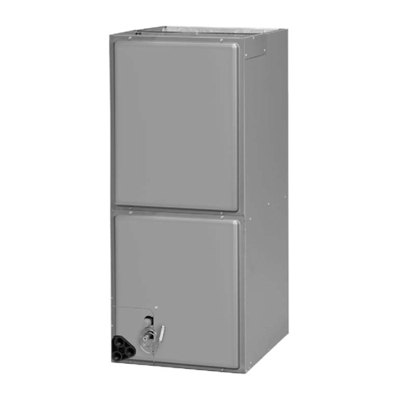
Page 9: Dimensions And Weights
2.5 DIMENSIONS & WEIGHTS FIGURE 3 NOTE: 24" CLEARANCE REQUIRED IN FRONT OF UNIT FOR FILTER DIMENSIONS AND WEIGHTS AND COIL MAINTENANCE. SUPPLY AIR ELECTRICAL CONNECTIONS MAY EXIT TOP OR EITHER SIDE HIGH VOLTAGE CONNECTION 7/8", 1 3/32", 1 31/32" DIA. KNOCK OUTS. FLANGES ARE PROVIDED FOR FIELD INSTALLATION LOW VOLTAGE CONNECTION... -
Page 10: Applications
3.0 APPLICATIONS 3.1 VERTICAL UPFLOW • Vertical Upflow is the factory configuration for all models (see Figure 3). • If a side return air opening is required, field fabricate a return air plenum with an open- ing large enough to supply unit and strong enough to support unit weight. •... -
Page 11: Horizontal
FIGURE 5 ROTATING CIRCUIT BREAKER - With screwdriver or pencil, pull white tab with hole away from breaker while setting that side of breaker into opening. When breaker is in place, release tab, locking circuit break- er into location in opening. - Repeat above operation for remaining breaker(s) (if more than one is provided). -
Page 12: Installation In An Unconditioned Space
FIGURE 6 VERTICAL DOWNFLOW & HORIZONTAL RIGHT APPLICATIONS DETAIL A ENSURE THE RETAIN- ING CHANNEL IS FULLY ENGAGED WITH THE COIL RAIL. RAILS RAILS FIGURE 7 INDOOR COIL AND DRAIN PAN SET-UP STRAPS REAR WATER CATCHER HORIZONTAL ADAPTER TOP AIR STOP FRONT WATER CATCHER VAPOR LINE... -
Page 13: Installation In Mobile/Manufactured Homes
due to the temperature of the conditioned air moving through the air handler and the air circulating around the unit where it is installed. For this reason, we recommend the fol- lowing for all air handler applications, but special attention should be paid to those installed in unconditioned spaces: •... -
Page 14: Electrical Wiring
4.0 ELECTRICAL WIRING Field wiring must comply with the National Electric Code (C.E.C. in Canada) and any applicable local ordinance. WARNING Disconnect all power to unit before installing or servicing. More than one disconnect switch may be required to de-energize the equipment. Hazardous voltage can cause severe personal injury or death. -
Page 15: Electrical Wiring
4.4 ELECTRICAL WIRING POWER WIRING • Field wiring must comply with the National Electrical Code (C.E.C. in Canada) and any applicable local ordinance. • Supply wiring must be 75°C minimum copper conductors only. • See electrical data for product Ampacity rating and Circuit Protector requirement. GROUNDING •... -
Page 16: Electric Heat Electrical Data
4.6 ELECTRICAL DATA – WITH ELECTRIC HEAT Installation of the UL Listed original equipment manufacturer provided heater kits listed in the following table is recommended for all auxiliary heating requirements. 4.6A ELECTRICAL DATA – WITH ELECTRIC HEAT: (-)HSL HEATER TYPE SUPPLY HEATER MINIMUM MAXIMUM... - Page 17 4.6A ELECTRICAL DATA – WITH ELECTRIC HEAT: (-)HSL - continued HEATER TYPE SUPPLY HEATER MINIMUM MAXIMUM AIR HANDLER CIRCUIT CIRCUIT MOTOR MODEL PH/HZ ELEMENTS CIRCUIT CIRCUIT MODEL (208/240V ) SINGLE CIRCUIT AMPS. AMPACITY - KW PER AMPACITY PROTECTION (480V) MULTIPLE CIRCUIT RXBH-1724?05J 3.6/4.8 1/60...
- Page 18 4.6A ELECTRICAL DATA – WITH ELECTRIC HEAT: (-)HSL - continued HEATER TYPE SUPPLY HEATER MINIMUM MAXIMUM AIR HANDLER CIRCUIT CIRCUIT MOTOR MODEL PH/HZ ELEMENTS CIRCUIT CIRCUIT MODEL (208/240V ) SINGLE CIRCUIT AMPS. AMPACITY - KW PER AMPACITY PROTECTION (480V) MULTIPLE CIRCUIT RXBH-1724A07C 5.4/7.2 3/60...
-
Page 19: B Electric Heat Electrical Data: (-)Hll
4.6B ELECTRICAL DATA – WITH ELECTRIC HEAT: (-)HLL Installation of the UL Listed original equipment manufacturer provided heater kits listed in the following table is recommended for all auxiliary heating requirements. HEATER TYPE SUPPLY HEATER MINIMUM MAXIMUM AIR HANDLER CIRCUIT CIRCUIT MOTOR MODEL... - Page 20 4.6B Electrical Data – With Electric Heat: (-)HLL - continued HEATER TYPE SUPPLY HEATER MINIMUM MAXIMUM AIR HANDLER CIRCUIT CIRCUIT MOTOR MODEL PH/HZ ELEMENTS CIRCUIT CIRCUIT MODEL (208/240V) SINGLE CIRCUIT AMPS. AMPACITY - KW PER AMPACITY PROTECTION (480V) MULTIPLE CIRCUIT RXBH-1724?07J 5.4/7.2 1/60...
- Page 21 4.6B Electrical Data – With Electric Heat: (-)HLL - continued HEATER TYPE SUPPLY HEATER MINIMUM MAXIMUM AIR HANDLER CIRCUIT CIRCUIT MOTOR MODEL PH/HZ ELEMENTS CIRCUIT CIRCUIT MODEL (208/240V) SINGLE CIRCUIT AMPS. AMPACITY - KW PER AMPACITY PROTECTION (480V) MULTIPLE CIRCUIT RXBH-1724?05J 3.6/4.8 1/60...
-
Page 22: C Heater Kit Supplemental Information
4.6C HEATER KIT SUPPLEMENTAL INFORMATION IR CONDITIONING DIVISION Contractor (-)HL -HM4821J should “mark M RK HE TER INST LLED/ or check” the L’ PP REIL DE CH UFF GE DE M RQUE INST LLE left column for the kit installed If a heater kit is listed both... - Page 23 NOTE: These low voltage application diagrams are generic. Your WIRE COLOR CODE: indoor/outdoor units may not have all the characteristics shown or may BK - BLACK G - GREEN PR - PURPLE Y - YELLOW not wire exactly as shown. Refer to the diagrams and information sent BR - BROWN GY - GRAY R - RED...
-
Page 24: Airflow Performance
5.0 AIRFLOW PERFORMANCE Airflow performance data is based on cooling performance with a coil and no filter in place. Select performance table for appropriate unit size, voltage and number of electric heaters to be used. Make sure external static applied to unit allows operation within the minimum and maximum limits shown in table below for both cooling and electric heat operation. -
Page 25: 240V Airflow Performance Data (-)Hsl
5.2 240V AIRFLOW PERFORMANCE DATA – (-)HSL (PSC MOTOR) PSC CFM[L/s] Air Delivery/RPM/Watts-240 Volts Motor Manufacturer Blower Size/ Model Speed Recommended Motor HP Motor External Static Pressure-Inches W.C. Number From Air Flow Range Speed Factory (Min / Max) CFM # of Speeds 0.1 [.02] 0.2 [.05] 0.3 [.07]... - Page 26 5.2 240V AIRFLOW PERFORMANCE DATA – (-)HSL (PSC MOTOR) - continued PSC CFM[L/s] Air Delivery/RPM/Watts-240 Volts Motor Manufacturer Blower Size/ Model Speed Recommended Motor HP Motor External Static Pressure-Inches W.C. Number From Air Flow Range Speed Factory (Min / Max) CFM # of Speeds 0.1 [.02] 0.2 [.05]...
-
Page 27: 115/208/480V Airflow Performance Data (-)Hsl
5.3 115/208/480V AIRFLOW PERFORMANCE DATA – (-)HSL (PSC MOTOR) PSC CFM[L/s] Air Delivery/RPM/Watts-240 Volts Motor Manufacturer Blower Size/ Model Speed Recommended Motor HP Motor External Static Pressure-Inches W.C. Number From Air Flow Range Speed Factory (Min / Max) CFM # of Speeds 0.1 [.02] 0.2 [.05] 0.3 [.07]... - Page 28 5.3 115/208/480V AIRFLOW PERFORMANCE DATA – (-)HSL (PSC MOTOR) - continued PSC CFM[L/s] Air Delivery/RPM/Watts-240 Volts Motor Manufacturer Blower Size/ Speed Recommended Motor H.P. Motor Model External Static Pressure-Inches W.C. Number From Air Flow Range Speed Factory (Min / Max) CFM # of Speeds 0.1 [.02] 0.2 [.05]...
-
Page 29: 115/208/240V Airflow Performance Data (-)Hll
5.4 115/208/240/480V AIRFLOW PERFORMANCE DATA – (-)HLL (X-13 MOTOR) X-13 Motor Manufacturer CFM[L/s] Air Delivery/RPM/Watts-115/208/240 Volts Blower Size/ Model Tonnage Speed Recommended Motor Motor H.P. External Static Pressure-Inches W.C. Number Application From Air Flow Range Speed # of Speeds Factory (Min / Max) CFM 0.10 [.02] 0.20 [.05] 0.30 [.07] 0.40 [.10] 0.50 [.12] 0.60 [.15] 0.70 [.17] 689 [325]... - Page 30 5.4 115/208/240/480V AIRFLOW PERFORMANCE DATA – (-)HLL (X-13 MOTOR) - continued X-13 Motor Manufacturer CFM[L/s] Air Delivery/RPM/Watts-115/208/240 Volts Blower Size/ Model Tonnage Speed Recommended Motor Motor H.P. External Static Pressure-Inches W.C. Number Application From Air Flow Range Speed # of Speeds Factory (Min / Max) CFM 0.10 [.02] 0.20 [.05] 0.30 [.07] 0.40 [.10] 0.50 [.12] 0.60 [.15] 0.70 [.17]...
- Page 31 5.4 115/208/240/480V AIRFLOW PERFORMANCE DATA – (-)HLL (X-13 MOTOR) - continued X-13 Motor Manufacturer CFM[L/s] Air Delivery/RPM/Watts-115/208/240 Volts Blower Size/ Model Tonnage Speed Recommended Motor Motor H.P. External Static Pressure-Inches W.C. Number Application From Air Flow Range Speed # of Speeds Factory (Min / Max) CFM 0.10 [.02] 0.20 [.05] 0.30 [.07] 0.40 [.10] 0.50 [.12] 0.60 [.15] 0.70 [.17]...
-
Page 32: Ductwork
6.0 DUCTWORK Field ductwork must comply with the National Fire Protection Association NFPA 90A, NFPA 90B and any applicable local ordinance. WARNING Do not, under any circumstances, connect return ductwork to any other heat producing device such as fireplace insert, stove, etc. Unauthorized use of such devices may result in fire, carbon monoxide poisoning, explo- sion, personal injury or property damage. -
Page 33: Duct Flanges
FIGURE 15 CONDENSATE DRAIN TRAP DO NOT OPERATE UNIT WITHOUT CONDENSATE DRAIN TRAP. UNIT DO NOT OVERTIGHTEN DRAIN FITTING UNIT MUST BE SLIGHTLY INCLINED TOWARD DRAIN CONNECTION. IMPORTANT: When making drain fitting connections to drain pan, do not overtighten. Overtightening fittings can split pipe connections on the drain pan. •... -
Page 34: Sequence Of Operation
IMPORTANT: DO NOT DOUBLE FILTER THE RETURN AIR DUCT SYSTEM. DO NOT FILTER THE SUPPLY AIR DUCT SYSTEM. WARNING Do not operate the system without filters. A portion of the dust entrained in the air may temporarily lodge in the duct runs and at the supply registers. Any cir- culated dust particles could be heated and charred by contact with the air han- dler elements. -
Page 35: Emergency Heat (Heating Heat Pump)
9.6 EMERGENCY HEAT (HEATING HEAT PUMP) • If selector switch on thermostat is set to the emergency heat position, the heat pump will be locked out of the heating circuit, and all heating will be electric heat. Jumper should be placed between W and E on the thermostat sub-base so that the electric heat control will transfer to the first stage heat on the thermostat. -
Page 36: Pre-Start Checklist
11.0 PRE-START CHECKLIST PRE-START CHECKLIST Is unit properly located, level, secure and service- able? Has auxiliary pan been provided under the unit with separate drain? (Units installed above a finished ceiling). Is condensate line properly sized, run, trapped, pitched and tested? Is ductwork correctly sized, run, taped and insulat- Have all cabinet openings and wiring been sealed with caulking? -
Page 37: Indoor Coil/Drain Pan/Drain Line
12.2 INDOOR COIL - DRAIN PAN - DRAIN LINE Inspect the indoor coil once each year for cleanliness and clean as necessary. In some cases, it may be necessary to remove the filter and check the return side of the coil with a mirror and flashlight. -
Page 38: Motor Replacement
12.6 MOTOR REPLACEMENT With the blower assembly removed, the indoor blower motor can be removed and replaced using the following procedure: • Remove motor leads from the motor capacitor and blower relay. Note lead locations for ease of reassembly. Pull leads from plastic bushing in blower side. •... -
Page 39: Accessories-Kits-Parts
When ordering replacement parts, it is necessary to order by part number and include with the order the complete model number and serial number from the unit data plate. (See parts list for unit component part numbers). 14.0 ACCESSORIES-KITS-PARTS • Combustible Floor Base RXHB- for downflow applications. Combustible Floor Model Cabinet Size Base Model Number... - Page 40 FIGURE 17 EXTERNAL FILTER RACK: RXHF- B17, B21, B24 1.50 • Horizontal Adapter Kit RXHH- This horizontal adapter kit is used to convert Upflow/Downflow only models to hori- zontal flow. See the following table to order proper horizontal adapter kit. Horizontal Adapter Kit Horizontal Adapter Kit Coil Model...