
Related Manuals for Icom IC-F3032T


Summary of Contents for Icom IC-F3032T
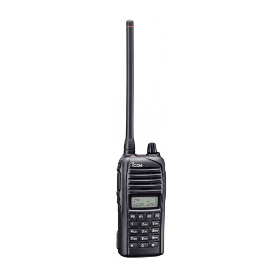
- Page 1 INSTRUCTION MANUAL VHF TRANSCEIVERS iF3032T iF3032S UHF TRANSCEIVERS iF4032T iF4032S The photo shows the VHF transceiver (S type)
-
Page 2: About Ce
Icom, Icom Inc. and Icom logo are registered trademarks of Icom Incorporated life. Do not dispose of these products as unsorted municipal (Japan) in Japan, the United States, the United Kingdom, Germany, France, waste. -
Page 3: Explicit Definitions
Icom transceivers or Icom chargers. Only broken, or the transceiver has been dropped. Icom battery packs are tested and approved for use with Icom transceivers or charged with Icom chargers. Using third-party or counterfeit battery packs or chargers may cause smoke, fire, or cause the battery to burst. - Page 4 The transceiver will become hot when operating it continuously for long periods of time. disturbances, riots, war, or radioactive contamination. • The use of Icom transceivers with any equipment that is not manufactured or approved by Icom.
-
Page 5: Table Of Contents
TABLE OF CONTENTS IMPORTANT ................i ■ Scrambler function .............13 ■ MDC 1200 system operation ........14 ABOUT CE ................i DISPOSAL ................i 4 BATTERY CHARGING ..........15–19 EXPLICIT DEFINITIONS ............i ■ Caution ...............15 RECOMMENDATION ............ii ■ Optional battery chargers ...........17 PRECAUTIONS .............. -
Page 6: Accessories
ACCESSORIES ■ Supplied accessories D Battery pack To attach the battery pack: Slide the battery pack in the direction of the arrow (q) until NOTE: Some accessories are not supplied with depending the battery release button makes a ‘click’ sound. on the transceiver version. -
Page 7: Accessories
ACCESSORIES D Belt clip D Jack cover To attach the belt clip: To attach the jack cover: q Release the battery pack if it is attached. q Attach the jack cover to the [MIC/SP] jack. w Slide the belt clip in the direction of the arrow until the belt w Tighten the screws. -
Page 8: Panel Description
PANEL DESCRIPTION ■ Front panel y10-KEYPAD (Depending on version) T he keypad allows you to enter digits to: • Select memory channels and tone channels • Select DTMF codes (during transmit) • Set TX codes • Start up with the password u DEALER-ASSIGNABLE KEYS [P0] to [P3] D esired functions can be assigned independently by your Speaker... -
Page 9: Function Display
PANEL DESCRIPTION ■ Function display y SCRAMBLER INDICATOR Displayed when the voice scrambler function is activated. u BELL INDICATOR D isplayed or blinks when the specific 2-Tone code is re- ceived, according to the presetting. i KEY LOCK INDICATOR D isplayed during the key lock function is ON. o BATTERY INDICATOR D isplayed or blinks when the battery power decreases to a q TRANSMIT INDICATOR... -
Page 10: Assignable Function Keys
When the power ON scan function is turned OFF: Consult your Icom dealer or system operator for details con- cerning your transceivers setting. Push to start and cancel scanning operation. In case of transmission during scan, scanning will be cancelled. - Page 11 PANEL DESCRIPTION SCAN ADD/DEL (TAG) KEY MR-CH 1/2/3/4 KEYS ➥ Push to add a channel to, or delete it from the current scan Push to select memory channels 1 to 4 in the operating zone list. directly. • When a channel is added to the current scan list, the display MONI KEY shows “SCAN ON.”...
-
Page 12: Panel Description
PANEL DESCRIPTION TALK AROUND KEY EMERGENCY KEY Push to turn the talk around function ON and OFF. Hold down to transmit the emergency call. • The talk around function equalizes the transmit frequency to the • The transceiver can transmit the emergency call silently or audibly receive frequency for transceiver-to-transceiver communication. -
Page 13: Basic Operation
BASIC OPERATION ■ Turning power ON D Battery type selection Prior to using the transceiver for the first time, the battery The battery type must be selected according to the attaching pack must be fully charged for optimum life and operation. battery type when turning ON the transceiver. -
Page 14: Channel Selection
BASIC OPERATION ■ Channel selection ■ Call procedure Several types of channel selections are available. Methods When your system employs tone signaling (excluding CTCSS may differ according to your system set up. and DTCS), the call procedure may be necessary prior to voice transmission. -
Page 15: Receiving And Transmitting
BASIC OPERATION ■ Receiving and transmitting D Transmitting notes CAUTION: Transmitting without an antenna may damage the transceiver. See page 1 for accessory attachments. • Transmit inhibit function The transceiver has several inhibit functions which restrict Receiving: transmission under the following conditions: q Rotate [VOL] to turn the power ON. -
Page 16: D Tx Code Channel Selection
BASIC OPERATION D TX code channel selection D DTMF transmission If the transceiver has [TX Code CH Select] assigned to it, If the transceiver has [DTMF Autodial] assigned to it, the the indication can be toggled between the operating channel automatic DTMF transmission function is available. -
Page 17: User Set Mode
BASIC OPERATION ■ User set mode Emergency Call When [Emergency] is held down for the specified time peri- The User Set mode enables you to set the seldom changed od*, the emergency signal is transmitted once, or repeatedly, settings, and customize the transceiver operation to suit your on the specified emergency channel. -
Page 18: Priority A Channel Selection
BASIC OPERATION ■ Priority A channel selection ■ Stun function Depending on the presetting, the Priority A channel is se- When the specified ID, set as a stun ID or kill ID, is received, lected each time the transceiver power is turned ON. the stun function is activated. -
Page 19: Mdc 1200 System Operation
BASIC OPERATION ■ MDC 1200 system operation D Receiving an Emergency Call The MDC 1200 signaling system enhances your transceiv- er’s capabilities. It allows PTT ID*, Emergency signaling, and q When an emergency call is received; receiving Radio Check. Also, the dispatcher can stun and re- •... -
Page 20: Battery Charging
Excessive temperatures may also degrade battery pack’s abnormal odor, heats up, or is discolored or deformed. If any performance or shorten the battery cell’s life. of these conditions occur, contact your Icom dealer or dis- R DANGER! NEVER expose the battery pack to rain, snow, tributor. -
Page 21: D Charging Caution
BC-160 and BC-171 (0˚C to +45˚C). • Approximately five years have passed since the battery was BC-119N and BC121N (+10˚C to +40˚C). Icom recommends manufactured. charging the battery at +20˚C. The battery may heat up or rup- •... -
Page 22: Optional Battery Chargers
BATTERY CHARGING ■ Optional battery chargers D Rapid charging with the BC-160 D Regular charging with the BC-171 The optional BC-160 provides rapid charging of the Li-ion The optional BC-171 provides regular charging of the Li-ion battery pack. battery pack. •... - Page 23 BATTERY CHARGING D AD-106 installation D Rapid charging with the BC-119N+AD-106 The AD-106 must be installed into the BC- The optional BC-119N provides rapid charging of the Li-ion charger adapter 119N or BC-121N before battery charging. battery pack. The following items are additionally required. •...
- Page 24 BATTERY CHARGING D Rapid charging with the BC-121N+AD-106 The optional BC-121N allows up to 6 Li-ion battery packs to IMPORTANT: Battery charging caution be charged simultaneously. The following items are addition- Ensure the guide tabs on the battery pack are correctly ally required.
-
Page 25: Optional Swivel Belt Clip
OPTIONAL SWIVEL BELT CLIP ■ MB-93 contents r Clip the belt clip to a part of your belt. And insert the trans- ceiver into the belt clip until the base clip inserted fully into the groove. Qty. q Belt clip ................1 w Base clip .................1 ■... -
Page 26: Detaching
OPTIONAL SWIVEL BELT CLIP ■ Detaching q Turn the transceiver upside down in the direction of the w Release the battery pack if it is attached. (p. 2) e Pinch the clip (q), and slide the base clip in the direction arrow and pull out from the belt clip. -
Page 27: Speaker Microphone
SPEAKER MICROPHONE ■ Optional HM-168LWP description ■ Attachment Attach the connector of the speaker-microphone into the [SP Alligator type clip MIC] jack on the transceiver and tighten the screws with fin- To attach the speaker-mic. gers. to your shirt or collar, etc. NOTE: Use only your fingers instead of tools to tighten the screws. -
Page 28: Options
OPTIONS D BATTERY PACK • BC-160 + BC-145S desktop charger ac adapter For rapid charging of battery packs. A power adapter is sup- Battery pack Voltage Capacity Battery life* plied with the charger depending on versions. 2200 mAh (minimum) Charging time: Approximately 3.5 hours for the BP-232WP BP-232WP 7.4 V 17.5 hrs. - Page 29 OPTIONS D OPTIONAL UNITS Some options may not be available in some countries. Ask • UT-96R tone unit your dealer for details. • UT-108R dtmf decoder unit Provides pager and code squelch capabilities. • UT-109R /UT-110R* voice scrambler units Non-rolling type (UT-109R)/Rolling type (UT-110R)* voice scrambler unit provides higher communication security.
-
Page 30: Country Code List
COUNTRY CODE LIST ISO 3166-1 Country Codes Country Codes Austria Liechtenstein Belgium Lithuania Bulgaria Luxembourg Croatia Malta Czech Republic Netherlands Cyprus Norway Denmark Poland Estonia Portugal Finland Romania France Slovakia Germany Slovenia Greece Spain Hungary Sweden Iceland Switzerland Ireland Turkey Italy United Kingdom Latvia... - Page 31 MEMO...
- Page 32 < Intended Country of Use > A-6999D-1EU-e Printed in Japan © 2012–2017 Icom Inc. 1-1-32 Kamiminami, Hirano-ku, Osaka 547-0003, Japan Printed on recycled paper with soy ink.