Table of Contents
Advertisement
MINI COMPONENT SYSTEM
RX-E400/
The CRX-E400 is composed of the RX-E400 and the CDX-E400.
This service manual is for the RX-E400 (including NX-E400).
For the CDX-E400 service manual, please refer to the following publication numbers :
This manual has been provided for the use of authorized YAMAHA Retailers and their service personnel.
It has been assumed that basic service procedures inherent to the industry, and more specifically YAMAHA Products, are already
known and understood by the users, and have therefore not been restated.
WARNING:
IMPORTANT:
The data provided is believed to be accurate and applicable to the unit(s) indicated on the cover. The research, engineering, and service
departments of YAMAHA are continually striving to improve YAMAHA products. Modifications are, therefore, inevitable and
specifications are subject to change without notice or obligation to retrofit. Should any discrepancy appear to exist, please contact the
distributor's Service Division.
WARNING:
IMPORTANT:
CONTENTS
TO SERVICE PERSONNEL . . . . . . . . . . . . . . . . . . . . 2
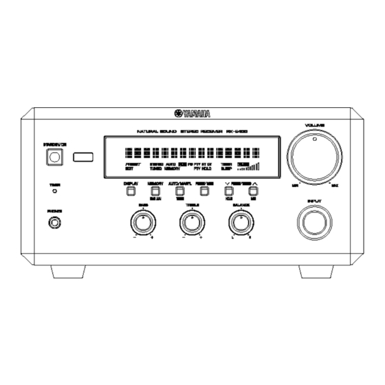
FRONT PANELS . . . . . . . . . . . . . . . . . . . . . . . . . . . 2-3
REAR PANELS . . . . . . . . . . . . . . . . . . . . . . . . . . . . . . 3
SPECIFICATIONS . . . . . . . . . . . . . . . . . . . . . . . . . . 4-5
INTERNAL VIEW . . . . . . . . . . . . . . . . . . . . . . . . . . . . . 5
DISASSEMBLY PROCEDURES . . . . . . . . . . . . . . . 6-7
TEST MODE . . . . . . . . . . . . . . . . . . . . . . . . . . . . . . . 8-9
AMP ADJUSTMENTS . . . . . . . . . . . . . . . . . . . . . . . . . 9
IC DATA . . . . . . . . . . . . . . . . . . . . . . . . . . . . . . . . 10-12
BLOCK DIAGRAM . . . . . . . . . . . . . . . . . . . . . . . . . . . 13
1 0 0 8 0 9
CDX-E400
IMPORTANT NOTICE
Failure to follow appropriate service and safety procedures when servicing this product may result in personal
injury, destruction of expensive components, and failure of the product to perform as specified. For these reasons,
we advise all YAMAHA product owners that any service required should be performed by an authorized YAMAHA
Retailer or the appointed service representative.
The presentation or sale of this manual to any individual or firm does not constitute authorization, certification or
recognition of any applicable technical capabilities, or establish a principle-agent relationship of any form.
Static discharges can destroy expensive components. Discharge any static electricity your body may have
accumulated by grounding yourself to the ground buss in the unit (heavy gauge black wires connect to this buss).
Turn the unit OFF during disassembly and part replacement. Recheck all work before you apply power to the unit.
PRINTED CIRCUIT BOARD . . . . . . . . . . . . . . . . 14-17
PIN CONNECTION DIAGRAM . . . . . . . . . . . . . . . . . 18
SCHEMATIC DIAGRAM . . . . . . . . . . . . . . . . . . . 19-20
DISPLAY DATA . . . . . . . . . . . . . . . . . . . . . . . . . . . . . 20
PARTS LIST . . . . . . . . . . . . . . . . . . . . . . . . . . . . . 21-28
REMOTE CONTROL TRANSMITTER . . . . . . . . . . . . 29
SYSTEM CONTROL . . . . . . . . . . . . . . . . . . . . . . 30-38
NX-E400 . . . . . . . . . . . . . . . . . . . . . . . . . . . . . . . . . . . 39
PARTS LIST FOR CARBON RESISTORS . . . . . . . . 40
CRX-E400
NX-E400
SERVICE MANUAL
SERVICE MANUAL
100808
Advertisement
Table of Contents

Related Manuals for Yamaha CRX-E400


Summary of Contents for Yamaha CRX-E400
-
Page 1: Table Of Contents
This manual has been provided for the use of authorized YAMAHA Retailers and their service personnel. It has been assumed that basic service procedures inherent to the industry, and more specifically YAMAHA Products, are already known and understood by the users, and have therefore not been restated. -
Page 2: To Service Personnel
RX-E400 TO SERVICE PERSONNEL AC LEAKAGE 1. Critical Components Information EQUIPMENT WALL TESTER OR Components having special characteristics are marked Z OUTLET UNDER TEST EQUIVALENT and must be replaced with parts having specifications equal to those originally installed. 2. Leakage Current Measurement (For 120V Models Only) When service has been completed, it is imperative to verify that all exposed conductive surfaces are properly insulated INSULATING... -
Page 3: Rear Panels
RX-E400 B, G models REAR PANELS U, C models B model R model G model A model... -
Page 4: Specifications
TREBLE : Boost/cut ....±10dB (20kHz) Accessories of CRX-E400 ... AM loop antenna x 1 Turnover Frequency . -
Page 5: Internal View
RX-E400 SPEAKER SECTION (NX-E400) DIMENSIONS (RX-E400) Type ... . 2way Bass-reflex Magnetic Shielding Type Driver Woofer ..... . 13cm (5-1/8") Cone Type Tweeter . -
Page 6: Disassembly Procedures
RX-E400 DISASSEMBLY PROCEDURES (Remove parts in disassembly order as numbered.) 1. Removal of Top Cover a. Remove 4 screws ( q ) and 4 screws ( w ) in Fig. 1. b. Lift the Top Cover at the rear and move it rear-ward slantingly. 2. - Page 7 RX-E400 Servicing Position a. Remove the Top Cover and the Front Panel Unit. b. Remove 6 screws ( y ) in Fig. 3. c. Remove 5 screws ( u ) in Fig. 3. d. Remove 3 screws ( i ) in Fig. 3. e.
-
Page 8: Test Mode
RX-E400 TEST MODE POWER Off condition STANDBY/ON Key is pushed while pushing DISPLAY Key and AUTO/MAN'L Key. TEST MODE indication. When present mode is TEST MODE DOWN TEST MODE UP carried out. PRESET/TUNING B Key PRESET/TUNING N Key PRESET/BAND Key Test mode number Test mode number Execute test mode. -
Page 9: Amp Adjustments
RX-E400 FACTORY PRESET PRESET No. BAND MARKETS U, C, R (100k/10k) 98.1 95.1 87.5 101.5 107.9 88.1 106.1 107.9 FM (MHz) A, B, G, R, (50k/9k) 98.10 95.10 87.50 101.50 108.00 88.10 106.10 107.90 U, C, R (100k/10k) 1080 1400 1710 1350 1440... -
Page 10: Ic Data
RX-E400 IC DATA IC700 : M30217M8-A103FP (16 bit µ-COM) P67/FLD7 P24/FLD36 P66/FLD6 P25/FLD37 P65/FLD5 P26/FLD38 P64/FLD4 P27/FLD39 P63/FLD3 P30/FLD40 P62/FLD2 P31/FLD41 P61/FLD1 P32/FLD42 P60/FLD0 P33/FLD43 P34/FLD44 P107/AN7 P35/FLD45 P106/AN6 P36/FLD46 P105/AN5 P37/FLD47 P104/AN4 P40/FLD48 P103/AN3 P41/FLD49 P102/AN2 P42/FLD50 P101/AN1 P43/FLD51 AVSS P44/TXD0/FLD52 P100/AN0... - Page 11 RX-E400 IC700 : M30217M8-A103FP (16 bit µ-COM) PORT Name IN/OUT Function C2B(LC72722/LC78211)CE OUT [1:DATA transmission] S-CLK LC72722/LC78211 CLK OUT (Serial I/O-1) DAT I S-IN LC72722 DATA IN (Serial I/O-1) DAT O S-OUT LC72722/LC78211 DATA OUT (Serial I/O-1) Mut A AMP MUTE OUT [0:MUTE ON] Mut T Tuner MUTE OUT (TUNER)
- Page 12 RX-E400 IC700 : M30217M8-A103FP (16 bit µ-COM) PORT Name IN/OUT Function SEG 25 SEGMENT 25 (P25) (VEE internal pull-down) SEG 26 SEGMENT 26 (P26) (VEE internal pull-down) SEG 27 SEGMENT 27 (P27) (VEE internal pull-down) SEG 28 SEGMENT 28 (P28) (VEE internal pull-down) SEG 29 SEGMENT 29 (P29)
-
Page 13: Block Diagram
RX-E400 BLOCK DIAGRAM • MAIN: See page19 → SCHEMATIC DIAGRM • OPERATION: See page 20 → SCHEMATIC DIAGRM RDS (B,G only) –VP 4.332MHz MAIN. P. C. B. CB103 R745 2 58 59 TERMINAL No. REST DAT O TO: µ-COM Q108 AM/FM TUNER IC109 FLUORESCENT DISPLAY... -
Page 14: Printed Circuit Board
RX-E400 PRINTED CIRCUIT BOARD (Foil side) Semiconductor Location OPERATION P. C. B. (Lead Type Device View) Ref. No. Location Ref. No. Location Ref. No. Location Q700 D701 IC700 Q701 D702 Q702 D703 Q703 D705 MAIN (1) D706 W705 D707 D708 D709 D710 D711... - Page 15 RX-E400 Semiconductor Location PRINTED CIRCUIT BOARD (Foil side) Ref. No. Location Ref. No. Location Ref. No. Location Q250 Q269A CIRCUIT CHANGES BY MARKET. D251 Q251 Q269C D252 U, C B, G Q252 Q271 D253 D254 Q253 Q272 C310, 311 D255 Q254 Q273 C305, 306...
- Page 16 RX-E400 PRINTED CIRCUIT BOARD (Foil side) MAIN ( 2 ) P. C. B. MAIN ( 3 ) P. C. B. MAIN ( 4 ) P. C. B. MAIN (2) TAPE HP-L HP-R W253 MAIN (1) TINR VOL-DN TFBR VOL-UP SGND TFBL TINL DAT I...
- Page 17 RX-E400 PRINTED CIRCUIT BOARD (Foil side) CIRCUIT CHANGES BY MARKET. R model MAIN ( 6 ) P. C. B. U, C MAIN ( 5 ) P. C. B. MAIN ( 8 ) P. C. B. F231 F401 CB233, 234 J250 W232 MAIN (6) R234...
-
Page 18: Pin Connection Diagram
RX-E400 PIN CONNECTION DIAGRAM Diodes Transistors 1SS133 NJM78L05A-T3 NJM2068D-D LB1641 2SA1740S (R, S) 2SA1708 (S, T) 1SS270A 2SA1317 (R, S, T) 2SC4488 (S, T) 1SR139-400 2SC3330 (S, T) 2SC4481 (S, T) HZS5B2TD DTA114ES HZS5C2TD Anode HZS12A2TD HZS12B2TD 1:INPUT HZS202TD 2:COMMON HZS302TD 3:OUTPUT Cathode... - Page 19 RX-E400 Each voltage represents the voltage when receiving FM (stereo) signal and the voltage in the parentheses ( ) is the voltage when receiving AM signal. SCHEMATIC DIAGRAM (MAIN) CIRCUIT CHANGES BY MARKET. O : USED X : NOT USED 14.2 14.2 35.6...
-
Page 20: Schematic Diagram
RX-E400 SCHEMATIC DIAGRAM (OPERATION) DISPLAY DATA -24.1 -29.1 V700 : 16-BT-67GN (V3579300) PATTERN AREA -28.8 -26.7 -26.6 -26.7 -26.6 -26.7 PIN CONNECTION -26.6 -26.7 -26.7 -24.5 -24.5 -26.7 -26.7 -26.7 -28.8 -26.7 -26.7 -29.1 -26.7 REGULATOR -26.7 -26.7 11.9 -26.7 P-19 [F-3] -26.7 -26.7... -
Page 21: Parts List
RX-E400 P ARTS LIST WARNING Components having special characteristics are marked and must be replaced with parts having specifications equal to those originally installed. ELECTRICAL PARTS Carbon resistors (1/6W or 1/4W) are not included in the ELECTRICAL PARTS List. For the part Nos. of the carbon resistors, refer to the last page. ABBREVIATIONS IN THIS LIST ARE AS FOLLOWS : C.A.EL.CHP : CHIP ALUMI. - Page 22 RX-E400 P.C.B. OPERATION Schm Schm Ref. PART NO. Description Market Ref. PART NO. Description Market V9333900 P.C.B. SI:OPERATION SW706 V2014900 SW.TACT EVQ21304M CB701 VP682200 CN.BS.PIN 8P SW707 V2014900 SW.TACT EVQ21304M U700 V3872300 L.DTCT PIC-28143TH5 CB705 Vi878300 CN.BS.PIN 5P CB706 Vi878900 CN.BS.PIN 11P V700 V3579300 FL.DSPLY 16-BT-67GN...
- Page 23 RX-E400 P.C.B. MAIN Schm Schm Ref. PART NO. Description Market Ref. PART NO. Description Market V9319100 P.C.B. MAIN C162 VA761100 C.CE 27pF V9332500 P.C.B. MAIN C163 VA761100 C.CE 27pF C165 VG287500 C.EL 47uF V9332000 P.C.B. MAIN V9332100 P.C.B. MAIN C166 VG287500 C.EL 47uF V9332200 P.C.B.
- Page 24 RX-E400 P.C.B. MAIN Schm Schm Ref. PART NO. Description Market Ref. PART NO. Description Market C289 VG291200 C.EL 47uF IC109 XY534A00 IC LC72722 C290 VR325000 C.MYLAR 100pF 100V IC113 XJ757A00 IC NJM78L05A-T3 C291 UA654680 C.MYLAR 0.068uF IC210 XA987A00 IC NJM2068D-D C292 UA654680 C.MYLAR 0.068uF...
- Page 25 RX-E400 P.C.B. MAIN Schm Schm Ref. PART NO. Description Market Ref. PART NO. Description Market Q541 VR510800 TR 2SD2396 J,K TE231 VU543300 OUTLET.AC 1P R167 HV753220 R.CAR.FP 2.2Ω 1/4W TE231 VU543400 OUTLET.AC 2P R168 HV753220 R.CAR.FP 2.2Ω 1/4W TE250 VY696300 TERM.SP R169 HV753470 R.CAR.FP 4.7Ω...
- Page 26 RX-E400 EXPLODED VIEW R model B model A model 2-112 2-1 (6) 2-110 R,G,B models only 2-106 2-105 2-111 2-110 1-111 1-110 1-103 1-10 1-102 1-107 1-104 1-106 1-110 1-103 1-105 1-101 200-1 % : Note on the Operation PCB Of the Operation PCB(1-1) part Nos., only the silver (SI) type part Nos.
- Page 27 RX-E400 MECHANICAL PARTS Ref. PART NO. Description Remarks Markets * 1-1 V9333900 P.C.B. ASS'Y SI:OPERATION 1-10 MF117120 FLEXIBLE FLAT CABLE 17P 120mm * 1-101 V8783300 FRONT PANEL RXE400SI * 1-101 V8783500 FRONT PANEL-RDS RXE400RDSSI * 1-101 V8783400 FRONT PANEL RXE400GD 1-101 V8783600 FRONT PANEL-RDS RXE400RDSGD * 1-102 V8785000 SUB PANEL-RX...
- Page 28 RX-E400 Ref. PART NO. Description Remarks Markets * 113 V8786100 KNOB/D10-P * 113 V8786200 KNOB/D10-P VQ368600 PUSH RIVET P3555-B VR264400 SPACER * 122 V9817200 SHEET/BARRIER-RX VN413300 BIND HEAD BONDING B-T. SCREW 3x8 MFZN2BL VY731200 BONDING HEAD TAPPING SCREW 3x10 MFNI33 EP600830 BIND HEAD B-TITE SCREW MFC2BL EP600250 BIND HEAD B-TITE SCREW...
-
Page 29: Remote Control Transmitter
RX-E400 REMOTE CONTROL TRANSMITTER SCHEMATIC DIAGRAM KI/O6 KI/O5 KI/O7 KI/O4 KI/O3 KI/O2 KI/O1 2SD1781KR 220Ω DC3V B1 KI/O0 X OUT X IN 455kHz 47µF/16 RESET 0.1µF U, C, R, A models B, G models TRANSMISSION FORMAT: NEC-FORMAT CUSTOM CODE (HEX): 78 Data Code Data Code Name... -
Page 30: System Control
RX-E400 SYSTEM CONTROL Features • One bus line controls all the units. • Units are connected in series, using monaural mini jacks. • Units can be connected in any order Description of Operation Bus line RX CPU CDX CPU M DX CPU K X CPU Serial Data Format 12mS... - Page 31 RX-E400 Description of main system operation 1) POWER ON/OFF processing [(1) to (4)] M DX U, C, R, G models • The power cord of each unit is connected to the AC outlet in series and switched on and off through the RX relay.
- Page 32 RX-E400 ( 1 ) POWER ON PROCESSING ( Receiver ) When the power is turned on at the receiver, the relay of the AC outlet is turned on to supply power to each unit. Each unit informs the receiver of its status when started (secondary connection status). Remarks The indicator of each POWER SW ON...
- Page 33 RX-E400 (4)POWER OFF processing (except receiver) When the power is turned off at a unit other than the receiver, the unit informs the receiver of the status when the power off processing has been completed. Remarks POWER OFF The receiver detects the units being After POWER OFF processing connected when...
- Page 34 RX-E400 (7)TIMER PLAY Timer play by built-in timer Remarks Timer time reached This function is Execution of ignored when no PLAY unit is (1) Power ON processing connected. (Receiver) Function selection [FUNC_CD] [FUNC_MD] [FUNC_TAPE] [FUNC_TU] [FUNC_AUX] Timer play command transmitted when PLAY unit is CD, MD or TAPE [CD_TPLAY]...
- Page 35 RX-E400 (9)AUTO POWER OFF The receiver turns off the power when the unit is left at stop for half an hour without any operation. Remarks When the unit is left at stop without any key operation Auto power off request [APOFF_REQ] When a CD request is made for the first...
- Page 36 RX-E400 (10)AUTO POWER ON Function to turn ON the power without using the power switch on the unit other than the receiver Remarks Auto power ON applicable key Auto power ON applicable key Auto power ON applicable key input input input When in the power OFF state When in the power OFF state...
- Page 37 RX-E400 Function CODE CODE CODE CODE CD_STOP Remote control CD_PLAY/PAUSE CD_EJECT CD_SKIP+ CD_SKIP- SEARCH+ SEARCH- SEACH_END CD_RANDAM CD_TIME CD_PRG CD_RPT TAPE PEAK SEARCH CD_0 CD_1 CD_2 CD_3 CD_4 CD_5 CD_6 CD_7 CD_8 CD_9 CD_10 MD_STOP MD_PLAY/PAUSE MD_EJECT MD_SKIP+ MD_SKIP- SEARCH+ SEARCH- SEACH_END MD_RANDAM...
- Page 38 RX-E400 Reception status of operation switches during recording (*=AUX or TUNER) EDIT RECORDING SYNCHRONOUS or MANUAL RECORDING Unit C^T,M *^T,M POWER FUNCTION POWER EJECT PLAY STOP SKIP SEARCH POWER EJECT PLAY STOP SKIP SEARCH TAPE POWER EJECT PLAY STOP FF/REW Principle of switch rec operation reception •...
-
Page 39: Nx-E400
RX-E400 NX-E400 30 x 2 1-12 TWEETER (XW275A00) 2.7 /5W 3.3 F/63V WOOFER INPUT (XW276A00) 1.0mH Ref. PART NO. Description Remarks Markets V9509300 CABINET ASS'Y 1-12 CB605250 HOLDER V9509700 FRONT GRILLE ASS'Y XW275A00 DRIVER TWEETER 2.5cm 5Ω 40W XW276A00 DRIVER WOOFER 13cm 6Ω... -
Page 40: Parts List For Carbon Resistors
RX-E400 Parts List for Carbon Resistors Value 1/4W Type Part No. 1/6W Type Part No. Value 1/4W Type Part No. 1/6W Type Part No. 1.0 Ω 3100 3100 7100 10 kΩ 7100 HJ35 HF85 HF45 HF45 1.8 Ω 3180 7110 11 kΩ...