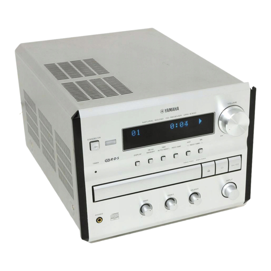
Yamaha CRX-E300 Service Manual
Mini component system
Hide thumbs
Also See for CRX-E300:
- Owner's manual (192 pages) ,
- Service manual (87 pages) ,
- Instructions for use manual (28 pages)
Table of Contents
Advertisement
Quick Links
CRX-E300/
This manual has been provided for the use of authorized YAMAHA Retailers and their service personnel.
It has been assumed that basic service procedures inherent to the industry, and more specifically YAMAHA Products, are already
known and understood by the users, and have therefore not been restated.
WARNING:
IMPORTANT:
The data provided is believed to be accurate and applicable to the unit(s) indicated on the cover. The research, engineering, and
service departments of YAMAHA are continually striving to improve YAMAHA products. Modifications are, therefore, inevitable
and specifications are subject to change without notice or obligation to retrofit. Should any discrepancy appear to exist, please
contact the distributor's Service Division.
WARNING:
IMPORTANT:
I CONTENTS
TO SERVICE PERSONNEL .......................................... 2
FRONT PANELS ............................................................ 4
REAR PANELS .......................................................... 5~6
SPECIFICATIONS ...................................................... 6~7
INTERNAL VIEW ........................................................... 7
DISASSEMBLY PROCEDURES / 分解手順 ........... 8~10
CDメカユニット動作チェック ..................................... 11
TEST MODE / テストモード .................................. 12~15
CD TEST MODE / CDテストモード ...................... 16~17
CD基本動作チャート .............................................. 18~21
1 0 0 8 0 5
MINI COMPONENT SYSTEM
SERVICE MANUAL
IMPORTANT NOTICE
Failure to follow appropriate service and safety procedures when servicing this product may result in personal
injury, destruction of expensive components, and failure of the product to perform as specified. For these reasons,
we advise all YAMAHA product owners that any service required should be performed by an authorized
YAMAHA Retailer or the appointed service representative.
The presentation or sale of this manual to any individual or firm does not constitute authorization, certification or
recognition of any applicable technical capabilities, or establish a principle-agent relationship of any form.
Static discharges can destroy expensive components. Discharge any static electricity your body may have
accumulated by grounding yourself to the ground buss in the unit (heavy gauge black wires connect to this buss).
Turn the unit OFF during disassembly and part replacement. Recheck all work before you apply power to the unit.
CD ERROR MESSAGE / CDエラーメッセージ .... 22~25
AMP ADJUSTMENTS / アンプ調整 ...................... 26~27
IC DATA ................................................................. 28~37
DISPLAY DATA ........................................................... 38
BLOCK DIAGRAM ................................................. 39~40
PRINTED CIRCUIT BOARD .................................. 41~46
SCHEMATIC DIAGRAM ........................................ 47~50
REMOTE CONTROL .................................................... 51
PARTS LIST ........................................................... 52~68
SYSTEM CONTROL .............................................. 69~83
NX-E300 ....................................................................... 84
Parts List for Carbon Resistors ................................ 85
NX-E300
P.O.Box 1, Hamamatsu, Japan
Advertisement
Table of Contents

Related Manuals for Yamaha CRX-E300


Summary of Contents for Yamaha CRX-E300
-
Page 1: Table Of Contents
This manual has been provided for the use of authorized YAMAHA Retailers and their service personnel. It has been assumed that basic service procedures inherent to the industry, and more specifically YAMAHA Products, are already known and understood by the users, and have therefore not been restated. -
Page 2: To Service Personnel
CRX-E300 AC LEAKAGE I TO SERVICE PERSONNEL WALL EQUIPMENT TESTER OR OUTLET UNDER TEST EQUIVALENT 1. Critical Components Information Components having special characteristics are marked s a n d m u s t b e r e p l a c e d w i t h p a r t s h a v i n g specifications equal to those originally installed. -
Page 3: Prevention Of Electro Static Discharge
CRX-E300 Laser Diode Properties • Material : GaAlAs Optical Pick-up • Wavelength : 780 nm • Emission Duration : Continuous : max. 44.6 µW* • Laser Output * This output is the value measured at a distance of about 200 mm from the objective lens surface on the Optical Pick-up Block. -
Page 4: Front Panels
CRX-E300 Grounding for electrostatic breakdown prevention 1. Human body grounding Use the antistatic wrist strap to discharge the static electricity from your body. Anti-static wrist strip 2. Work table grounding 1MΩ Put a conductive material (sheet) or steel sheet on the area where the optical pickup is placed and ground the sheet. -
Page 5: Rear Panels
CRX-E300 I REAR PANELS U, C models A model B model G model R model K model... - Page 6 CRX-E300 J model I FM Section / FM部 Tuning Range / 受信周波数範囲 [U, C models] ........... 87.5 to 107.9 MHz [A, B, G models] ........... 87.50 to 108.00 MHz [R, K models] ...... 87.5 to 108.0 / 87.50 to 108.00 MHz [J model] .............
-
Page 7: Specifications
CRX-E300 I SPEAKER Section / スピーカー部 (NX-E300) ・ DIMENSIONS Type / 型式 ......... 2 Way Bass-reflex Magnetic Shielding Type Driver / スピーカーユニット Woofer ........... 11cm (4-1/2") Cone Type Tweeter ............. 2.5cm (1") Dome Type Frequency Response / 再生周波数帯域 ................60 Hz to 28 kHz Impedance / インピーダンス... -
Page 8: Disassembly Procedures / 分解手順
CRX-E300 I DISASSEMBLY PROCEDURES / 分解手順 (Remove parts in the order as numbered.) (番号順に部品を取り外してください。) AC電源コンセントから、電源プラグを抜いてください。 Disconnect the power plug from the AC outlet. 1. トップカバーの外し方 1. Removal of Top Cover a. ①のネジ4本、②のネジ5本を外します。 (図1) a. Remove 4 screws (1) and 5 screws (2) in Fig. 1. - Page 9 CRX-E300 4. MAIN (1) P.C.B.の外し方 4. Removal of MAIN (1) P.C.B. a. コネクター (CB417、CB416、CB306、CB412) から a. Disconnect cables from Connectors (CB417, CB416, CB306, CB412) in Fig. 3. ケーブルを外します。 (図3) b. Remove the cap (6) from the Digital Output Terminal in b. デジタル出力端子のキャップ⑥を外します。 (図4) c. ⑦のネジ3本、⑧のネジ1本、⑨のネジ2本を外します。...
- Page 10 CRX-E300 7. ピックアップヘッドの外し方 7. Removal of Pick-up Head a. Remove 2 screws (F) in Fig. 7. a. ⑯のネジ2本を外します。 (図7) b. Remove the Pick-up Cable in Fig. 7. b. ピックアップケーブルを外します。 (図7) c. Remove 4 screws (G) and then remove the Drive Unit c. ⑰のネジ4本を外し、ドライブユニットを外します。 (図...
-
Page 11: Cd Mechanism Unit Operation Check / Cdメカユニット動作チェック
CRX-E300 I CD MECHANISM UNIT OPERATION CHECK / CDメカユニット動作チェック Refer to the DISASSEMBLY PROCEDURES and the 分解手順および分解図を参照してください。 EXPLODED VIEW. 1. 電源コンセントから、電源プラグを抜きます。 2. トップカバーを外します。 1. Disconnect the power plug from the AC outlet. 3. フロントパネルユニットを外します。 2. Remove the top cover. 3. Remove the front panel unit. -
Page 12: Test Mode / テストモード
CRX-E300 I TEST MODE POWER Off condition STANDBY/ON Key is pressed while pressing DISPLAY Key and AUTO/MAN'L Key. TEST MODE indication. When present mode is TEST MODE DOWN TEST MODE UP carried out. PRESET/TUNING PRESET/TUNING PRESET/BAND Key Test mode number Test mode number Execute test mode. - Page 13 CRX-E300 ■テストモード 電源OFF状態 DISPLAYキーとAUTO/MAN'Lキーを同時に押しながらSTANDBY/ONキーを押す。 テストモード表示 テストモードアップ テストモードダウン 現在のモードを実行する場合 PRESET/TUNING キー PRESET/TUNING キー PRESET/BANDキー テストモード番号が テストモード番号が テストモードの 上がる 下がる 実行処理 テストプログラムモード機能詳細 テストモードを終了する STANDBY/ONキー 機能 表示 PRESET/BANDキー 例) 仕向け表示(*1) 電源OFF 1回目: 全 セグメント点灯 FL管全セグメント点灯および テストモードの終了 2回目: R AMクリア バックアップRAMクリア チューナーのプリセットは (ユーザーメモリーの消去に注意) メーカープリセットになる...
- Page 14 CRX-E300 (*1) DESTINATION R (AM9k/FM:50k) R (AM10k/FM100k) Display R10k B, G U, C (*2) Contents of indication change by the microcomputer software. CAUTION : When executing Test mode No. 2 RAM CLEAR, be sure to write down the preset memory contents of the tuner, using a table like the one shown below.
- Page 15 CRX-E300 (*1) DESTINATION R (AM9k/FM:50k) R (AM10k/FM100k) Display R10k B, G U, C (*2)表示内容はマイコンソフトにより変化します。 注意: テストモード番号02のRAM CLEARを実行するときは、チューナーのプリセットメモリー内容を、下表のような ものにメモしておいてください。 (RAM CLEARを実行すると、チューナーのメモリー内容がメーカープリセット 状態になるため、ユーザーのプリセットメモリーがすべて消去されます。)テストモード終了後、再びチューナー にして、メモを参照しユーザーメモリーを行ってください。 Preset group メーカープリセット プリセット番号 バンド FM (MHz) 83.0 82.1 76.0 84.0 86.0 90.0 78.0 88.0 1080 1404 1611 1350 1440 AM (kHz) 注1)グループ別バンド.. A:FM、B:AM、C:FM、D:AM、E:FM...
-
Page 16: Cd Test Mode / Cdテストモード
CRX-E300 I CD TEST MODE When STANDBY mode, press the ”STANDBY/ON” key while pressing the ”STOP” key and the ”PLAY/PAUSE” key simultaneously. An opening message is displayed for a few seconds and then the TEST MODE is activated. After a few seconds Flashes when selectable. - Page 17 CRX-E300 ■CDテストモード スタンバイ状態で、本体の”STOP”キーと”PLAY/PAUSE” キーを同時に押したまま、”STANDBY/ON” キーを押します。 すると、オープニングメッセージが表示され数秒後にテストモードになります。 数秒後 選択可能時は点滅します。テストコマンドを選ぶと点灯します。 ●パネルキーのテストモード機能 パネルキー 機能 テストコマンド番号を+1する。 (SKIP/SEARCH) テストコマンド番号を-1する。 (SKIP/SEARCH) SKIP/SEARCHキーで選択されたテストコマンドの実行 OPEN/CLOSE PLAY/PAUSE フォーカスサーボがかかっていればプレイ オールストップ(フォーカス、スピンドル、フィード、レーザー、トレイ等) STOP テストコマンドの表示例 コマンド番号 コマンド名 ●テストコマンド一覧 コマンド 表示 機能 番号 Open/Close トレイオープン/クローズ Auto Adj-1 自動調整グループ1(TRオフセット、FOオフセット) 自動調整グループ2(FO粗ゲイン、TRバランス、TR粗ゲイン) Auto Adj-2 Auto Adj-3 自動調整グループ3(FO精ゲイン、TR精バランス、FOバランス) Traverse Rev トラパース内周移動...
-
Page 18: Cd Standard Operation Chart
CRX-E300 I CD STANDARD OPERATION CHART POWER ON If a disc is not loaded, “No Disc” appears on the FL display. Press OPEN/CLOSE key. “01 OPEN” appears on the FL display. “TRV” signal is output until detection of LIMIT switch. -
Page 19: Cd基本動作チャート
CRX-E300 ■CD基本動作チャート 電源ON ディスクがなければ“No Disc”表示 OPEN/CLOSEキーを押す “01 OPEN”表示 強制フィードリターンを行う リミットSW検出まで“TRV”信号を出力する クランプダウン動作 ローディングSW検出後ストップ トレイオープン ディスクをセット PLAYキーを押す。またはトレイプッシュ トレイクローズ ローディングSW検出後、次の動作へ ディスクメカユニットをクランプする。 FLSW(INPUT P.C.B. IC303、12ピン)= “L”であれば 次の動作へ フィード内周SWサーチ トラッキングオフセット調整(自動) レーザーON LD(CD P.C.B. IC404、2ピン)= “L” フォーカスオフセット調整(自動) ディスクスキャン フォーカスゲイン粗調整(自動) フォーカスサーチを行う フォーカスロック、サーボオン FLOCK(CD P.C.B. IC406、11ピン)= “H” → “L” スピンドルモーター加速 トラッキングサーボオン TLCOK(CD P.C.B. IC406、12ピン)= “H” → “L” スピンドルサーボオン VCOロック フィードサーボオン... - Page 20 CRX-E300 Tracking gain rough ADJ Tracking balance ADJ (only tray OPEN/CLOSE) Focus balance ADJ Focus gain ADJ Tracking gain ADJ * TOC READ ~ * Data retrieval cycle ~ TRACK NO. “1” is searched. : MUTE (P.C.B. INPUT IC302, 8 pin) = “L” → “H”...
- Page 21 CRX-E300 トラッキングゲイン粗調整(自動) トラッキングバランス調整(自動) フォーカスバランス調整(自動) フォーカスゲイン微調整(自動) トラッキングゲイン微調整(自動) 〜データ取り込み〜 (TOC読み込み) トラックNo.1をサーチに行く 頭出し終了後、ミュートを解除 : MUTE(INPUT P.C.B. IC302、8ピン)= “L” → “H” TIME “0:00” 表示 〜プレイ〜 テンキーまたは 、 キーでサーチさせる ミュートオン : MUTE(INPUT P.C.B. IC302、8ピン)= “H” → “L” トラックサーチ 頭出し終了後、ミュートを解除 : MUTE(INPUT P.C.B. IC302、8ピン)= “L” → “H” TIME “0:00” 表示 〜プレイ〜 STOPキーを押す : MUTE(INPUT P.C.B. IC302、8ピン)= “H” → “L” ミュートオン スピンドルモーター停止 レーザーオフ : LD(CD P.C.B. IC404、2ピン)= “L” → “H” : FLSW(INPUT P.C.B. IC303、12ピン)= “L” 強制フィードリターン 〜停止〜...
-
Page 22: Cd Error Message / Cdエラーメッセージ
CRX-E300 I CD ERROR MESSAGE (1) If a CD error occurs, an error message can be displayed by holding down the “MEMORY” key and pressing the “PRESET/BAND” key. (2) Shown below is an example of display. (“E-73” as an example) (3) Listed in the table below are error messages. - Page 23 CRX-E300 ■CDエラーメッセージ CDエラー発生時には、”MEMORY”キーを押しながら”PRESET/BAND”キーを押すことにより、エラーメッセージを 表示させることができます。 表示例 "E-73" ●エラーメッセージ一覧 エラーNo. ステータス 内容 E-10 PLAY 状態移行最初のためデータ読めず E-20 SCAN E-30 PAUSE E-70 SEARCH E-11 PLAY データ読めず E-21 SCAN E-31 PAUSE E-73 LOAD TOC読み込み失敗 E-04 LOAD, SEARCH スピンドル・サーボPLL引き込み時、TRKサーボはずれ E-14 LOAD, SEARCH スピンドル・サーボPLLかからず E-35 フォーカスサーチ失敗 E-06 SEARCH, PLAY, PAUSE リードイン領域からの脱出失敗 E-47 SEARCH フィード内周へコントロールしたが原点スイッチオンしな...
- Page 24 CRX-E300 c) Operates as if no disc loaded. (although loaded) 2) Troubleshooting System Malfunctions a) Tray fails to come out/go in. Does tray Poor tray loading load properly? Poor mechanism Tray starts to operation move but stops. Wire caught. Loose gear, etc.
- Page 25 CRX-E300 c) ディスクなしになる 2)不良動作からの原因推定 a)トレイが出ない、入らない トレイ ローディングは トレイローディング不良 正常か? メカ動作不良、 動作はしようと 線材の引っかかり、 するが、途中で ギアのがたつき、他 止まるか? ピックアップは フィードリミットSW不良 最内側にあるか? LOADING端子に モーター不良 出力があるか? フォーカス FOCUS フォーカスサーボ系不良 ロックを 行うか? マイコンまたはローディ FLSW = “L” ングIC (IC407) 不良 スピンドル モーターは スピンドルサーボ系不良 回転するか? リミットSW不良、 フィードサーボ系不良、 マイコン不良 EFMI信号は? ジッター不良...
-
Page 26: Amp Adjustments / アンプ調整
CRX-E300 I AMP ADJUSTMENTS Confirmation of Idling Current 1) No signal applied. 2) Non-loaded condition. 3) Aging is not neccessary. Item Test Point Rating (DC) Note R471 If the measured voltage exceeds 5mV, cut the lead wire of R440 (L... - Page 27 CRX-E300 ■アンプ調整 ●アイドリング電流の確認 1)無信号 2)無負荷 3)エージングは不要 項目 テストポイント 規格 (DC) 対策 5mV以上を越える場合はR440(Lch) 、R445(Rch) のリード線をカット MAIN L R471の両端子間 する。 0.1mV〜5mV そして、再び規格を満足するか確認する。 MAIN R R474の両端子間 * 60分後には、アイドリング電流が0.25mV〜15mVであることを確認する。 0.1mV ~ 5mV (DC) R440 (L ch) R445 (R ch) カットオフ R471 (L ch) R474 (R ch) Q413 注1)R440(Lch)...
-
Page 28: Ic Data
CRX-E300 I IC DATA IC301: BU2092 (INPUT P.C.B.) Serial In / Parallel Out Driver DATA 1 CLOCK 1 Control 4051 2C Circuit LATCH 1 4051 2B TUNER MUTE 4051 2A MUTE A 4051 1/2 V-UP V-DN SPRLY PRLY Name Function... - Page 29 CRX-E300 IC302: BU2092 (INPUT P.C.B.) Serial In / Parallel Out Driver DATA 2 CLOCK 2 Control Circuit LATCH 2 STAN FEOF DMUTE MUTE Name Function DATA 2 CLOCK 2 LATCH 2 STAN (CD) Motor Driver Mute [0: Mute, 1: Active]...
- Page 30 CRX-E300 IC303: TC74HC4051AP (INPUT P.C.B.) Analog Multiplexer/Demultiplexer INHIBIT LEVEL BINARY TO 1-OF-8 CONVERTER DECODER WITH INHIBIT INPUT STATES “ON” CHANNEL (S) INHIBIT NONE Name Function STATION IN (TUNER) [0: Station available] Power Amp. excess current DC voltage detect IN [1: Abnormality exists]...
- Page 31 CRX-E300 IC201: M30217MAAFP (OPERATION P.C.B.) P67/FLD7 P24/FLD36 P66/FLD6 P25/FLD37 P65/FLD5 P26/FLD38 P64/FLD4 P27/FLD39 P63/FLD3 P30/FLD40 P62/FLD2 P31/FLD41 P61/FLD1 P32/FLD42 P60/FLD0 P33/FLD43 P34/FLD44 P107/AN7 P35/FLD45 P106/AN6 P36/FLD46 P105/AN5 P37/FLD47 P104/AN4 P40/FLD48 P103/AN3 P41/FLD49 P102/AN2 P42/FLD50 P101/AN1 P43/FLD51 AVSS P44/TXD0/FLD52 P100/AN0 P45/RXD0/FLD53...
- Page 32 CRX-E300 IC201: M30217MAAFP (OPERATION P.C.B.) PORT Name IN/OUT Function CCB (LC72131 / LC72720 / LC78211) CE OUT CLK1 LC72131 / LC72720 / LC78211 CLK OUT RxD1 LC72131 / LC72720 DATA IN TxD1 LC72131 / LC72720 / LC78211 DATA OUT SYSIN...
- Page 33 CRX-E300 IC201: M30217MAAFP (OPERATION P.C.B.) PORT Name IN/OUT Function SEG25 POD O SEGMENT 25 (P25) SEG26 POD O SEGMENT 26 (P26) SEG27 POD O SEGMENT 27 (P27) SEG28 POD O SEGMENT 28 (P28) SEG29 POD O SEGMENT 29 (P29) SEG30...
- Page 34 CRX-E300 IC202: TC74HC4051AF (OPERATION P.C.B.) Analog Multiplexer/Demultiplexer INHIBIT INPUT STATES "ON" CHANNNEL LEVEL BINARY TO 1-OF-8 INHIBIT CONVERTER DECODER WITH INHIBIT NONE Name Function [Pull Up → VREF at 10kΩ] Destination select input (Input) Headphone detect IN [0: SP, 1: HP] INHIBIT [Pull Up →...
- Page 35 CRX-E300 IC406: MN35511AL (CD P.C.B.) Signal Processor & Controller 58 59 56 19 49 8 7 9 44 46 45 47 48 52 53 67 62 15 14 68 73 72 74 75 13 55 78 80 79 SUBCODE TIMING DSL •...
- Page 36 CRX-E300 IC406: MN35511AL (CD P.C.B.) Signal Processor & Controller Pin No. Name Function BCLK Bit clock output for SR DATA (NC) LRCK L/R identification signal output (NC) SRDATA Serial data output (NC) DVDD1 Power supply for digital circuit (+5) (GND)
- Page 37 CRX-E300 IC406: MN35511AL (CD P.C.B.) Signal Processor & Controller Pin No. Name Function DSLF Loop filter terminal for DSL PLLF Loop filter terminal for PLL VCOF Loop filter terminal for VCO (+5) AVDD2 Power supply for analog circuit (for AD of DSL, PLL, DA output blocks)
-
Page 38: Display Data
CRX-E300 I DISPLAY DATA G V201 : 16-BT-84GN (V6253100) PATTERN AREA ™ G PIN CONNECTION Pin No. Connection Pin No. Connection Note : 1) F1, F2 ..Filament 2) NP ..No pin 3) IC ..Internal connection (IC pin should be electrically open on the PC board) 4) Pin No. -
Page 39: Block Diagram
CRX-E300 I BLOCK DIAGRAM (1/2) OPERATION See page 48 Q201, 203 Q202 BACKUP CAPACITOR FOR TIMER ONLY IC202 C217 EXT-IN U, C, A, B, G, K, J models only RY402, CNVSS Q414 RESET IC201 LCK-OUT ROM-DAT1 ROM-DAT0 ROM-CLK0 ROM-CE-OUT RY402,... - Page 40 CRX-E300 I BLOCK DIAGRAM (2/2) See page 49 +A5V +D5V +M5V IC404 +12V IC406 -12V CB412 EFMGND Q400 BLKCK /FLOCK STAT /TLOCK /CLDCK /MNRST SUBQ /MLD SQCK IC410 TC74HC125AF SENSE MCLK MCLK IC407 LDON CB409 MDATA DATA-2 DMUTE SUBC SBCK2...
-
Page 41: Printed Circuit Board
CRX-E300 I PRINTED CIRCUIT BOARD (Foil side) INPUT (3) INPUT (1) P. C. B. -12V +12V VR-DN (Lead Type Device) VR-UP T-FB-R TAPE • Semiconductor Location Ref. No. Location D301 D302 D303 D304 D305 D306 D307 IC301 IC302 IC303 IC304 IC305... - Page 42 CRX-E300 • Semiconductor Location I PRINTED CIRCUIT BOARD (Foil side) Ref. No. Location D751 MAIN (1) IC751 INPUT (3) P. C. B. (Lead Type Device) IC752 VOLUME INPUT (1) -12V +12V V_DN V_UP INPUT (2) P. C. B. (Lead Type Device) MAIN (1)
- Page 43 CRX-E300 I PRINTED CIRCUIT BOARD (Foil side) INPUT (1) INPUT (1) MAIN (1) OPERATION P. C. B. (Lead Type Device) INPUT (2) STANDBY/ 22 21 TIMER PRESET/ PRESET/ AUTO/ MEMORY DISPLAY TUNING BAND MAN'L HOUR TIMER TIME ADJ OPERATION P. C. B.
- Page 44 CRX-E300 I PRINTED CIRCUIT BOARD (Foil side) CD Mechanism Unit (Lead Type Device) CD P. C. B. MAIN (1) (Surface Mount Device) CD P. C. B. INPUT (1) DATA-2 MCLK SQCK STAN FEOF SUBQ LDCTRL /CMDSEL TRAY /MNRST STAT /CLDCK /MLD /FLOCK...
- Page 45 CRX-E300 • Semiconductor Location I PRINTED CIRCUIT BOARD (Foil side) Circuit No. U, C A, B R, K C439 C454, 463 Ref. No. Location C460, 461 D401 CB408,411 MAIN (6) P. C. B. D410 D402 F402 D403 MAIN (1) P. C. B.
- Page 46 CRX-E300 I PRINTED CIRCUIT BOARD (Foil side) Circuit No. U, C A, B R, K C460, 461 CB401, 402 F400 SW400 W400~405 MAIN (2), (3), (4) P. C. B. (Lead Type Device) MAIN (5) P. C. B. (Lead Type Device) X: NOT USED...
-
Page 47: Schematic Diagram
CRX-E300 SCHEMATIC DIAGRAM (INPUT) # All voltage are measured with a 10MΩ/V DC electric volt meter. # Components having special characteristics are marked s and must be replaced with parts having specifications equal to those originally installed. IC303: TC74HC4051AP # Schematic diagram is subject to change without notice. - Page 48 CRX-E300 SCHEMATIC DIAGRAM (OPERATION) FLUORESCENT DISPLAY Point 1 Pin 13 of IC201 Point 2 Pin 11 of IC201 -25.3 -30.3 Point 3 emitter of Q203 and collector of Q201 µ-COM -30.1 -30.3 Q203 E M30217MAAFP Q201 C EEPROM POWER ON POWER OFF 0 0.4...
- Page 49 CRX-E300 SCHEMATIC DIAGRAM (CD) IC407: AN8785SB 5-Channel Power OP-Amp System Driver Point 1 Pin 59 of IC406 Thermal Protection Circuit Standby Band gap Reset Circuit 1.25V VREF to CD Page 50 MECHANISM to MAIN (1) UNIT IC402: NJM2068MD Dual OP-Amp.
- Page 50 CRX-E300 SCHEMATIC DIAGRAM (MAIN) # All voltage are measured with a 10MΩ/V DC electric volt meter. # Components having special characteristics are marked s and must be replaced with parts having specifications equal to those originally installed. # Schematic diagram is subject to change without notice.
-
Page 51: Remote Control
CRX-E300 REMOTE CONTROL I SCHEMATIC DIAGRAM KI/O6 KI/O5 KI/O7 KI/O4 KI/O3 KI/O2 KI/O1 2SD1781KR 220Ω DC3V B1 KI/O0 XOUT 455kHz 47µF/16 RESET 0.1µF U, C, A, R, K, J models B, G models TRANSMISSION FORMAT: NEC-FORMAT CUSTOM CODE (HEX): 78... -
Page 52: Parts List
CRX-E300 PARTS LIST I ELECTRICAL PARTS I WARNING Components having special characteristics are marked s and must be replaced with parts having specifications equal to those originally installed. Carbon resistors (1/6W or 1/4W) are not included in the ELECTRICAL PARTS List. For the parts No. of the carbon resistors, refer to last page. - Page 53 CRX-E300 P.C.B. INPUT Schm Ref. PART NO. Description Remarks Markets 部 品 名 Rank V9102900 P.C.B. INPUT PCB集成 インプット V9103000 P.C.B. INPUT PCB集成 インプット V9103100 P.C.B. INPUT PCB集成 インプット V9103200 P.C.B. INPUT PCB集成 インプット V9103300 P.C.B. INPUT PCB集成 インプット CB301 VU280900 CN 9P SE 9604S FFC コネクター CB302 VU281400 CN FFC コネクター...
- Page 54 CRX-E300 P.C.B. INPUT Schm Ref. PART NO. Description Remarks Markets 部 品 名 Rank C335 UR817470 C.EL 47uF 6.3V ケミコン C336 VA761100 C.CE 27pF 50V セラコン C337 VF467300 C.CE.TUBLR 0.01uF 16V 円筒セラコン C338 VA761100 C.CE 27pF 50V セラコン C701 VG278900 C.CE.TUBLR 680pF 50V 円筒セラコン C702 VG278900 C.CE.TUBLR 680pF 50V 円筒セラコン...
- Page 55 CRX-E300 P.C.B. INPUT & P.C.B. OPERATION Schm Ref. PART NO. Description Remarks Markets 部 品 名 Rank L702 V4769500 FER.BEAD RH03506BT‑B‑1B フェライトビーズ L703 V4769500 FER.BEAD RH03506BT‑B‑1B フェライトビーズ L704 V4769500 FER.BEAD RH03506BT‑B‑1B フェライトビーズ L705 V4769500 FER.BEAD RH03506BT‑B‑1B フェライトビーズ PJ301 VU857800 JACK.PIN ピンジャック PJ302 VJ696300 JACK.PIN ピンジャック...
- Page 56 CRX-E300 P.C.B. OPERATION & P.C.B. CD Schm Ref. PART NO. Description Remarks Markets 部 品 名 Rank C213 US135100 C.CE.CHP 0.1uF 16V チップセラコン C214 US135100 C.CE.CHP 0.1uF 16V チップセラコン C215 UM388100 C.EL 100uF 10V ケミコン C216 UM388100 C.EL 100uF 10V ケミコン C217 VU545000 C.EL 47000uF 5.5V 電気2重層コンデンサ 04 C218 UM416100 C.EL...
- Page 57 CRX-E300 P.C.B. CD Schm Ref. PART NO. Description Remarks Markets 部 品 名 Rank C402 UM388100 C.EL 100uF 10V ケミコン C403 US063100 C.CE.M.CHP 1000pF 50V チップセラコン C404 UM388100 C.EL 100uF 10V ケミコン C405 UM397470 C.EL 47uF 16V ケミコン C406 UM398100 C.EL 100uF 16V ケミコン C407 UM388100 C.EL 100uF 10V ケミコン...
- Page 58 CRX-E300 P.C.B. CD & P.C.B. MAIN Schm Ref. PART NO. Description Remarks Markets 部 品 名 Rank C456 US034470 C.CE.M.CHP 0.047uF 16V チップセラコン C457 UM388100 C.EL 100uF 10V ケミコン C458 US064100 C.CE.M.CHP 0.01uF 50V チップセラコン C459 V9613200 C.EL 100uF 6.3V ケミコン R3A C460 V6295600 C.EL 330uF 6.3V ケミコンKS C461 UM388100 C.EL...
- Page 59 CRX-E300 P.C.B. MAIN Schm Ref. PART NO. Description Remarks Markets 部 品 名 Rank C403 VG286300 C.EL 220uF 10V ケミコン C404 UR837470 C.EL 47uF 16V ケミコン C405 UR866220 C.EL 2.2uF 50V ケミコン C406 UR866470 C.EL 4.7uF 50V ケミコン C407 UA652220 C.MYLAR 220pF 50V マイラーコン C408 VQ645600 C.MYLAR 100pF 50V マイラーコン...
- Page 60 CRX-E300 P.C.B. MAIN Schm Ref. PART NO. Description Remarks Markets 部 品 名 Rank s C454 V6185300 C.CE.SAFTY 0.01uF 275V 規格認定コン C455 UA654100 C.MYLAR 0.01uF 50V マイラーコン * s C456 V9083600 C.EL 5600uF 35V ケミコン * s C457 V9083600 C.EL 5600uF 35V ケミコン C458 UR866100 C.EL 1uF 50V ケミコン...
- Page 61 CRX-E300 P.C.B. MAIN Schm Ref. PART NO. Description Remarks Markets 部 品 名 Rank s Q411 VR325600 TR 2SC2229 O,Y トランジスタ s Q412 iC174020 TR 2SC1740S R,S トランジスタ s Q413 iC174020 TR 2SC1740S R,S トランジスタ Q414 iC224030 TR 2SC2240 GR,BL トランジスタ s Q415 iA1015I0 TR 2SA1015 Y トランジスタ...
- Page 62 CRX-E300 P.C.B. MAIN Schm Ref. PART NO. Description Remarks Markets 部 品 名 Rank s R474 VU981700 R.MTL.PLAT 0.22Ω+0.22 3W 金属板抵抗 R476 HV757100 R.CAR.FP 10KΩ 1/4W 不燃化カーボン抵抗 R477 HV755390 R.CAR.FP 390Ω 1/4W 不燃化カーボン抵抗 s R483 HV754100 R.CAR.FP 10Ω 1/4W 不燃化カーボン抵抗 s R484 HV754100 R.CAR.FP 10Ω 1/4W 不燃化カーボン抵抗 R487 HV756470 R.CAR.FP...
- Page 63 CRX-E300 Chip Resistors Schm Ref. PART NO. Description Remarks Markets 部 品 名 Rank RD354470 R.CAR.CHP 47Ω 1/10W チップ抵抗 RD355100 R.CAR.CHP 100Ω 1/10W チップ抵抗 RD355220 R.CAR.CHP 220Ω 1/10W チップ抵抗 RD355270 R.CAR.CHP 270Ω 1/10W チップ抵抗 RD355470 R.CAR.CHP 470Ω 1/10W チップ抵抗 RD355680 R.CAR.CHP 680Ω 1/10W チップ抵抗 RD356100 R.CAR.CHP 1KΩ 1/10W チップ抵抗 RD356120 R.CAR.CHP 1.2KΩ 1/10W...
- Page 64 CRX-E300 I EXPLODED VIEW 1-10 1-13 1-11 1-110 1-111 1-104 1-111 1-103 1-105 1-12 1-110 R,K version 1-102 13 (2, 3, 4) 1-106 1-103 1-107 13 (6) 2-112 1-101 K version 2-105 13 (7) 2-111 2-110 200-1...
- Page 65 CRX-E300 I MECHANICAL PARTS Schm Schm Ref. PART NO. Description Remarks Markets 部 品 名 Rank Ref. PART NO. Description Remarks Markets 部 品 名 Rank 1‑1 V9101700 P.C.B. ASS'Y GD:OPERATION PCB オペレーション MF115140 FLEXIBLE FLAT CABLE 15P 140mm カード電線 C&C 03 1‑10 MF123200 FLEXIBLE FLAT CABLE 23P 200mm カード電線 C&C V8835000 SUMI‑CARD C&C 16P 100mm P=1.00 スミカード 1‑11 MF114300 FLEXIBLE FLAT CABLE...
- Page 66 CRX-E300 ! : Note on the Operation P.C.B. I EXPLODED VIEW (CD Mechanism Unit) Of the Operation PCB part Nos., only the gold (GD) type part Nos. are included in the table. The only different part between the silver (SI) and gold (GD) type parts is the sheet/FL that is attached to the fluorescent character display tube.
- Page 67 CRX-E300 I MECHANICAL PARTS (CD Mechanism Unit) Schm Ref. PART NO. Description Remarks Markets 部 品 名 Rank VZ573200 CD MECHANISM UNIT KSL‑2130CCM CDXメカユニット CX680620 TRAY (C) 2130 264629001 トレー(C)2130 CX675250 GEAR COVER (S) 262554401 ギヤカバー(S) CX675210 TRAY GEAR (S) 262553501 トレーギヤ(S) AX619150 CHUCKING PLATE (S) 262554601 チャッキングプレートS EX602890 BW HEAD P‑TITE SCREW 2.6x7 262629401 BWヘッドPタイトネジ...
- Page 68 CRX-E300 I EXPLODED VIEW (Drive Unit) 注意:*印の部品は供給できません。 Note: The parts marked with an asterisk (*) are not available separately. *Cover Schm Ref. PART NO. Description Remarks Markets 部 品 名 Rank NX635420 MOTOR CHASSIS ASS'Y (MB) X26258771 モーターシャーシASSY 11 CX679710 MOTOR GEAR ASS'Y X26257691 モーターギヤASSY AX623980 SLED SHAFT 262690801 スレッドシャフト...
-
Page 69: System Control
CRX-E300 SYSTEM CONTROL / システムコントロール Features ■特徴 ・ バスライン1本で制御 • One bus line controls all the units. ・ 接続はモノラルミニジャックにより、各セットをシリー • Units are connected in series, using monaural mini jacks. ズに接続。 • Units can be connected in any order ・ 接続する順番は自由。... - Page 70 CRX-E300 Description of main system operation ■主なシステム動作の説明 1) POWER ON/OFF処理 [ (1) 〜 (4) ] 1) POWER ON/OFF processing [(1) to (4)] • The power cord of each unit is connected to the AC ・ 各機器の電源コードはシリーズにACアウトレットに 接続され、CRXのリレーによりswitched動作する。 outlet in series and switched on and off through the CRX relay.
- Page 71 CRX-E300 5) CD TEXT compatible 5) CD TEXT対応 CD TEXT対応のCDをMDにシンクロ録音またはEDIT録 When recording the contents of the CD TEXT compatible CD into an MD in the SYNCHRONOUS or 音する場合、テキストデータも録音する。ただし、前者 EDIT mode, the text data is recorded as well although はトラック名のみ、後者はディスク名とアーティスト名 とトラック名でそれぞれ最大127文字とする。 limited up to 127 characters of the track name only for SYNCHRONOUS recording, and names of the disc, artist and track for EDIT recording.
- Page 72 CRX-E300 (1) POWER ON PROCESSING (CRX) When the power is turned on at the CRX, the relay of the AC outlet is turned on to supply power to each unit. Each unit informs the CRX of its status when started (secondary connection status).
- Page 73 CRX-E300 (1)POWER ON処理(CRX) CRXでPOWER ONすると、ACアウトレットのリレーをONして各機器に電源を供給する。 各機器は起動時の状態(二次切りの状態)をCRXに伝える。 備考 各機器は[DIMM̲*] POWER SW ON が届いてから表示を ONする。単品使用の ACアウトレットON ときは2秒後にON する。 約1秒後DIMMERレベル送信 [DIMM̲*] 二次切り状態 二次切り状態 CRXに二次切り状態 [STATE̲ON] [STATE̲ON] を伝えることにより、 or [STATE̲OFF] or [STATE̲OFF] CRXは接続機器を把 握できる。 (2)POWER ON処理(CRX以外) CRX以外の機器でPOWERをONしたときは、CRXにその状態を伝える。 備考 POWER SW ON CRXに二次切り状態 を伝えることにより、 二次切り状態 CRXは接続機器を把 [STATE̲ON] 握できる。 (3)POWER OFF処理(CRX) CRXは各機器のPOWER OFF処理が完了後、ACアウトレットをOFFする。 備考 POWER SW OFF [POFF̲REQ] CRXに二次切り状態...
- Page 74 CRX-E300 (4) POWER OFF processing (except CRX) When the power is turned off at a unit other than the CRX, the unit informs the CRX of the status when the power off processing has been completed. Remarks POWER OFF The CRX detects...
- Page 75 CRX-E300 (4)POWER OFF処理(CRX以外) CRX以外の機器でPOWERをOFFしたときは、POWER OFF処理終了後、CRXにその状態を伝える。 備考 POWER OFF CRXに二次切り状態 を伝えることにより、 POWER OFF処理終了後 CRXは接続機器を把 二次切り状態 握できる。 [STATE̲OFF] (5)FUNCTION切り換え CRXのFUNCTIONを切り換えると、PLAY中の機器をSTOPさせる。 備考 FUNCTION切り換え MDまたはTAPEが録音 [FUNC̲CD] モードのとき、または or [FUNC̲MD] EDIT中のFUNCTION or [FUNC̲TAPE] 切り換えは不許可とす or [FUNC̲TU] る。 or [FUNC̲AUX] FUNC≠MDの場合 FUNC≠TAPEの場合 PLAY中ならばSTOP PLAY中ならばSTOP [STOP] [STOP] (6)AUTO FUNCTION 各機器をPLAYすると、CRXはそれに合わせてFUNCTIONを切り換える。 備考 PLAY START PLAY START...
- Page 76 CRX-E300 (7) TIMER PLAY Timer play by built-in timer Remarks Timer time reached This function is Execution of ignored when no PLAY unit is (1) Power ON processing connected. (CRX) Function selection [FUNC_CD] [FUNC_MD] [FUNC_TAPE] [FUNC_TU] [FUNC_AUX] Timer play command transmitted...
- Page 77 CRX-E300 (7)TIMER PLAY 内蔵タイマーによるタイマープレイ 備考 タイマー時刻到着 PLAYする機器が接続 されていない場合は (1)Power ON処理 無視する。 (CRX) の実行 FUNCTION切り換え [FUNC̲CD] or [FUNC̲MD] or [FUNC̲TAPE] or [FUNC̲TU] or [FUNC̲AUX] PLAY機器がCD、MD、TAPE のとき、タイマーPLAYコマン ド送信 [CD̲TPLAY] or [MD̲TPLAY] or [TAPE̲TPLAY] MDのとき TAPEのとき POWER OFFのときはPOWER POWER OFFのときはPOWER [STATE̲ON] [STATE̲ON] PLAY PLAY [PLAY] [PLAY] (8)TIMER REC 内蔵タイマーによるタイマー録音 備考...
- Page 78 CRX-E300 (9) AUTO POWER ON Function to turn ON the power without using the power switch on the unit other than the CRX Remarks Auto power ON applicable key Auto power ON applicable key input input When in the power OFF state...
- Page 79 CRX-E300 (9)AUTO POWER ON CRX以外の機器でPOWER SW以外でPOWER ONできる機能 備考 AUTO POWER ON対象キー AUTO POWER ON対象キー 入力 入力 POWER OFF状態のとき POWER OFF状態のとき 二次切り状態 二次切り状態 [STATE̲ON] [STATE̲ON] 入力キーに応じた動作 入力キーに応じた動作 システムコントロール バスデータ表 機能 CODE CODE CODE STATE̲ON STATE̲ON 二次切りON STATE̲OFF STATE̲OFF 二次切りOFF POFF̲REQ パワーOFF要求 POFF̲OK POFF̲OK パワーOFF処理の終了 STATE̲REQ STATE要求 APOFF̲REQ APOFF̲REQ オートパワーオフ要求 APOFF̲CL APOFF̲CL オートパワーオフ キャンセル...
- Page 80 CRX-E300 Function CODE CODE CODE CD_STOP Remote control CD_PLAY/PAUSE CD_EJECT CD_SKIP+ CD_SKIP- SEARCH+ SEARCH- SEACH_END CD_RANDOM CD_TIME CD_PRG CD_RPT TAPE PEAK SEARCH CD_0 CD_1 CD_2 CD_3 CD_4 CD_5 CD_6 CD_7 CD_8 CD_9 CD_10 MD_STOP MD_PLAY/PAUSE MD_EJECT MD_SKIP+ MD_SKIP- SEARCH+ SEARCH-...
- Page 81 CRX-E300 機能 CODE CODE CODE CD̲STOP リモコン CD̲PLAY/PAUSE CD̲EJECT CD̲SKIP+ CD̲SKIP- SEARCH+ SEARCH- SEACH̲END CD̲RANDAM CD̲TIME CD̲PRG CD̲RPT TAPE PEAK SEARCH CD̲0 CD̲1 CD̲2 CD̲3 CD̲4 CD̲5 CD̲6 CD̲7 CD̲8 CD̲9 CD̲10 MD̲STOP MD̲PLAY/PAUSE MD̲EJECT MD̲SKIP+ MD̲SKIP- SEARCH+ SEARCH- SEACH̲END MD̲RANDAM MD̲TIME...
- Page 82 CRX-E300 Reception status of operation switches during recording (*=AUX or TUNER) EDIT or EDIT(TR-1) RECORDING SYNCHRONOUS or MANUAL RECORDING Unit C→T C→M M→T T→M C→T C→M M→T T→M C→T,M *→M *→T *→T,M POWER FUNCTION POWER EJECT PLAY STOP SKIP SEARCH...
- Page 83 CRX-E300 録音動作中のオペレーションSW受付表 (*=AUX or TUNER) EDIT or EDIT(TR-1)録音 シンクロ or MANUAL録音 機器 C→T C→M M→T T→M C→T C→M M→T T→M C→T,M *→M *→T *→T,M POWER FUNCTION POWER EJECT PLAY STOP SKIP SEARCH POWER EJECT PLAY STOP SKIP SEARCH TAPE POWER EJECT PLAY STOP FF/REW 基本的な考え方...
-
Page 84: Nx-E300
CRX-E300 NX-E300 30 x2 1-12 TWEETER (XW275A00) 2.7Ω/5W 3.3µF/63V WOOFER INPUT (XZ668A00) 1.0mH Schm Ref. PART NO. Description Remarks Markets 部 品 名 Rank AAX35970 CABINET ASS'Y 880‑09050000 キャビネットASSY V9503700 CABINET ASS'Y キャビネットASSY 1‑12 CB605250 HOLDER ホルダー V9504400 FRONT GRILLE ASS'Y フロントグリルASSY XW275A00 DRIVER TWEETER 2.5cm 5Ω 40W スピーカーユニット 10 XZ668A00 DRIVER WOOFER... -
Page 85: Parts List For Carbon Resistors
CRX-E300 Parts List for Carbon Resistors Value 1/4W Type Part No. 1/6W Type Part No. Value 1/4W Type Part No. 1/6W Type Part No. 1.0 Ω 3100 3100 10 kΩ 7100 7100 HJ35 HF85 HF45 HF45 1.8 Ω ❊ 3180 11 kΩ... - Page 86 CRX-E300...