Table of Contents
Advertisement
Advertisement
Table of Contents
Troubleshooting

Related Manuals for SRAM Guide DB5


Summary of Contents for SRAM Guide DB5
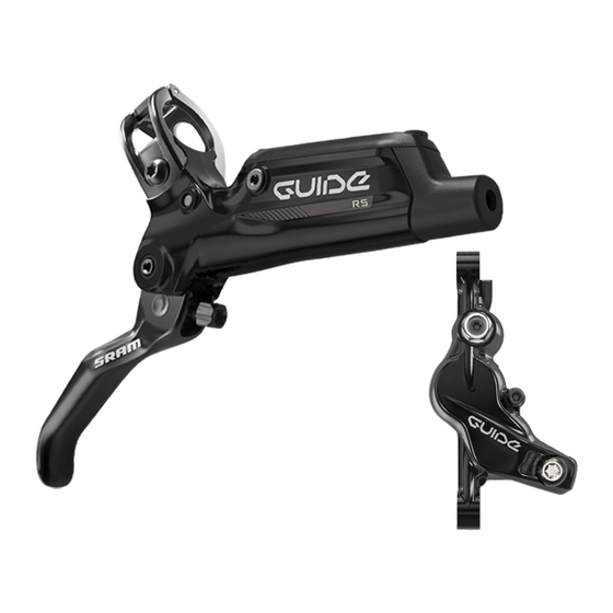
- Page 1 2015 GUIDE DB5, R & RS Service Manual...
- Page 2 LIMITATIONS OF LIABILITY To the extent allowed by local law, except for the obligations specifically set forth in this warranty statement, in no event shall SRAM or its third party suppliers be liable for direct, indirect, special, incidental, or consequential damages.
-
Page 3: Table Of Contents
CALIPER PISTON REMOVAL .......................................... 21 CALIPER PISTON INSTALLATION ....................................... 23 SRAM DB5 CALIPER SERVICE ...............................26 PARTS AND TOOLS NEEDED FOR SERVICE ..................................26 SRAM DB5 CALIPER EXPLODED VIEW ....................................26 TROUBLESHOOTING ............................................27 CALIPER BRAKE PAD REMOVAL ........................................ 28 CALIPER PISTON REMOVAL .........................................29 CALIPER PISTON INSTALLATION ....................................... - Page 4 SAFETY FIRST! We care about YOU. Please, always wear your safety glasses and protective gloves when servicing SRAM products. Protect yourself! Wear your safety gear!
-
Page 5: Brake Service Overview
B r a k e S e r v i c e O v e r v i e w SRAM brake systems need to be serviced periodically to optimize braking function. If brake fluid is leaking from any area of the brake, there may be damage or wear and tear to the internal moving parts. -
Page 6: Lever Service
L e v e r S e r v i c e P a r t s a n d T o o l s N e e d e d f o r S e r v i c e •... - Page 7 G u i d e R L e v e r E x p l o d e d V i e w Reservoir bolt Reservoir cap SwingLink™ Piston assembly SwingLink push rod Bladder Snap ring Binder plug Washer Lever return spring Pinch bolt Hose boot Compression nut...
-
Page 8: Db5 Exploded View
Reservoir cap SwingLink push rod Bladder Piston assembly Snap ring Washer Binder plug Pinch bolt Hose boot Compression nut Washer Lever body Lever return spring Bleed port screws Reach adjuster Pivot pin Lever blade bushings Lever blade SRAM DB5 Exploded View... -
Page 9: Lever Blade Removal
L e v e r B l a d e R e m o v a l N O T I C E DOT fluid will damage painted surfaces. If any fluid comes in contact with a painted surface (i.e. your frame) or printing on the brakes, wipe it off immediately and clean it with isopropyl alcohol or water. - Page 10 Use a T10 TORX® wrench to remove the reservoir cap bolts from the reservoir cap. T10 TORX wrench Remove the reservoir cover and bladder from the lever body. Pour the fluid from the brake lever body into a pan. Separate the bladder from the reservoir cover. Spray isopropyl alcohol on the bladder and the reservoir cover and clean them with a rag.
- Page 11 Use a pick to remove the binder plug. Pick Use a T8 TORX® wrench to remove the pinch bolt. T8 TORX wrench Use the T8 TORX® wrench to push out the pivot pin. T8 TORX wrench 12 13 Remove the lever blade from the lever body. The lever blade has four pieces, the lever blade, the cam/push rod assembly, a washer, and the lever return spring.
- Page 12 P i s t o n A s s e m b l y R e m o v a l Use a pick to remove the lever blade bushings from both sides of the lever. RS only: Use a T8 TORX® wrench to remove the SwingLink™ pivot pinch bolt.
-
Page 13: Piston Assembly Removal
Use long-tipped internal snap ring pliers to apply downward pressure to the lever body and remove the snap ring. Turn the lever body upside down to allow the washer to fall out of the body. Internal snap ring pliers 20 mm or 15 mm Thru Axle Use needle nose pliers to remove the piston assembly. -
Page 14: Piston Assembly Installation
P i s t o n A s s e m b l y I n s t a l l a t i o n N O T I C E DOT fluid will damage painted surfaces. If any fluid comes in contact with a painted surface (i.e. your frame) or printing on the brakes, wipe it off immediately and clean it with isopropyl alcohol or water. -
Page 15: Lever Blade Installation
L e v e r B l a d e I n s t a l l a t i o n RS only: Use needle nose pliers to install the SwingLink™ bushings. If the SwingLink bushings fall out easily, apply a small amount of grease. - Page 16 RS only: Apply a small amount of Loctite® Threadlocker Blue 242® T8 TORX wrench onto the threads of the SwingLink™ pivot pinch bolt. Use a T8 TORX® wrench to thread the SwingLink pivot pinch bolt into the SwingLink. Loctite® Threadlocker Blue 242® 20 mm or 15 mm Thru Axle Lever Blade Installation...
- Page 17 DB5 and R only: Use your hand to insert the lever assembly into the lever body, placing the push rod into the piston and lever return spring on the lever body. Make sure your lever return spring is seated in the lever properly, as seen in the picture.
- Page 18 Line up the cam and lever blade with the holes in the lever body, then press the pivot pin through the holes. Apply a small amount of Loctite® Threadlocker Blue 242® onto the T8 TORX wrench pinch bolt. Use a T8 TORX® wrench to thread the pinch bolt into the lever body.
- Page 19 Press the bladder into the reservoir cap, make sure the bladder is properly seated into the reservoir cap. The bladder should be flush with the cap. Insert the reservoir cap/bladder assembly onto the lever body. Use a torque wrench with a T10 TORX® bit to tighten each reservoir cap bolt to 2.7-3.2 N·m (24-28 in-lb).
- Page 20 Cut the hose to install a new barb and compression fitting. SRAM Hydraulic Hose Cutter Apply DOT grease to the hose barb threads. Thread the hose barb into the hose until it is flush with the end of the hose.
- Page 21 18 14 Apply SRAM® DOT grease onto the compression nut and install the compression fitting and nut into the lever. Use a flare nut crowfoot with a torque wrench to tighten the compression nut to 8 N·m (71 in-lb). Spray isopropyl alcohol on the lever body and clean it with a rag.
-
Page 22: Guide R & Guide Rs Caliper Service
G u i d e R & G u i d e R S C a l i p e r S e r v i c e P a r t s a n d T o o l s N e e d e d f o r S e r v i c e •... -
Page 23: Troubleshooting
T r o u b l e s h o o t i n g 'Sticky' or slow brake pad return feel/excessive lever throw If your brakes feel sticky, and exhibit slow brake pad return and/or excessive brake lever throw, it may be a result of the pistons sticking in the caliper. -
Page 24: Caliper Brake Pad Removal
C a l i p e r B r a k e P a d R e m o v a l Use a 5 mm hex wrench to remove the brake caliper from the fork or frame. Remove the caliper mounting bracket and hardware from the caliper then set the parts aside in the order they were removed. -
Page 25: Caliper Piston Removal
C a l i p e r P i s t o n R e m o v a l N O T I C E DOT fluid will damage painted surfaces. If any fluid comes in contact with a painted surface (i.e. your frame) or printing on the brakes, wipe it off immediately and clean it with isopropyl alcohol or water. - Page 26 Remove the internal caliper o-ring from the outboard caliper half. Place one of the caliper halves, piston side down, on a soft rubber mat or a small section of inner tube on a flat surface. Insert a rubber-tipped blow gun chuck nozzle into the banjo port. C A U T I O N - E Y E H A Z A R D Wear safety glasses.
-
Page 27: Caliper Piston Installation
C a l i p e r P i s t o n I n s t a l l a t i o n N O T I C E DOT fluid will damage painted surfaces. If any fluid comes in contact with a painted surface (i.e. your frame) or printing on the brakes, wipe it off immediately and clean it with isopropyl alcohol or water. - Page 28 Remove the o-rings from the banjo bolt and banjo fitting. Apply a small amount of DOT 5.1 fluid to the new o-rings and install them. Insert the banjo bolt through the outboard caliper half. Apply a small amount of DOT 5.1 fluid to the caliper o-ring and install it onto the banjo bolt.
- Page 29 Servicing your brakes removes all of the fluid from the system. You must bleed the brakes after you service the brake caliper and/or lever. For brake bleed, brake hose shortening, and brake pad replacement instructions, visit www.sram.com/service. Caliper Piston Installation...
-
Page 30: Sram Db5 Caliper Service
S R A M D B 5 C a l i p e r E x p l o d e d V i e w Crimped hose fitting Caliper body bolt Bleed screw Caliper o-ring Piston seal Pad Spreader Caliper hose Caliper port piston Pad pin Piston seal Brake pad Caliper piston E-clip Outboard caliper body Inboard caliper body SRAM DB5 Caliper Service... -
Page 31: Troubleshooting
T r o u b l e s h o o t i n g 'Sticky' or slow brake pad return feel/excessive lever throw If your brakes feel sticky, and exhibit slow brake pad return and/or excessive brake lever throw, it may be a result of the pistons sticking in the caliper. -
Page 32: Caliper Brake Pad Removal
C a l i p e r B r a k e P a d R e m o v a l N O T I C E DOT fluid will damage painted surfaces. If any fluid comes in contact with a painted surface (i.e. your frame) or printing on the brakes, wipe it off immediately and clean it with isopropyl alcohol or water. - Page 33 C a l i p e r P i s t o n R e m o v a l N O T I C E DOT fluid will damage painted surfaces. If any fluid comes in contact with a painted surface (i.e. your frame) or printing on the brakes, wipe it off immediately and clean it with isopropyl alcohol or water.
- Page 34 Place the inboard caliper half, piston side down, on a soft rubber mat or a small section of inner tube on a flat surface. Insert a rubber-tipped blow gun chuck nozzle into the caliper hose port. C A U T I O N - E Y E H A Z A R D Wear safety glasses.
-
Page 35: Caliper Piston Removal
Use a pick to remove the piston seal from inside both the inboard and outboard half of the caliper body and install a new seal inside each caliper body half. N O T I C E Do not scratch the seal gland with a pick. It could result in a slow fluid leak when the brake is applied. -
Page 36: Caliper Piston Installation
C a l i p e r P i s t o n I n s t a l l a t i o n N O T I C E DOT fluid will damage painted surfaces. If any fluid comes in contact with a painted surface (i.e. your frame) or printing on the brakes, wipe it off immediately and clean it with isopropyl alcohol or water. - Page 37 Use a pick to remove the o-ring from the crimped hose fitting. Apply a small amount of DOT 5.1 fluid to the new o-ring and install Align the caliper body halves together. Thread the caliper body bolts into the caliper by hand. Use a torque wrench with a 5 mm hex bit socket to tighten each bolt to 9.8-11.8 N·m (87-104 in-lb).
- Page 38 Servicing your brakes removes all of the fluid from the system. You must bleed the brakes after you service the brake caliper and/or lever. For brake bleed, brake hose shortening, and brake pad replacement instructions, visit www.sram.com/service. crimped hose fitting...
- Page 39 D i s c B r a k e P a d a n d R o t o r B e d - i n P r o c e d u r e All new brake pads and rotors should be put through a wear-in process called 'bed-in'. The bed-in procedure, which should be performed prior to your first ride, ensures the most consistent and powerful braking feel along with the quietest braking in most riding conditions.
-
Page 40: Disc Brake Pad And Rotor Bed-In Procedure
This publication includes trademarks and registered trademarks of the following companies: TORX® is a registered trademark of Acument Intellectual Properties, LLC. Loctite® and Threadlocker Blue 242® are registered trademarks of Henkel Corporation Disc Brake Pad and Rotor Bed-in Procedure... - Page 41 GEN.0000000004801 Rev B © 2017 SRAM, LLC...